|
|
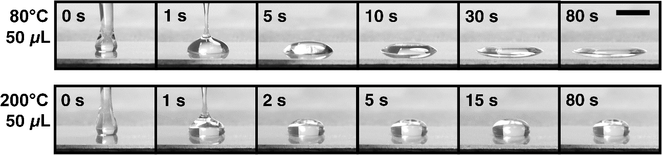
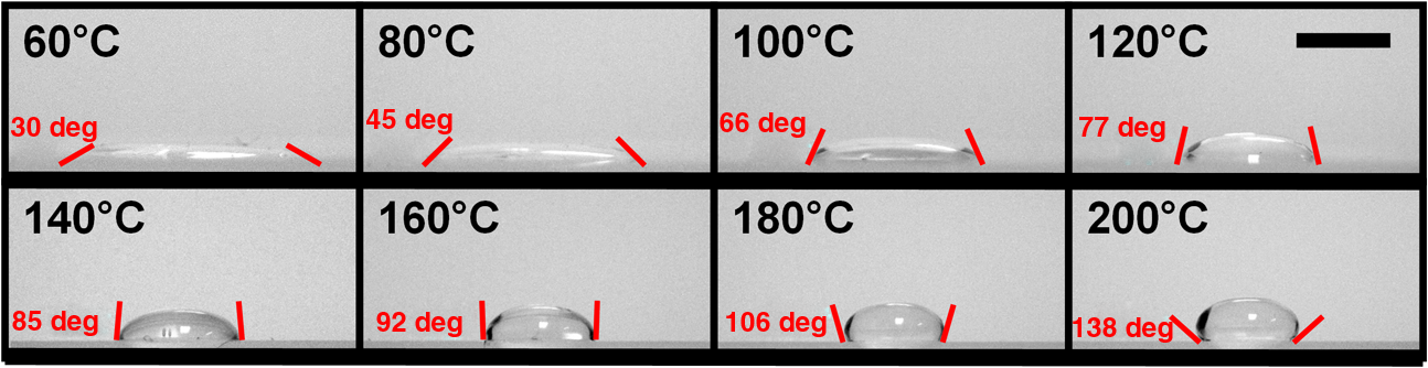
1.IntroductionTraditional lenses are constructed by mechanical polishing or injection molding of rigid materials such as glass or plastics. The high optical quality lens surface requires well-controlled fabrication parameters, which increase complexity and operating costs.1 In contrast, lens formation due to surface energy minimization, such as liquid lenses, has provided an alternative method for creating small lenses of high quality without the requirement of molds or complex parameter control.2 However, freely flowing liquid lenses require a system to provide mechanical stability and prevent evaporation.3 In contrast, lenses can be fabricated by curing liquid polymers to set the lens profile permanently. For example, microlenses with focal lengths on the order of 1 mm have been fabricated by photoresist reflow. Small lenses with millimeter-range focal length are highly applicable to commercial electronics, such as smartphones and digital cameras. Polydimethylsiloxane (PDMS) is optically transparent () in the visible spectrum with a high refractive index () and displays minimal yellowing over time.4 PDMS has been employed to construct microfluidic devices since the 1990s,5 and still maintains its wide applicability to date.6–10 As a lens material, three types of fabrication techniques have been adopted: (1) lithographic methods,11 (2) surface tension driven methods,12 and (3) embossing methods.13 These current approaches demonstrate the feasibility of creating PDMS lenses with good optical characteristics and reproducibility; however, they either require time-consuming fabrication procedures typically measured in hours, or have high costs due to lithographic and molding equipment required, and generally limit the size of the lens to the micrometer scale.12,14 A recently introduced method of creating PDMS lens by gravity-assisted hanging droplet formation has both the advantage of low cost and good optical quality; however, the process requires iterative drop-bake cycles to achieve the desired focal length.15 In this paper, we describe a method to fabricate lenses by inkjet printing of PDMS droplets on a heated surface. The small PDMS droplet is released at a prescribed height from the inkjet print head. Upon impacting the surface, the rather complex interactions of kinetic and surface energy, inertia, gravity, and fluid viscosity cause the droplet to take a plano-convex shape. The printing procedure is robust and can be performed without cleanroom facilities. The rest of the paper is outlined here. In Sec. 2, we describe the rationale behind forming lenses by in situ curing. In Sec. 3, we demonstrate the printing method to fabricate the lenses and discuss characterization results. As an application, we show that our lens can transform a smartphone camera into a microscope by simply attaching the lens without any supporting attachments or mechanism. The strong, yet nonpermanent adhesion between PDMS and glass allows the lens to be easily detached or replaced after use. An imaging resolution of with an optical magnification of has been achieved. 2.ConceptWhen a drop of water is deposited onto a surface, the minimization of interfacial surface energies produces a very smooth and curved surface that can be used as a lens. Likewise, an uncured PDMS droplet can also form a liquid lens. However, the rheological properties of PDMS cause a deposited droplet to flow into a thin pancake shape with little lensing effect. As PDMS is a thermally curable elastomer, the droplet deformation can be intervened by heat accelerated curing in situ. The rapid heating causes the droplet to cure and stop further deformation, thereby preventing excess spreading and retaining significant surface curvature, as shown in Fig. 1(a). By controlling both the volume of the droplet and the preheated surface temperature beneath the droplet, the curing speed can be controlled, which subsequently controls the droplet’s surface curvature and the focal length. The PDMS inkjet print head, as shown in Fig. 1(b), allows us to test these two variables. The PDMS lens can be nonpermanently attached onto a smartphone, as shown in Fig. 1(c), for microscopy applications. Fig. 1Fabrication and application of polydimethylsiloxane (PDMS) lens: (a) changing the temperature of the preheated surface modifies the geometry of a cured PDMS droplet, (b) the PDMS inkjet print head printing droplet lenses on a heated surface, and (c) the lens can be nonpermanently attached onto a smartphone for microscopy applications.  3.Design and ExperimentPDMS solution (Sylgard 184, Dow Corning) was prepared by mixing manufacture recommended proportions of PDMS base and curing agent by a weight ratio of 10:1. After mixing and vacuum bubble removal, an inkjet printing system was set up by incorporating a computer programmable syringe pump with the ability to print with PDMS ink, suspended on a semiautomated stage placed a constant and controlled height above a temperature-controllable hotplate, as shown in Fig. 1(b). 3.1.Temperature-Controlled In Situ PDMS Lens FormationTo prepare a preheated surface, a coverslip was cleaned and placed atop a hotplate. of PDMS was dropped on the coverslip from a 20 mm height with the print head, as demonstrated in Figs. 1(a) and 1(b). PDMS cures at room temperature, but exhibits accelerated curing with increasing temperatures. The procedure was repeated with temperature increments of 20°C, from 60 up to 200°C. At lower temperatures, PDMS droplets require a longer time to cure (roughly 350 s at 60°C), allowing the viscous liquid to spread across the surface as gravity pulls the liquid toward the surface. The viscosity of the uncured PDMS increases as the curing process starts, and an equilibrium is attained when the viscous forces balance out the gravitational force. This forms a very thin, flat lens with negligible curvature and little optical power. In contrast, heat-accelerated curing solidifies the liquid droplet in situ, in effect stopping the spreading process. This limits the droplet to spread into a smaller diameter and at the same time, retains significant surface curvature effective for refractive ray bending. Figure 2 shows the morphological evolution of droplets during in situ curing at 80 and 200°C. At 80°C, it can be seen that the initial droplet spread is wider and continues to flow out into a thin shape before curing completes at after dispensing. At 200°C, the PDMS droplet virtually cures on contact, causing significant curvature. No burning or charring was observed at these temperatures. Side views of droplets cured at 60 to 200°C are shown in Fig. 3 for comparison. It is seen that as the surface temperature increases, the time required for droplet curing decreases, the flow of the droplet is limited, and the subsequent droplet exhibits a decreased diameter, increased height, and increased surface contact angle, thus forming a smaller radius of curvature which leads to a higher optical power. 3.2.Volume-Controlled In Situ PDMS Lens FormationTo investigate the relationship between focal length and droplet volume, the hotplate was set to a constant temperature of 200°C and different volumes of PDMS were deposited on the surface while all other conditions remained identical. Volumes of 10 to were used, respectively, with the resulting side views and geometrical measurements shown in Fig. 4. As the droplet volume increases, the lens diameter increases intuitively; however, the contact angle only varies within . The center portion of the lens is found to exhibit decreasing curvature and eventually flattens for increasing volume. This limitation makes it difficult to create high-magnification lenses in diameter using this method. Fig. 4Side view of PDMS droplets (various volumes) deposited onto a surface at 200°C temperature. Scale bar is 5 mm.  The properties of the lens are determined by its geometric parameters. Since the curing temperature of PDMS determines the speed of polymerization, and thus the contact angle and diameter of the lens droplet, the focal length of the lens can be accurately tuned in a single step. Similar to other liquid lenses, the droplet experiences uniform surface forces from all sides during curing, which greatly eliminates surface roughness. 3.3.Printing RepeatabilityTo demonstrate the repeatability of the inkjet printing technique in fabricating lenses, 20 lenses were made for each volume of 10, 25, 50, 75, and , at each temperature between 100 and 200°C. Due to limited hotplate area, only five lenses were made for the volumes due to their larger size. Figure 5 shows the trend of the lens diameter with respect to the lens volume and curing temperature. It is observed that for volumes , the diameter deviated in all cases, but was generally controlled within 2.7% in most cases. 3.4.Optical Characterization of Lenses Cured at 200°CFrom the preceding sections, it is shown that at a certain fixed hotplate temperature, decreasing the droplet volume creates a smaller droplet with a smaller radius of curvature, or a shorter focal length. As the PDMS lenses cured at 200°C have the smallest diameter, we next characterized the focal lengths of the sequence of different volume lenses cured at 200°C. The setup to characterize the focal length is shown in Fig. 6(a). The output from a fiber-coupled diode laser (Newport Model 505 laser diode driver connected to fiber pigtailed laser diode LD-635-31A) was passed through a convex lens (L1) (Thorlabs LA1131-ML) with a focal length of 50 mm, a neutral density filter (ND) (Thorlabs ND10A), an iris (I) (Thorlabs ID25/M), and a glass slide (G) on which the PDMS lens (L2) was attached. A CCD camera (Amscope MT 300, Amscope) with a pixel size of was affixed on a micrometer stage with a travel range of from the PDMS lens. The error with the stage measurement was . For PDMS lenses with a focal length , the micrometer stage was removed. the CCD camera was positioned manually with a ruler and the associated error was . Fig. 6Determining the focal length of the PDMS lenses. (a) Schematic of optical path; optical path of diverging diode laser enters a convex lens with 40 mm focal length (L1), a neutral density filter (ND), a glass slide (G) for support, and the PDMS lens (L2); the focused beam is captured by the CCD camera. (b) CCD camera image showing beam intensity profile when tested with the , 200°C lens, at distance of 6.0, 6.3, and 6.6 mm, respectively. (c) The trend of focal length with different lens volumes from 10 to .  Figure 6(b) shows the laser beam spot captured on the CCD camera with the lens. The image has been transformed into gray scale before intensity analysis with MATLAB® (Mathworks). The beam intensity profiles along the vertical and horizontal directions are also shown. The images were captured at 5.4, 5.6, and 5.8 mm distances. The focal length is found to be 5.6 mm, where the full-width half-maximum of the point spread function is captured as the minimum with the CCD camera. Figure 6(c) shows the comparison of the focal length of lenses created with various droplet volumes at 200°C. The focal lengths for volumes of 10, 25, 50, 75, 100, 125, 150, 175, and were , , , , , , , , and , respectively. The optical power of a convex lens is the degree to which it converges light and can be expressed by the equation , where is the power of the lens and is the focal length. The numerical aperture of a lens is commonly expressed as , where is the index of refraction of the medium in which the lens is working () and is the half-angle of the maximum cone of light that can enter or exit the lens. For the PDMS lens with a focal length of 5.6 mm ( cured at 200°C), the optical power was found to be . The lens has a usable radius of 1.02 mm, and the half-angle is found to be 10.32 deg, leading to an NA of . Future work is needed to fully characterize the lens surface curvature for a more accurate NA estimate. 3.5.Minimum Resolvable Feature SizeAdd-on accessories to turn a smartphone into a microscopic imaging device are widely available; however, most of these attachments are bulky or require device-specific attachment components.16 To demonstrate a practical application, the PDMS lens ( cured at 200°C) was attached to a Nokia Lumia 520 budget smartphone camera (Microsoft, Richmond, Virginia) as shown in Fig. 1(c). The camera has a 5-megapixel sensor and the minimum focus distance of the smartphone camera is 10 cm as specified by the manufacturer. The adhesive property of PDMS on glass and plastic surfaces allowed the PDMS lens to be attached nonpermanently onto the camera window without additional support and was able to be used in our experiments for at least 30 min at a time without falling off. The effective focusing distance of the smartphone with the PDMS lens was . In order to determine the minimum resolvable feature size of the smartphone-PDMS lens system, a binary spoke target with a minimum feature size of was imaged. The spoke target was manufactured commercially using electron beam lithography with chrome on glass, as shown in Fig. 7. The central portion of the target was imaged with an Olympus IX-70 (Olympus Corp) microscope with magnification, as shown in Fig. 7(a). The image obtained by the smartphone-PDMS lens system with a separate backlight source is shown in Fig. 7(b). The width of the 64 spokes decrease linearly from from the outer rim to at the inner rim. Intensity profiles of the images were obtained using MATLAB®. Fig. 7Determining minimum resolvable feature size by imaging a minium line width binary spoke target: (a) obtained with microscope and (b) obtained with a smartphone with a , 200°C PDMS lens. The three line sections, respectively, indicate the region where the spoke widths are 5, 3, and . V, fringe visibility.  A perfect reproduction of the spoke target pattern would yield an intensity represented by a square wave with 64 cycles, each with the highest intensity at 256 bits and the lowest intensity of 0 bits. Fringe visibility () quantifies the contrast of interference of the optical system and is defined as . An ideal output yields a visibility of 1, while a featureless output yields a visibility of 0. For a 256 bit mask function, where bit and bit, . The respective maximum and minimum intensities and fringe visibility obtained for different spoke line widths from the microscope and smartphone-PDMS lens system are summarized in Table 1. Table 1Intensity and fringe visibility of spoke target image.
The visibility of the pattern from the smartphone-PDMS lens system is lower than that of the microscope; however, the intensity map indicates that 62 of 64 patterns can be resolved. It is important to note that the imaging contrast highly depends on the camera hardware, and internal processing performed by the smartphone may have an important role in determining the minimum resolution of the system. A higher-end smartphone camera may yield better results than those obtained for this analysis. A further resolution test was performed using a standard USAF 1951 resolution test target (#58-198 Edmund Optics Inc.), in order to prevent radially symmetric distortions from affecting the previous method of resolution determination. The target was separately imaged using a microscope with magnification, as shown in Fig. 8(a), and the smartphone-PDMS lens system with a separate backlight source, as shown in Fig. 8(b). The USAF patterns selected are, respectively, from group 8 element 6 vertical and horizontal (top), and group 8 element 5 vertical and horizontal (bottom), yielding a respective line width of 1.10 and . The dotted lines indicate the region of the pattern from where the light intensity was obtained. Fig. 8Determining minimum resolvable feature size by imaging a USAF 1951 resolution test target with line widths of (top patterns) and (bottom patterns): (a) obtained with microscope and (b) obtained with a smartphone with a , 200°C PDMS lens.  Fringe visibility was calculated for each pattern and summarized in Table 2. It is seen that the visibility of the 1.23 and test patterns from the smartphone-PDMS lens system remains lower than that of the microscope; however, the intensity map clearly displays the three peak patterns. The minimum resolvable feature and fringe visibility is comparable to that performed using the binary spoke target. Table 2Intensity and fringe visibility of USAF 1951 resolution test target image.
3.6.Smartphone Microscopy ApplicationFigure 9 demonstrates the potential of the smartphone-PDMS lens system to be used in biological and biomedical research. A cross-section of a human skin-hair follicle histological slide (AmScope) was employed, and the image captured by an Olympus IX-70 microscope was compared with that by the smartphone-PDMS lens system. Figures 9(a), 9(b), and 9(c) show the sample imaged under the microscope at , , and , respectively, while Fig. 9(d) shows the same sample imaged with the smartphone-PDMS lens system. A magnified inset of each image is shown in Figs. 9(e) to 9(h). It can be seen that with the smartphone-PDMS lens system, individual skin cells can be observed. Fig. 9Comparison of human skin and hair follicle cross-section histology slide. (a), (b), (c), and (d) are, respectively, imaged with an Olympus IX-70 microscope at magnification, magnification, magnification, and with a Nokia Lumia 520 smartphone with PDMS lens system. (d), (e), (f), and (g) show the magnified regions, respectively.  The base magnification of the lens was found to be by comparing the observed size of an arbitrary structure in a clearly focused image taken with the smartphone and the aforementioned microscope. The magnification of the smartphone with PDMS lens can be further enhanced by combining software based digital magnification. 4.ConclusionIn this paper, we describe an inkjet printing technique to fabricate optical lenses by in situ curing PDMS droplets of controlled volume and at controlled temperature. This single-step method allows lenses with different focal lengths to be made by varying the droplet volume and surface temperature. The semiautomated printing technique is highly scalable for lenses of different focal lengths and can be modified for parallel fabrication with higher throughput. The material cost of the PDMS was calculated to be USD for a lens and can be conveniently attached to a smartphone camera via the strong but nonpermanent adhesion between PDMS and glass. An imaging resolution of and an optical magnification of have been demonstrated with a PDMS lens of 5.6 mm focal length attached to a low-cost smartphone. We believe that the simplicity and robustness of this printing process will introduce a new standard for fabricating lenses with various focal lengths without the requirement of large manufacturing facilities. Future work will include fabrication and characterization of smaller lenses that will yield greater magnification but have been difficult to manipulate due to their small sizes. AcknowledgmentsWei-Chuan Shih acknowledges the National Science Foundation (NSF) CAREER Award (CBET-1151154), National Aeronautics and Space Administration (NASA) Early Career Faculty Grant (NNX12AQ44G), and a grant from Gulf of Mexico Research Initiative (GoMRI-030). ReferencesP. J. Gramann and T. A. Osswald, Injection Molding Handbook, Hanser Gardner Publication Inc, Cincinnati
(2002). Google Scholar
F. A. Chowdhury and K. J. Chau,
“Variable focus microscopy using a suspended water droplet,”
J. Opt., 14 055501
(2012). http://dx.doi.org/10.1088/2040-8978/14/5/055501 JOOPDB 0150-536X Google Scholar
H. H. Myint et al.,
“Water droplet lens microscope and microphotographs,”
Phys. Educ., 36
(2), 97
–101
(2001). http://dx.doi.org/10.1088/0031-9120/36/2/301 PHEDA7 0031-9120 Google Scholar
J. L. Wilbur et al.,
“Elastomeric optics,”
Chem. Mater., 8
(7), 1380
–1385
(1996). http://dx.doi.org/10.1021/cm950579d CMATEX 0897-4756 Google Scholar
E. Kim, Y. Xia and G. M. Whitesides,
“Polymer microstructures formed by moulding in capillaries,”
Nature, 376
(6541), 581
–584
(1995). http://dx.doi.org/10.1038/376581a0 NATUAS 0028-0836 Google Scholar
S. C. Lin et al.,
“A low sample volume particle separation device with electrokinetic pumping based on circular travelling-wave electroosmosis,”
Lab Chip, 13
(15), 3082
–3089
(2013). http://dx.doi.org/10.1039/c3lc50343g LCAHAM 1473-0197 Google Scholar
M. Li et al.,
“Stamping surface-enhanced Raman spectroscopy for label-free, multiplexed, molecular sensing and imaging,”
J. Biomed. Opt., 19
(5), 050501
(2014). http://dx.doi.org/10.1117/1.JBO.19.5.050501 JBOPFO 1083-3668 Google Scholar
J. Shi et al.,
“Focusing microparticles in a microfluidic channel with standing surface acoustic waves (SSAW),”
Lab Chip, 8
(2), 221
–223
(2008). http://dx.doi.org/10.1039/B716321E LCAHAM 1473-0197 Google Scholar
M. Li et al.,
“Reagent- and separation-free measurements of urine creatinine concentration by stamping surface-enhanced Raman scattering (S-SERS),”
Biomed. Opt. Express, 6
(3), 849
–858
(2015). http://dx.doi.org/10.1364/BOE.6.000849 Google Scholar
M. Li et al.,
“Microfluidic surface-enhanced Raman scattering (SERS) sensor with monolithically integrated nanoporous gold disk (NPGD) arrays for rapid and label-free biomolecular detection,”
J Biomed. Opt., 19
(11), 111611
(2014). http://dx.doi.org/10.1117/1.JBO.19.11.111611 Google Scholar
M. H. Wu, C. Park and G. M. Whitesides,
“Fabrication of arrays of microlenses with controlled profiles using gray-scale microlens projection photolithography,”
Langmuir, 18
(24), 9312
–9318
(2002). http://dx.doi.org/10.1021/la015735b LANGD5 0743-7463 Google Scholar
E. Bonaccurso et al.,
“Fabrication of microvessels and microlenses from polymers by solvent droplets,”
Appl. Phys. Lett., 86 124101
(2005). http://dx.doi.org/10.1063/1.1886263 APPLAB 0003-6951 Google Scholar
H. Yabu and M. Shimomura,
“Simple fabrication of micro lens arrays,”
Langmuir, 21
(5), 1709
–1711
(2005). http://dx.doi.org/10.1021/la046996z LANGD5 0743-7463 Google Scholar
S. Y. Lee et al.,
“Thermal actuated solid tunable lens,”
IEEE Photonics Technol. Lett., 18
(21), 2191
–2193
(2006). http://dx.doi.org/10.1109/LPT.2006.883891 IPTLEL 1041-1135 Google Scholar
W. M. Lee et al.,
“Fabricating low cost and high performance elastomer lenses using hanging droplets,”
Biomed. Opt. Express, 5
(5), 1626
–1635
(2014). http://dx.doi.org/10.1364/BOE.5.001626 BOEICL 2156-7085 Google Scholar
H. Y. Zhu et al.,
“Optical imaging techniques for point-of-care diagnostics,”
Lab Chip, 13
(1), 51
–67
(2013). http://dx.doi.org/10.1039/C2LC40864C LCAHAM 1473-0197 Google Scholar
BiographyWei-Chuan Shih is an assistant professor of electrical & computer engineering, biomedical engineering, and chemistry at University of Houston. He received his PhD degree from the Massachusetts Institute of Technology under professor Michael S Feld. He is a recipient of NSF CAREER Award and NASA inaugural Early Career Faculty Award. His research interests are in biophotonics, nano-plasmonics, multi-modal neural stimulation and sensing, point-of-care technology, cancer theranostics, environmental sensing, hyperspectral microscopy and imaging, N/MEMS, and laser-based 3D manufacturing. He has published more than 50 articles and is the inventor of 6 issued patents. |
||||||||||||||||||||||||||||||||||||||||||||||||||||||||||||||||||||||||||||||||