|
|
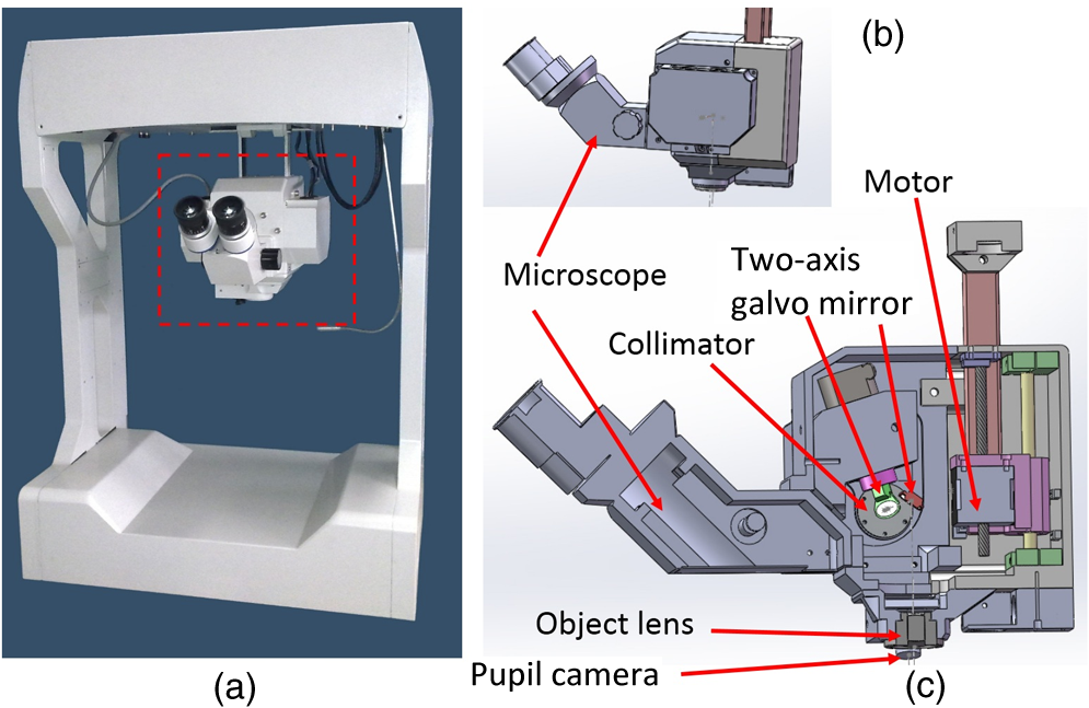
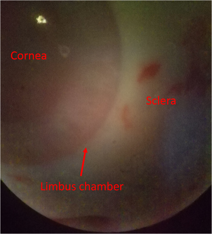
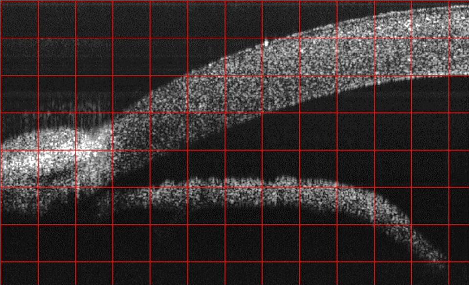
1.IntroductionGlaucoma remains the second leading cause of blindness worldwide, and its prevalence increases with age.1,2 In pathophysiology, glaucoma is related to elevation of intraocular pressure (IOP).3,4 Ever since the first glaucoma surgery took place in 1856, the goal has been to decrease IOP. This goal has been met by surgical manipulation of the aqueous inflow or outflow pathways.5 Aqueous outflow can be increased by creating a new outflow pathway by a filter implant, such as the Ahmed valve (New World Medical, Inc., Rancho Cucamonga, Massachusetts). The device works by bypassing the trabecular meshwork (TM) and redirecting the outflow of aqueous humor through the drainage tube.6 In the filter implant, the drainage tube was inserted into the anterior chamber approximately 2 to 3 mm away from a paracentesis with a sharp needle below the limbus chamber.7,8 Another way is to selectively remove TM and the inner wall of the Schlemm’s canal (SC) to increase the physiologic aqueous outflow, such as the Trabectome™ (Neomedix Corp., Tustin, California) surgery.9–11 In Trabectome surgery, the tip of the Trabectome was inserted into the anterior chamber, and the strainer-like tissue (TM) was removed using an electrosurgical pulse.8,12,13 Both the implantation method and the Trabectome method are subject to problems involving visualization and positioning during the surgical maneuvers. The position of the paracentesis in the filter implant and the position of the scleral incision in the Trabectome should be determined.6,7,12,14 The needle should be inserted parallel to the iris in a filter implant to prevent it from coming into contact with the cornea or iris and to minimize the rate of postoperative complications.7 The tip of the Trabectome should be inserted into SC through TM.8,10 These steps need direct visualization and precise positioning. The goniolens can provide direct visualization, but it cannot provide precise axial position information.15,16 Scanning electron microscopy and confocal laser scanning microscopy have been used in glaucoma surgery.17 These methods cannot provide tomographic images of the anterior segment during surgery. Ultrasound biomicroscopy has also been used to image the surgical results,17 however, it needs to come into contact with the eye to work, which makes it difficult to guide the surgery. Optical coherence tomography (OCT) enabling noncontact, high-resolution, cross-sectional views of the anterior and posterior segments of the eye has demonstrated strong clinical success in ophthalmological imaging.18,19 The TM and SC can be imaged using high-resolution OCT.20–23 Furthermore, OCT is more suitable for applications involving microsurgical guidance than MRI, CT, ultrasound, and other methods due to its noncontact and tomography capability.15,16,24,25 Zhang et al. have described a real-time intraoperative four-dimensional Fourier Domain OCT (FD-OCT) for microsurgical guidance, but it did not integrate with a microscope, which limits its usefulness.25 Binder et al. have reported a Carl Zeiss Meditech Cirrus HD-OCTTM system that adapted the optical pathway of a Zeiss OPMI VISU 200 surgical microscope.26 A microscope-mounted, commercially available spectral-domain OCT camera (iOCT, OptoMedical Technologies GmbH, Luebeck, Germany) was used to optimize descement membrane endothelial keratoplasty.27 The iOCT device was connected to the camera port of an OCT-compatible microscope (Hi-R 900 A NIR; Moeller-Wedel, Wedel, Germany). Tao et al. have reported in vivo human retinal imaging using an intraoperative microscope-mounted OCT system and an intraoperative OCT with electrically tunable focus and heads-up display.28–30 Their system involved an 840-nm super luminescent diode, which may not be as suitable as longer wavelengths, and these systems cannot provide real-time three-dimensional monitoring because their volumetric rendering must be postprocessed.26–28,30 In this paper, a microscope-integrated OCT with a 1310-nm swept source was developed. The 1310-nm light source was found capable of facilitating deeper penetration and increasing the system signal-to-noise ratio (SNR) in the anterior segment application.20,22 The mechanical design was found to be suitable for the human ophthalmology eye surgery in vivo using three axis motors as rough regulators. A two-graphic processing unit (GPU) architecture was used to increase the processing speed and enable real-time volumetric rendering, enabling real-time monitoring of the anterior segment surgery. A grid was inserted into the scanning image or volumetric image to help to determine the position of the target. Finally, filter implants and Trabectome surgery were simulated to highlight the effectiveness of this integrated system. 2.Methods2.1.System SetupA custom-built OCT system was integrated with a custom-built microscope to guide the glaucoma surgery. Figure 1 shows the setup of the microscope-integrated SS-OCT. The swept source was centered at 1310 nm (HSL-2100-HW, Santec, Japan), with a wavelength scan range of , a coherence length of 6 mm, and a scanning speed of 50 kHz. A Michelson interferometer (INT-MSI-1300B, Thorlabs) with a balance detector was used to detect the interference signal. A laser diode with a 660-nm wavelength function served as an aiming laser. Two fiber polarization controllers were applied in the sample arm and the reference arm to control the polarization. A Mach-Zehnder interferometer (INT-MZI-1300B, Thorlabs) with free spectral range was used to convert the spectral fringe in the wavelength domain to the wavenumber domain. The interference signal of the Michelson interferometer (MSI) and the Mach-Zehnder interferometer (MZI) were acquired and transferred to the computer using a dual-channel acquisition card (PCIe-1422, Gage) at the rate of 200 million samples (MS) per second. The two-axis galvo driver was controlled, and the B-scan was synchronized with frame acquisition on the data acquisition card by a waveform generation card (PCI-6731, NI). A scan lens with a 120-mm focus length was used after the galvo mirrors. After calibration, the actual axial resolution was in air, corresponding to in tissue. The ophthalmology microscope was integrated with the OCT system. Fig. 1Optical schematic of the microscope integrated swept-source optical coherence tomography (SS-OCT) system. ND, neutral density filter; CL, collimator; PC, polarization controller; EP, eyepiece; MG, magnification; OL, object lens; GM, galvo mirrors.  A custom-built ophthalmology microscope based on a commercial ophthalmology microscope (ASOM-3, Corder, China) was adapted in this system. It contains an object lens with a 125-mm focus length, a magnifier, and two eyepieces with 20 mm focus lengths. Each eyepiece’s interpupillary distance adjustment scope ranged from 55 to 75 mm and diopter adjustment range ranged from to Diopter. The magnification was divided in , , and , resulting in the total magnification divided in , , and . An adjustable halogen lamp with a fiber connector was used to illuminate the field of view (FOV) of the microscope. The maximum illumination was 60,000 lux and the spot radius was 50 mm, which were within the maximum permissible exposure limits. The focus length of the microscope was different from the scanning focus length of the SS-OCT system, so the placement of the microscope must be adjusted carefully to make sure that they image the same focus plane. The position of the patient’s eye is crucial to the successful completion of glaucoma surgery. The surgical team or apparatus must rotate the patient’s head, adjust the head’s distance from the doctor, and perform similar actions. A custom-built mechanical system was developed in this study to produce an adjustable system. Figure 2 shows the mechanical design which is based on previous work.20 The gantry structure allows the patient to lie down, enables the patient to be more comfortable, and stabilizes the patient’s eye. This structure also provides space for the surgery. Here, two-dimensional electric translation motors ware placed in the gantry structure. An integrated box contains the sample arm of the OCT system, and the ophthalmology microscope was connected to this two-dimensional motor as shown in Fig. 2(a). This box can be moved forward, backward, right, and left using motors to extend the image range of the microscope and OCT. The MSI, MZI, reference arm, and the galvanometer driver board were fitted to the gantry structure in the manner that made the most efficient use of space. Figure 2(c) shows the profile of the integrated box. The sample arm of the OCT system contained a fiber collimator, a two-axis galvo mirror and a scan lens. These were assembled in the box. A microscope and a pupil camera were placed outside of the box. A -direction motor was placed in the integrated box, making it possible to adjust the focus plane of the OCT scanning and the microscope imaging. Using the three-axis motors, the image range of the microscope and SS-OCT can be enlarged to satisfy the requirements of the surgery. All of the motors are controlled by a foot pedal, which leaves the observer’s hands free to handle the surgery. 2.2.Data ProcessingBecause the surgical instrument must be inserted into the eye, the real-time imaging and real-time positioning of the surgical instrument is crucial to glaucoma surgery. The cornea, iris, sclera, and the limbus cornea should be imaged, and their relationship with the surgical instrument can be measured during the surgical procedure. Another key function for the glaucoma surgery is volumetric rendering. The tube should be laid across the cornea and cut with sharp scissors to create a beveled edge with the opening toward the cornea. During the filter implant surgery, it is extended 2.5 to 3 mm into the anterior chamber.7,8,14 All these procedures require three-dimensional imaging. In order to satisfy these requirements, a signal processing system based on two-GPU architecture was developed. A personal computer containing an Intel quad-core central processing unit and two GPUs hosted the data acquisition card. The data acquisition card was plugged into a PCI Express X4 slot whose transfer rate can reach million bytes per second, enabling real-time data transfer. The sampling rate of the data acquisition was set to 200 MS, resulting in the acquisition of pixels in every swept period of the light source. The data were processed by performing resampling, background subtraction, fast Fourier transforms (FFT), and image creation in the first GPU, which was here called Tesla K20M. This contained 2496 processors. In order to enhance the SNR and the axial resolution, the time-domain interpolation with the 31 cut-off length window was applied in the resampling step.31,32 In order to fit the axial range, pixels were resampled for the acquired data by the time-domain interpolation.31 The overall processing speed was found to reach A-lines per second,32 which is much faster than the frequency of the light source, resulting in real-time processing capability for this OCT system if a faster swept source is used. Another GPU (NVIDIA GeForce GTX 650Ti) with 1024 processors was used for the volumetric rendering to satisfy the real-time OCT display. A volume rendering by ray-casting has been developed to produce a better presentation of the procedure of the surgery. The ray-casting algorithm was run in the GPU to provide the heavy computing duty.16,33 About 60 frames per second can be rendered by the GTX 650Ti when the simulated volume data were set to in pixels. Thus, the volumetric rendering can be updated at every scanning frame in the data processing, providing a better visualization during the surgery maneuvers. The region of interest can be set to determine the balance between the rendering speed and the imaging area. The software was developed under Microsoft Visual Studio 2008, and the GPU was programmed by the NVIDIA’s compute unified device architecture, application programming interfaces. To enable precise positioning, a grid was added to the image during scanning if needed. This grid size can be adjusted for use. In the three-dimensional scanning, the number of the frame was calculated to accomplish the grid size. A two-dimensional grid is inserted every frame to produce a three-dimensional grid. The surgical instruments and their spatial relationship with the anterior segment’s structure can be measured with the help of this grid. 3.Results and DiscussionAt the beginning of the test, the scan head was moved and the focus was adjusted to the interested area using three-axis motors. After this rough adjustment, a clear image was produced by the microscope. Figure 4 shows the eye image in the microscope. The study was conducted in accordance with the tenets of the Declaration of Helsinki. The ethics committee of the Peking University Third Hospital approved the study. The paracentesis needle in the filter implant and the Trabectome surgery was injected into anterior chamber below the limbus.7,12,14 OCT can image the limbus to help to distinguish the cornea from sclera. Figure 5 shows the imaging result of a rabbit’s anterior segment. The image range was . The grid size was set to 0.5 mm in both the direction and axial direction. The position of the sclera, cornea, and limbus cornea can be determined using the grid. This image guides positioning of the microscope; therefore, clinical decisions can be made more precisely during ophthalmic surgery. A filter implant experiment was performed to evaluate the system’s performance. The implant surgery contains fornix-based incision, valve insertion, tube trim, paracentesis, tube insertion, tube coverage, and suture steps.7 In order to stimulate the harsh environment in surgery, a frozen rabbit’s eye with corneal edema was adopted in this experiment. As the position was chosen, a needle was used to create a track through a rabbit’s eye, and an Ahmed valve was injected into the eye around the limbus cornea. During the injection, the valve was observed using the microscope and OCT system. Using image aid positioning, the surgical handler can monitor the instrument’s status during the surgical procedure. The angle and the position of the tube’s tip can be controlled during insertion into the eye. With real-time monitoring, the tip was inserted parallel to the iris, which prevented it from coming into contact with the cornea or iris, thus reducing the risk of infection. When the injection was almost done, a three-dimensional scan was produced to evaluate the position of the valve. Figure 6(a) shows one of the B-scan images. Figure 6(b) shows the image of the Ahmed valve. Because the tube of the valve was made of medical grade silicone and because of the angle of the scan,7 only the outer wall, inner wall, and tip of the tube could be imaged. An incision injury by the paracentesis was also imaged. Figures 6(c)–6(d) show volumetric imaging of the injected valve in different views. The region of interest (ROI) of the imaging process was . The position can be evaluated by these walls. A three-dimensional grid was inserted into the volumetric data. The position of the tip was measured using this grid. In this insertion, the tip of the valve was placed more than 3 mm away from the chamber angle and below the cornea. The beveled edge of the tip was opened toward the cornea. The tube should be extended to 3 mm into the anterior chamber to minimize the risk of the tube-cornea touching the anterior chamber.7,8 This made it possible to pull the tube out a little in this simulation. As shown in the Fig. 6(d), the cut edge of paracentesis can be imaged using volumetric rendering, which would be helpful for stabilizing the tube and making sure that the tube not be tight because the tube should be secured to the sclera. All the results listed above indicate that the entire surgical procedure can be monitored using this system. Fig. 6The volume rendering of the injector by SS-OCT: (a) B-scan image of the inserted tube, (b) Ahmed valve model S2, (c) volumetric render of the inserted tube (Video 1), and (d) cutting edge of the paracentesis. (Video 1, MPEG, 0.7 MB) [URL: http://dx.doi.org/10.1117/1.JBO.20.7.076001.1].  A Trabectome surgery was also simulated. The goal of Trabectome surgery is to remove the TM tissue using an electrosurgical pulse.9 The surgical procedure contains sclera incision, visco-elastic, goniolens placement, ablation, rotate tip, ablation, irrigate and aspirate, and suture steps.12 The tip of the footplate was inserted through the TM into SC. The relative position of the tip and the TM is important to successful Trabectome surgery.9,12,34 Volumetric rendering can provide direct visualization of the tip and the TM. Figure 7(a) shows the tip of the Trabectome. This tip was inserted into the eye of a rabbit and three-dimensional scanning was performed. Figures 7(b) and 7(c) show the rendering results. The ROI of imaging was set to . As the images show, the insulated footplate and the active electrode of the Trabectome were visible during volumetric imaging. This provided precise positioning for clinical decisions during the surgical procedure. Fig. 7Trabectome surgical results: (a) trabectome tip, (b) volumetric rendering of the trabectome tip (Video 2), and (c) another view of the rendering. (Video 2, MPEG, 0.7 MB) [URL: http://dx.doi.org/10.1117/1.JBO.20.7.076001.2].  As shown in the rendering results described above, the microscope-integrated OCT system can be used to distinguish the cornea from the sclera and measure the position of the tube in the filter implant and the tip of the Trabectome surgery. The microscope-integrated OCT system can facilitate both implantation of the filter and the Trabectome surgery. Clinical decisions, such as position and length of injection, and the specific tissue to be removed and the specific type of Trabectome surgery, tend to be made by doctors based on experience. There is no standard, objective assessment procedure to follow. This system can provide a high-resolution image of the surgical instrument the structure of the tissue. It aids in the objective assessment of their relative positions during glaucoma surgery. 4.ConclusionsThis paper demonstrated the use of an image-aided positioning system in in vivo glaucoma surgery. The position of the surgical instrument needed to be monitored during the surgical procedure. In order to meet the requirements of the glaucoma surgery, a microscope was integrated to an SS-OCT system. This SS-OCT system used a 1310-nm light source to produce a better image of the anterior segment. The position of the microscope was carefully adjusted to produce images within the same FOV. The integrated head was placed in a three-axis motor system with a very large screw tuning range to make it easy to adjust during surgery. A real-time, high-speed signal processing and ray-casting rendering based on two-GPU architecture was developed to provide real-time imaging guidance for anterior surgery. A grid was inserted into the image or volumetric rendering to help assess the relationship between the surgical instruments and the anterior segment’s structures. Two experiments were performed to confirm this integrated system’s capability. The results of these two experiments show that the surgical instruments can be imaged to reveal their relative spatial positions to the anterior segments’ structures. This helps in making more precise clinical decisions. The microscope-integrated SS-OCT system can provide a technique for clinicians to objectively assess the procedure of glaucoma surgery, and this reduces the subjective decisions based solely on experience. Additional work is required for further integration of this system. Volume feature identification or matching should be developed to provide feedback regarding the position of the surgical instruments and the distance between the target tissue and the surgical instruments in real time. This function may provide guidance for a raster scanning protocol in angle search or real-time imaging. A faster scanning rate is needed to facilitate a faster volumetric rendering, which is limited by the swept speed of the swept light source. AcknowledgmentsWe acknowledge the support from Outstanding Young Scientists, Chinese Academy of Sciences, the union project of Peking University Third Hospital and Chinese Academy of Sciences (Grant Nos. 74490-04 and KJZD-EW-TZ-L03-5), the National Major Scientific Equipment Program (Grant No. 2012YQ120080), the National Science Foundation of China (Grant No. 61108082), the National Hi-tech Support Project for the Twelfth Five Years’ Blueprint (Grant No. 2012BAI08B04), and the West Light Foundation of the Chinese Academy of Sciences. ReferencesR. N. Weinreb and P. T. Khaw,
“Primary open-angle glaucoma,”
Lancet, 363
(9422), 1711
–1720
(2004). http://dx.doi.org/10.1016/S0140-6736(04)16257-0 LANCAO 0140-6736 Google Scholar
H. A. Quigley,
“Number of people with glaucoma worldwide,”
Br. J. Ophthalmol., 80
(5), 389
–393
(1996). http://dx.doi.org/10.1136/bjo.80.5.389 BJOPAL 0007-1161 Google Scholar
A. Sommer et al,
“Relationship between intraocular pressure and primary open angle glaucoma among white and black Americans. The Baltimore Eye Survey,”
Arch. Ophthalmol., 109
(8), 1090
–1095
(1991). http://dx.doi.org/10.1001/archopht.1991.01080080050026 AROPAW 0003-9950 Google Scholar
R. D. Ten Hulzen and D. H. Johnson,
“Effect of fixation pressure on juxtacanalicular tissue and Schlemm’s canal,”
Invest. Ophthalmol. Vis. Sci., 37
(1), 114
–124
(1996). IOVSDA 0146-0404 Google Scholar
A. L. Coleman,
“Advances in glaucoma treatment and management: surgery,”
Invest. Ophthalmol. Vis. Sci., 53
(5), 2491
–2494
(2012). http://dx.doi.org/10.1167/iovs.12-9483l IOVSDA 0146-0404 Google Scholar
D. P. Taglia et al.,
“Comparison of the Ahmed Glaucoma Valve, the Krupin Eye Valve with Disk, and the double-plate Molteno Implant,”
J. Glaucoma, 11
(4), 347
–353
(2002). http://dx.doi.org/10.1097/00061198-200208000-00012 JOGLES Google Scholar
Surgical Procedure, The Ahmed™ Glaucoma Valve, 2014). Google Scholar
A. Al-Shobaki et al.,
“Ahemd Glaucoma Valve implantation experience at King Hussein Medical Centre,”
J. R. Med. Serv., 19
(1), 20
–24
(2012). Google Scholar
B. A. Francis et al.,
“Ab interno trabeculectomy: development of a novel device (Trabectome™) and surgery for open-angle glaucoma,”
J. Glaucoma, 15
(1), 68
–73
(2006). http://dx.doi.org/10.1097/01.ijg.0000196653.77836.af JOGLES Google Scholar
J. Liu et al.,
“Ab interno trabeculotomy: Trabectome™ surgical treatment for open-angle glaucoma,”
Expert Rev. Ophthalmol., 4
(2), 119
–128
(2009). http://dx.doi.org/10.1586/eop.09.8 Google Scholar
D. Minckler et al.,
“Clinical results with the trabectome, a novel surgical device for treatment of open-angle glaucoma,”
Trans. Am. Ophthalmol. Soc., 104 40
–50
(2006). TAOSAT 0065-9533 Google Scholar
“Glaucoma surgery with Trabectome, using these surgical steps,”
2015). http://www.neomedix.net/technology/surgicalsteps Google Scholar
S. D. Vold,
“Impact of preoperative intraocular pressure on Trabectome outcomes: a prospective, non-randomized, observational, comparative cohort outcome study,”
Clin. Surg. Ophthalmol., 28 12
–18
(2010). Google Scholar
S. Bhartiya and A. Panda,
“Surgical technique: pars plana Ahmed Glaucoma Valve implantation,”
J. Curr. Glaucoma Pract., 3
(3), 35
–40
(2009). http://dx.doi.org/10.5005/jp-journals-10008-1063 Google Scholar
A. S. Boppart, M. E. Brezinski and J. G. Fujimoto,
“Surgical guidance and intervention,”
Handbook of Optical Coherence Tomography, 613
–647 Marcel Dekker, New York
(2001). Google Scholar
K. Zhang et al.,
“A surface topology and motion compensation system for microsurgery guidance and intervention base on common-path optical coherence tomography,”
IEEE Trans. Biomed. Eng., 56
(9), 2318
–2321
(2009). http://dx.doi.org/10.1109/TBME.2009.2024077 Google Scholar
J. C. Hwang et al.,
“Assessment of the anterior chamber angle after Trabectome glaucoma surgery by optical coherence tomography, histopathology, ultrasound biomicroscopy, and scanning electron microscopy,”
Int. J. Ophthalmic Pathol., 2
(4), 10000125
(2013). http://dx.doi.org/10.4172/2324-8599.1000125 Google Scholar
D. Huang et al.,
“Optical coherence tomography,”
Science, 254
(5035), 1178
–1181
(1991). http://dx.doi.org/10.1126/science.1957169 SCIEAS 0036-8075 Google Scholar
W. Drexler and J. G. Fujimoto, Optical Coherence Tomography, Technology and Applications, Springer, Berlin, Germany
(2008). Google Scholar
G. Shi et al.,
“Morphometric measurement of Schlemm’s canal in normal human eye using anterior segment swept source optical coherence tomography,”
J. Biomed. Opt., 17
(1), 016016
(2012). http://dx.doi.org/10.1117/1.JBO.17.1.016016 JBOPFO 1083-3668 Google Scholar
L. Kagemann et al.,
“Identification and assessment of Schlemm’s canal by spectral domain optical coherence tomography,”
Invest. Ophthalmol. Vis. Sci., 51
(8), 4054
–4059
(2010). http://dx.doi.org/10.1167/iovs.09-4559 IOVSDA 0146-0404 Google Scholar
F. Wang et al.,
“Comparison of Schlemm’s canal’s biological parameters in primary open-angle glaucoma and normal human eyes with swept source optical coherence tomography,”
J. Biomed. Opt., 17
(11), 116008
(2012). http://dx.doi.org/10.1117/1.JBO.17.11.116008 JBOPFO 1083-3668 Google Scholar
Y. Yasuno et al.,
“Visibility of trabecular meshwork by standard and polarization sensitive optical coherence tomography,”
J. Biomed. Opt., 15
(6), 061705
(2010). http://dx.doi.org/10.1117/1.3499421 JBOPFO 1083-3668 Google Scholar
T. Ide et al.,
“Intraoperative use of three dimensional spectral-domain optical coherence tomography,”
Ophthalmic Surg., Lasers Imaging, 41 250
–254
(2010). http://dx.doi.org/10.3928/15428877-20100303-15 OPSGAT 0022-023X Google Scholar
K. Zhang and J. U. Kang,
“Real-time intraoperative 4D full-range FD-OCT based on the dual graphics processing units architecture for microsurgery guidance,”
Biomed. Opt. Express, 2
(4), 764
–770
(2011). http://dx.doi.org/10.1364/BOE.2.000764 BOEICL 2156-7085 Google Scholar
S. Binder et al.,
“Feasibility of intrasurgical spectral-domain optical coherence tomography,”
Retina, 31
(7), 1332
–1336
(2011). http://dx.doi.org/10.1097/IAE.0b013e3182019c18 RETIDX 0275-004X Google Scholar
S. Philipp et al.,
“Optimizing descemet membrane endothelial keratoplasty ising intraoperative optical coherence tomography,”
JAMA Ophthalmol., 131
(9), 1135
–1142
(2013). http://dx.doi.org/10.1001/jamaophthalmol.2013.4672 Google Scholar
Y. K. Tao et al.,
“Intraoperative spectral domain optical coherence tomography for vitreoretinal surgery,”
Opt. Lett., 35
(20), 3315
–1127
(2010). http://dx.doi.org/10.1364/OL.35.003315 OPLEDP 0146-9592 Google Scholar
J. P. Ehlers et al.,
“Integration of a spectral domain optical coherence tomography system into a surgical microscope for intraoperative imaging,”
Invest. Ophthalmol. Vis. Sci., 52
(6), 3153
–3159
(2011). http://dx.doi.org/10.1167/iovs.10-6720 IOVSDA 0146-0404 Google Scholar
Y. K. Tao et al.,
“Microscope-integrated intraoperative OCT with electrically tunable focus and heads-up display for imaging of ophthalmic surgical maneuvers,”
Biomed. Opt. Express, 5
(6), 1877
–1885
(2014). http://dx.doi.org/10.1364/BOE.5.001877 BOEICL 2156-7085 Google Scholar
Y. Zhang et al.,
“Time-domain interpolation for Fourier-domain optical coherence tomography,”
Opt. Lett., 34
(12), 1849
–1851
(2009). http://dx.doi.org/10.1364/OL.34.001849 OPLEDP 0146-9592 Google Scholar
X. Li et al.,
“Acceleration of optical coherence tomography signal processing by multi-graphics proceeding units,”
J. Innov. Opt. Health Sci., 7
(6), 1450010
(2014). http://dx.doi.org/10.1142/S1793545814500102 Google Scholar
W. Wieser et al.,
“High definition live 3D-OCT in vivo: design and evaluation of a 4D OCT engine with 1 GVoxel/s,”
Biomed. Opt. Express, 5
(9), 2963
–2977
(2014). http://dx.doi.org/10.1364/BOE.5.002963 BOEICL 2156-7085 Google Scholar
D. S. Mincker et al.,
“Clinical results with the Trabectome for treatment of open-angle glaucoma,”
Ophthalmology, 112
(6), 962
–967
(2005). http://dx.doi.org/10.1016/j.ophtha.2004.12.043 OPANEW 0743-751X Google Scholar
BiographyXiqi Li received his BS degree in physics from the School of Optical and Electronic Information, the Huazhong University of Science and Technology in 2006, and his PhD degree in optics from the Chinese Academy of Sciences in 2011. Currently, he is a researcher in the Institute of Optics and Electronics, Chinese Academy of Sciences. His current research interests include optical coherence tomography and high performance computing. Ling Wei received his BS degree in optics from the University of Electronic Science and Technology of China in 2006, and his PhD degree in optics from the Chinese Academy of Sciences in 2011. Currently, he is a researcher in the Institute of Optics and Electronics, Chinese Academy of Sciences. His current research interests include adaptive optics and biomedical imaging. Yi He received his PhD degree in optics from the Chinese Academy of Sciences. Currently, he is a researcher in the Institute of Optics and Electronics Chinese Academy of Sciences. His main research interest is in biomedical optics. Guohua Shi received his MS and PhD degrees in optics from the Chinese Academy of Sciences. Currently, he is a researcher in the Institute of Optics and Electronics, Chinese Academy of Sciences. His main research interests are in adaptive optics and biomedical imaging. Yudong Zhang received his MS and PhD degrees in optics from the Chinese Academy of Sciences in 1987 and 1991, respectively. Currently, he is a research professor in the Institute of Optics and Electronics, Chinese Academy of Sciences. His main research interest are adaptive optics and biomedical imaging. |