
|
|
1.IntroductionNear-infrared (NIR) fluorescence imaging is becoming a prevalent tool for image guidance during surgery.1–3 In these applications, fluorescent agents are introduced during surgery to enhance contrast of the operating field and to improve delineation of anatomical features. Indocyanine green (ICG) is an FDA-approved contrast agent commonly used in such applications. Approximate wavelengths of ICG absorption and emission are 780 and 820 nm respectively, a desirable spectral range minimizing interactions with biological tissue and maximizing imaging depths.4 In neurovascular surgery, ICG is often intravenously administered to evaluate blood flow and the vascular environment.5 ICG has also been used to better delineate cancerous from normal tissue due to extravasation of dye into tumor tissue.6 Certain surgical specialties, most notably neurosurgery, extensively use surgical microscopes—highly specialized stereomicroscopes installed on articulated mounts and providing a long working distance, multiuser access, and certain functional enhancements.7–9 Implementation of NIR fluorescence imaging in these applications creates the added challenge of merging various imaging modalities within one format that is both familiar and beneficial to the neurosurgeons. To facilitate some of the intraoperative NIR imaging techniques, fluorescence videoangiography can be integrated into surgical microscopes (e.g., Zeiss OPMI Pentero Infrared 800, Leica FL800) routinely used during complex vascular surgeries. These commercial microscopes feature a switchable design where the surgeon is required to switch from the fully optical bright-field view to the fully electronic projection of NIR fluorescence within the ocular or onto a liquid-crystal display monitor. The NIR image alone lacks the spatial cues which would normally help the surgeon identify anatomical points of reference and, therefore, the surgeon mentally coregisters fluorescence in the NIR image to the respective structure(s) in the bright-field view. Several research-stage devices aid in intraoperative visualization of NIR fluorescence.10–13 However, none of these are capable of real-time display of the merged NIR and bright-field stereoscopic images.14–16 The augmented microscope we recently introduced uses an optical technology to produce a simultaneous view of the surgical field (real object) and computer-processed NIR fluorescence (synthetic object) superimposed in real time.17,18 Using a newly completed prototype of this device, we demonstrated fluorescence angiography with augmented microscopy enhancement (FAAME) in animal models.19 In cerebrovascular surgeries performed to resolve aneurysm and arteriovenous malformations, intraoperative fluorescence angiography is applied to assess blood flow and vessel patency. The augmented microscope was capable of producing a composite image in which fluorescence of ICG presented in false color helped localize vessels, branching points, and direction of flow under full white light illumination of the surgical field.19 With cerebrovascular surgeries routinely performed under specialized stereomicroscopes, this demonstration provides a relevant example of how the augmented microscope improves intraoperative diagnostic assessment within the standard configuration of the surgical stereomicroscope. Here, we describe the detailed design of the augmented microscope, provide a set of performance tests using a tissue phantom and solutions of ICG, and provide examples of applications. The prototype includes augmentation in one of the two optical paths of the stereomicroscope. We used polyacrylamide gels with embedded polystyrene beads to represent optical properties of the white matter. We used capillary tubes to test various concentrations of ICG. Working under bright-field illumination representing a typical luminance range at the surgical field, we determined the augmented microscope’s ability to detect and display NIR fluorescence of ICG overlaid with bright-field images within the ocular of the microscope. Finally, we demonstrated applications of augmented microscopy for visualization of ICG in vivo and visualization of an NIR laser beam. 2.Material and Methods2.1.Augmented Microscope Prototype DesignFor demonstration of augmented microscopy, we modified a stereomicroscope of the common main objective, or the Galilean, type. This design, common in surgical microscopes, produces two parallel beams of collimated light so various optical modules, such as filters or beamsplitters, can be inserted into the optical pathway. Without loss of generality, we provided augmentation to one of the two optical paths of stereovision. The prototype utilizes an Olympus modular stereomicroscope (SZX7, Olympus, Center Valley, Pennsylvania). We designed a custom augmentation module to integrate the bright-field image with a processed image of NIR fluorescence within the optical path of the stereomicroscope (Fig. 1). The visible (bright-field) and NIR fluorescence images are acquired through the same optical system and overlaid in real time, ensuring correct spatial and temporal coregistration of the composite image presented to the user through the ocular of the microscope. Fig. 1Schematic of optical pathway in augmented microscope. Current prototype provides augmentation in the right ocular.  As shown in Fig. 1, NIR excitation is provided by a 160 mW 780 nm light-emitting diode (LED; M780L2, Thorlabs, Newton, New Jersey) mounted on the left optical path of the microscope. The collimated NIR light passes through a short-pass filter (793AESP, Omega, Brattleboro, Vermont), removing longer wavelengths produced by the LED, then reflected down the left optical path toward the operating field via a dichroic mirror (730DCSP, Chroma, Bellows Falls, Vermont). The microscope uses a NA 0.10 objective lens (DFPLAPO , Olympus). NIR fluorescence signal is collected through the right optical path, where it passes through two beamsplitters, passes through an emission band-pass filter (840HBP50 EM, Omega), and, finally, is detected using a scientific complementary metal oxide semiconductor (CMOS) camera (ORCA-Flash4.0, Hamamatsu, Hamamatsu City). The CMOS camera is attached to the microscope via an adapter (U-TV0.5 XC-3, Olympus). The NIR fluorescence image is processed via computer software (HCImage, Hamamatsu) and projected back into the right ocular path using an monochromatic green organic light emitting diode (OLED) (Green OLED-XL, eMagin, Bellevue, Washington) controlled by monocular interface and design kit (IDK) EMA-200002 (eMagin). The IDK board utilizes a microchip PIC16F876, and a reprogrammable CMOS flash microcontroller. The board acts as the interface between analog VGA () or SVGA () video signals (with RS 232 and composite ports also available) and the eMagin SVGA OLED microdisplay. The board automatically determines the frame rate, and provides user-controlled adjustments of image orientation and luminance in 255 steps. The OLED is coupled to the system using SM1 lens tube components (Thorlabs). A custom holder for the OLED was printed using a three-dimensional (3-D) printer (Objet350 Connex, Stratasys, Eden Prairie, Minnesota). This holder, placed at the far end of the lens tube, allows for lateral adjustment to ensure image coregistration. Moving toward the microscope body, a plano-convex lens, diameter 25 mm, focal length 100 mm, is placed in the lens tube at approximately the focal length from the OLED array. The adjustable lens tube length enables formation of the OLED image at the intermediate image plane within the optical path of the microscope. Finally, a custom-made adaptor is used to mechanically couple the lens tube to the accessory port of the beamsplitter module. Image processing creates the false color image and corrects its spatial placement for coregistration. This monochromatic synthetic image representing NIR fluorescence is combined with the real (or bright field) image of the surgical field of view using the beamsplitter, yielding the composite image presented in the right ocular. The monochromatic OLED provides for high image intensity and desirable overlay color. Bright-field illumination of the surgical field is provided by a metal halide-based ring illuminator (Fiber Lite MH-100, Dolan-Jenner Industries, Boxborough, Massachusetts) with an NIR blocking short-pass filter (SP OD4 675 nm, Edmund Optics, Barrington, New Jersey), and a set of LED lamps with 800 lm output, 86 CRI, 4000K (16P30S/840FL32, Toshiba, Irvine, California), representative of lighting conditions within the operating room. Each ocular is fitted with short-pass filters (E700SP, Chroma) to protect the user from transmitted NIR light. The microscope has been fitted onto a Zeiss OPMI surgical microscope stand (Fig. 2). Visible, NIR, and augmented images are also displayed on the two high-definition monitors. The total weight of the microscope head (without the stand) before modifications required for augmentation of images is 2.6 kg. With all the accessories added, the weight of the microscope head is 4.8 kg. For comparison, Zeiss Pentero allows for the total weight of accessories up to 6 kg. 2.2.Indocyanine Green Solution PreparationA stock solution of ICG was prepared by dissolving (6.19 mM) ICG (Cardio green, Sigma Aldrich, St. Louis, Missouri) in solution of heat shock fractionated bovine serum albumin (Sigma Aldrich) prepared in phosphate buffered saline and used within 24 h. 2.3.In Vitro/In Vivo Imaging ParametersCMOS sensor exposure time was set at 50 ms (resulting in approximately 20 fps) with binning producing effective pixels, and total optical magnification of the microscope zoom system set at . At these conditions, the working distance is 81 mm and the field of view is 25 mm across as defined by the microscope objective, Olympus DFPLAPO , appropriate for the small animal surgeries such as described here. At this working distance, the magnification is continuously adjustable from 0.8 to and viewed through eyepieces making the total optical magnification 8 to , respectively. The manual focus knob located on the microscope assembly allows for quick focus adjustment. Using a portable lux meter, we measured the maximum output of the metal halide ring illuminator of 80,000 lux at the object plane of the augmented microscope. In combination with the auxiliary LED lights, the total field luminance at the object plane was 100,000 lx. In comparison, we measured maximum luminance of 70,000 lux from the xenon-arc lamp in the Zeiss operative microscope. NIR excitation power was as measured under the objective using a thermopile-based power meter (1917-R, 818P-001-12, Newport, Irvine, California). Resolution of the optical system was determined using an air force target. Visible, NIR, and composite images were captured as videos and stills and saved for review and/or further processing. NIR images were captured using the scientific CMOS camera (16-bit), whereas visible and composite images were collected through a separate camera port (8-bit) capturing the view through the right ocular of the augmented microscope. The 16-bit images were subsequently thresholded for enhancing fluorescence intensity for display. 2.4.Tissue PhantomsPolyacrylamide gel tissue phantoms were prepared to evaluate the detection limit of fluorescence through a medium. The tissue phantoms were constructed in a manner similar to the previously described protocol.20 Polystyrene beads (, Polybead microspheres, Polysciences, Inc., Warrington, Pennsylvania) were embedded in the tissue phantom to mimic scattering properties similar to white brain matter.21 To form gels of different thicknesses, ranging from 1 to 10 mm, custom casts were printed using the 3-D printer (Stratasys). 2.5.Fluorescence Imaging SensitivityThe detection limit of ICG was evaluated using two methods: (1) directly, that is, by imaging ICG serial dilutions in capillary tubes placed in the direct view of the imaging system; and (2) through the gel, that is, by imaging ICG in capillary tubes placed under tissue phantoms. Using ImageJ, regions of interests were manually drawn around the capillary tube and compared to a control background signal captured at the beginning of experimentation. Signal-to-noise ratio (SNR) was calculated as , where and is the mean of the signal and background, respectively, and is the standard deviation of the background. Images were subjectively evaluated by the user and objectively with MATLAB using a standard edge-detection algorithm utilizing the Canny filter for finding the edge of the capillary tube. 2.5.1.Indocyanine green dilutionsTwenty-five serial dilutions of ICG in two-fold increments were prepared in capillary tubes, ranging in concentration from 6.19 mM to 369 pM. Each tube was individually imaged to determine the concentration that produced the maximal fluorescence signal intensity. This concentration was used for the following tissue phantom experiments. 2.5.2.Indocyanine green imaging under tissue phantomsA 1-mm diameter capillary tube filled with ICG was embedded between layers of polyacrylamide gels. A 5-mm gel was placed beneath the tube and various layers of gels were stacked on top to make up the appropriate thickness (Fig. 3). ICG was imaged through the tissue phantoms at a constant concentration of and at varying gel thicknesses (). 2.6.Demonstration of Augmented Imaging2.6.1.Augmented imaging in multiwell platesTo demonstrate formation of real, synthetic, and composite images in a simple experimental system, we prepared solution of various dyes representing a broad gamut of colors, and placed them in a white 384-well plate. Some of these wells were spiked with a small amount of ICG, yielding approximate concentration of . The well was then imaged under the previously summarized conditions. 2.6.2.Near infrared laser visualizationOne of the potential applications of the augmented microscope is to visualize an NIR laser beam during laser surgery. It may allow visualization of both the invisible laser radiation and spatial cues simultaneously (otherwise not possible) for increased accuracy and precision during laser surgery. To demonstrate this, we have introduced an 820-nm NIR laser beam into a handheld laser wand (Zeiss OPMILAS , Zeiss, Oberkochen, Germany). We measured laser power of 40 mW out of the wand, and while held in the microscope field of view we captured augmented, visible, and NIR videos and stills. 2.6.3.In vivo testsAll procedures involving animals in this study were approved by the University of Arizona Institutional Animal Care and Use Committee. To demonstrate the augmented microscope’s performance in vivo, we imaged the left carotid artery in 3-month-old female Sprague Dawley anesthetized rats (300 g, ; Harlan Laboratories, Indianapolis, Indiana).19 The rats were anesthetized with intramuscular injection of a ketamine/xylazine/acepromazine cocktail. The left carotid and femoral regions were exposed using standard microsurgical technique under augmented microscope guidance. Using the recommended dose of ICG of of body weight (Akorn, Lake Forest, Illinois), the approximate dose in a 300 g rat is 0.15 mg of ICG. While imaging the left carotid artery, we delivered contrast agent by injecting 0.3 mL of solution of ICG dissolved in the aqueous solvent provided by the manufacturer into the left femoral vein using a 1 mL syringe. 3.Results3.1.Augmented Microscope Performance3.1.1.Microscope resolutionUsing the air force target, the augmented microscope optical system was capable of resolving group 7, element 6 with full magnification at , equivalent to 228 line pairs per millimeter; and group 5, element 4 at magnification, equivalent to 45 line pairs per millimeter. 3.1.2.Serial dilutions in capillary tubesMaximal fluorescence intensity from the capillary tube appeared at ICG concentration. At higher concentrations, the fluorescence intensity decreased, which we attributed to self-quenching. We observed a linear increase in fluorescence emission versus excitation power when imaging solution with no evidence of photobleaching. We were able to demonstrate a linear relationship with fluorescence intensity and concentration between 189 nM and [; Fig. 4(a)]. The minimum detectable concentration of ICG imaged directly (method 1, Sec. 2.5) was 189 nM under direct observation. Fluorescence from the capillary tube was not visually detectable below an SNR of 2 [Fig. 4(b)]. The MATLAB algorithm was not able to find any capillary tube edge below an SNR of 2. Fig. 4Serial dilutions in capillary tubes: (a) indocyanine green (ICG; ) in capillary tubes on a log–log scale. Each capillary tube was independently imaged. The graph shows the linear range of ICG fluorescence emission versus concentration. Dotted line represents signal-to-noise ratio (SNR) of 2. Inset shows all 25 dilutions on a log scale. (b) Image collage of ICG filled capillary tubes which were imaged directly (). Images shown: visible (top), near-infrared (NIR; middle), and augmented (bottom).  3.1.3.Detection of indocyanine green through tissue phantomWhen imaging through the gel (method 2, Sec. 2.5), the augmented microscope was able to detect fluorescence emission of the ICG filled capillary tube () through 10 mm of tissue phantom [Fig. 5(a)]. However, with the increasing thickness of the tissue phantom, the edges of the capillary tube are increasingly diffuse and the tube becomes indiscernible at 3 mm and greater thicknesses of tissue phantom [Fig. 5(b)], both subjectively and using the MATLAB algorithm. Fig. 5Detection of ICG through tissue phantom: (a) constant ICG concentration () imaged at increasing depths within tissue phantoms (0 mm–10 mm). Dotted line represents detection limit threshold at . (b) Image collage of ICG filled capillary tubes which were imaged through the gel (). Images shown: NIR (top) and augmented (bottom). 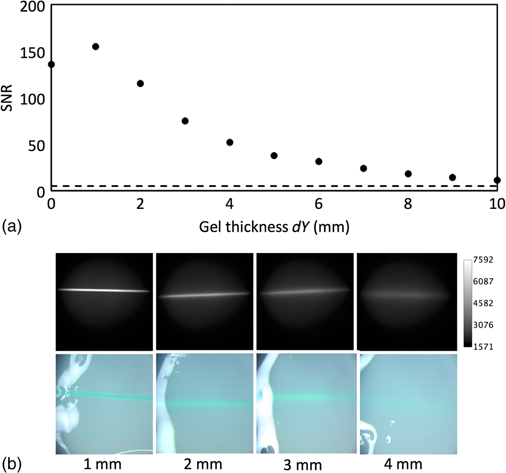 3.2.Demonstration of Augmented Imaging3.2.1.Color balance with augmented imagingA simple illustration of augmented microscopy is provided in Fig. 6. Images shown here represent the eyepiece view of the augmented microscope operating in (a) bright field, (b) NIR fluorescence, and (c) augmented configurations, producing real, synthetic, and composite images, respectively. In the augmented configuration, NIR fluorescence, not visible to the operator, is converted into green signal and overlaid with the bright-field image. White rings of light seen in some of the wells in Figs. 6(a) and 6(c) are reflections of the ring illuminator from the surface of the aqueous solution of the dye. 3.2.2.Near infrared laser beamAn 820-nm NIR laser beam was introduced into a handheld laser ablation wand and imaged with the microscope (Fig. 7). It can be seen that without NIR augmentation of the images, one cannot visualize the laser beam or the visible environment in the visible (a) and NIR (b) images, respectively. The augmented image (c) allows for complete visualization of treatment beam and visible environment. Fig. 7NIR laser light delivered through handheld laser wand for demonstration of NIR laser beam guidance by augmented microscope: (a) visible image conceals location of NIR laser beam, (b) NIR image lacks any spatial information, and (c) augmented image visualizes both NIR light and visible spatial ques.  3.2.3.In vivo imagingWe demonstrated image-guided surgery in anesthetized rats using the augmented microscope. First, the surgeon exposed the left carotid artery under the microscope operating in the bright-field mode. The working distance of 81 mm with magnification provided a field of view of 25 mm across, which is appropriate for this procedure. The synthetic channel was activated to generate superposition of bright field and NIR fluorescence. The ICG was injected and a bright green signal appeared in areas filled with ICG solution (Fig. 8 and Video 1). Examples of images generated in real time are shown in Fig. 8. The surgeon has the ability to control the brightness of the synthetic image (NIR fluorescence color coded in green) added on top of the real image (bright field). The image in Fig. 8(c) exemplifies a balance of these two. The composite image illustrated there is generated at 20 fps, enabling a video rate monitoring of ICG distribution. We estimate that with an NIR sensor format of and 25 mm field of view corresponding to magnification, blood vessels as small as in diameter can be visualized, and at magnification (i.e., human arterials are on the order of tens of micrometers). This spatial resolution is approaching the limit of optical resolution of the system operating at 820 nm with the NA 0.1 objective lens. Fig. 8Left rat carotid artery: (a) visible image, (b) NIR image, and (c) augmented image (also shown in Video 1). Ruler increments are 1 mm. Spatial differences between simultaneously acquired NIR and augmented images are a result of capturing these images at different microscope ports. ICG injection into rat model and visualization of carotid artery (Video 1 MOV, 12 MB) [URL: http://dx.doi.org/10.1117/1.JBO.20.10.106002.1]. 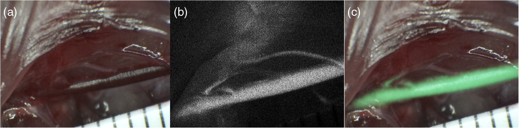 4.DiscussionWe described the practical realization of augmented microscopy, where bright-field images are superimposed with electronically processed images of NIR fluorescence of ICG within the optical path of the stereomicroscope. This augmented microscope is designed to produce such composite images in real time, under illumination conditions typically encountered in the operating room. Operating under luminance of 100,000 lx provided by a metal halide lamp and auxiliary LED lamps, and capturing NIR fluorescence at 20 Hz frame rate, the microscope can detect ICG concentrations down to 189 nM. Typical dose given to a patient is at least . We observed a linear relationship between the fluorescence intensity and ICG concentration within the range of (), with self-quenching becoming evident at higher concentrations. The concentration that produced maximal fluorescence emission () is different than that reported in the literature.22 This may be attributed to differences in experimental conditions as well as differences in specific serum albumin contributions to the fluorescence intensities observed by various authors. Even at higher concentrations of ICG, and , we observed a linear increase in fluorescence emission versus excitation power with no evidence of photobleaching. The SNR appeared to be lower for 0 mm gel depth compared to 1 mm gel depth. At 0 mm, the capillary tube is partially exposed at the air/gel interface, and this interface may in fact enhance forward and lateral scatter from the tube and gel with concomitant reduction in SNR, as observed in Fig. 5. Fluorescence images observed using the augmented microscope appear sharp and well defined (Figs. 4 and 8). This ensures accurate visualization of superficial anatomical structures. The ability to detect signal at greater depths within tissues may be beneficial for observing hidden structures of importance. At the same time, however, fluorescence from within a greater depth may contribute to diffuse images, displaying superimposed layers of fluorescence originating from various depths, similar to those shown in Fig. 5. Extracting useful information from such images may require further development of the instrument, including structured illumination or image processing. In its current realization, the augmented microscope was able to display augmented fluorescence images down to approximately 3 mm. Beyond this depth, structures are no longer discernable and fluorescence signal is diffused producing no useful anatomical information. The novelty of the presented augmented microscope is threefold: (1) NIR augmentation of bright-field images is provided within the optical path of a conventional stereomicroscope via an add-on module; (2) by utilizing the optical path of the stereomicroscope, we maintain full 3-D stereoscopic vision, lost in fully digital display systems; and (3) we retain the imaging environment familiar to surgeons, including integral features of surgical microscopes such as real-time magnification and focus adjustments, camera mounting, and multiuser access. The optical stereomicroscope remains a standard tool in neurosurgery and other surgical procedures. It retains all cues critical for 3-D perception: binocular disparity, motion parallax, convergence, and accommodative distance. A microscope-based intraoperative imaging system provides control of the magnification and the field of view while maintaining uninterrupted spatial coregistration and multiviewer access as required in many surgical applications of microscopes. The concept of the augmented stereomicroscope described here should be contrasted with stereoscopic rendition systems based on two cameras, often found in computer vision systems, including the da Vinci robotic system (Intuitive Surgical, Sunnyvale, California). Such electronic systems simplify image processing and overlays. In the implementation presented here, the microscope retains the full stereoscopic capability, with the bright-field (real) image being presented in both oculars. The false-colored NIR fluorescence (synthetic) image appears in only one ocular where it is superimposed with the matching channel of the bright-field image. Therefore, the primary cues for 3-D vision, convergence, and accommodation depth are completely defined by the bright-field image. We believe that this solution reduces strain and fatigue associated with fully electronic stereoscopic displays, such as that used in the da Vinci Surgical Systems, where the accommodative distance and the convergence angle are decoupled and are pointing to different spatial locations.23 Such distorted, even conflicting, spatial relations often contribute to fatigue and strain as well as subpar outcomes in certain performance tests.24,25 Also, our system will likely reduce the strain and fatigue in comparison to systems where the left and right oculars separately present the real and synthetic images, with no clear cues for spatial coregistration of these two types of images, such as the dual imaging color module (Leica Microsystems, AG). We envision that a fully developed augmented microscope will generate a stereoscopic composite image in both oculars, using separate NIR fluorescence images captured from the left and right optical paths of the microscope, providing complete and correct spatial cues for 3-D vision, therefore significantly reducing strain and fatigue. Developments of intraoperative NIR fluorescence imaging techniques may enable surgical manipulation while simultaneously monitoring distribution of NIR contrast agents. The augmented microscope described here uniquely addresses this need in many situations routinely requiring the use of specialized surgical microscopes, such as neurological, cerebrovascular, otolaryngological, and ophthalmic procedures. As such, it complements the ever-increasing range of superb commercial and research devices relying on the synthetic (predominantly false-colored NIR fluorescence) images projected on auxiliary monitors,26–28 wearable see-through display,29,30 or dynamic optical projection onto the surgical field31 introduced recently and excelling in their own applicable medical specialties. Procedures that traditionally are performed using surgical microscopes will likely benefit from image augmentation as we described in this report. In one example, we demonstrated FAAME, a technique in which the augmented microscope is employed to improve the performance of ICG videoangiography, to directly visualize the relationship between angiographic data and the tissue.19 ICG videoangiography has already become a standard element of vascular neurosurgeries.32 Therefore, the surgeon reviews the black and white angiography video loops displayed on a monitor to assess aneurysm and vessel patency, vascular architecture within the surgical field, obliteration status of arteriovenous pathology, direction of blood flow, and assessment of bypass grafts and collateral blood flow.33 FAAME merges existing imaging technologies to simultaneously present information available from an intraoperative angiogram within the ocular of the microscope, while maintaining full functionality of the surgical microscope.19 Another area of potential application of the augmented microscope is in surgical treatment of brain tumors. Current treatment modalities include surgical resection of tumors and their adjacent tissue, which often contains infiltrative neoplastic cells.34,35 Aggressive resection is associated with the risk of removing normal brain tissue and impairing functions of the patient. On the other hand, incomplete resection of tumor results in its immediate relapse in 90% of patients.33 Intraoperative NIR imaging may aid in resection of these challenging tumors.19,26–39 The long-term interest in the intraoperative NIR fluorescence visualization is driven by the development of new agents capable of improved delineation of brain tumor margins. Examples of dyes include various derivatives of NIR fluorescent dye currently undergoing preclinical or clinical evaluations, such as BLZ-100, a chlorotoxin-ICG conjugate;36,37 CLR1502, an alkylphopholine derivative of a cyanine dye;40,41 anti-EGFR antibody fragments conjugated to IRDye 800 CW;42,43 and others.44 We believe that the ability to simultaneously visualize the surgical field and contrast agent within the augmented microscope will enable broad implementation of image guidance in surgeries. The presented imaging system development is concerned with processing and display of NIR images, such as those obtained from fluorescence emission. Because scattering and absorptive properties of the tissue obscure fluorescence signal, various forms of data corrections may be required to yield quantitative diagnostic data related to the true distribution of NIR contrast agents in the tissue. Examples of such processing methods are discussed in the literature.45–47 These are generally based on some form of processing fluorescence and reflectance data, and may require acquisition of spectrally resolved images. Because the visible and NIR channels are separated in the presented design, processing images transmitted in the visible channel, 350 to 750 nm, would not affect functionality of augmentation; however, implementation of such processing may require further testing in the augmented microscope. The image augmentation we describe allows for seamless integration of such quantitative fluorescence images with the optical system of the microscope. The system has the ability to create image-processing scripts, such as arbitrary thresholding of live data before projecting the synthetic images through the augmentation module. With the possible implementation of color OLED, the thresholded data can also be color-coded in a user defined scheme. We envision that display of such quantitative fluorescence images could benefit from the color OLED display (in place of green monochrome OLED of the current microscope) to help highlight diagnostically relevant information. Future development of the augmented microscope will focus on introducing stereoscopic augmentation, whereby both channels of the stereoscopic microscope will produce the composite of real and synthetic images, with proper coregistration of left and right ocular images. In addition, we will explore applications of the augmented microscope in guiding laser surgery using an NIR laser beam, such as Ti:Sapph and Nd:YAG,48,49 as well as for superimposing other types of information, such as prerecorded magnetic resonance imaging images or single-point data readouts. AcknowledgmentsMR was supported by Grant No. CA120350 and JRW by Grant No. HL007955 both from the National Institutes of Health. MR and GML acknowledge support of the Harrison H. and Catherine C. Barrett Imaging Grant and the University of Arizona TRIF Optics/Imaging Program. JRW also acknowledges support from ARCS Foundation Crawford family donation. ReferencesA. L. Vahrmeijer et al.,
“Image-guided cancer surgery using near-infrared fluorescence,”
Nat. Rev. Clin. Oncol., 10
(9), 507
–518
(2013). http://dx.doi.org/10.1038/nrclinonc.2013.123 Google Scholar
S. Gioux, H. S. Choi and J. V. Frangioni,
“Image-guided surgery using invisible near-infrared light: fundamentals of clinical translation,”
Mol. Imaging, 9
(5), 237
–255
(2010). Google Scholar
R. K. Orosco, R. Y. Tsien and Q. T. Nguyen,
“Fluorescence imaging in surgery,”
IEEE Rev. Biomed. Eng., 6 178
–187
(2013). http://dx.doi.org/10.1109/RBME.2013.2240294 Google Scholar
R. C. Benson and H. A. Kues,
“Fluorescence properties of indocyanine green as related to angiography,”
Phys. Med. Biol., 23
(1), 159
–163
(1978). http://dx.doi.org/10.1088/0031-9155/23/1/017 PHMBA7 0031-9155 Google Scholar
A. Scerrati et al.,
“Indocyanine green video-angiography in neurosurgery: a glance beyond vascular applications,”
Clin. Neurol. Neurosurg., 124 106
–113
(2014). http://dx.doi.org/10.1016/j.clineuro.2014.06.032 CNNSBV 0303-8467 Google Scholar
N. L. Martirosyan et al.,
“Use of in vivo near-infrared laser confocal endomicroscopy with indocyanine green to detect the boundary of infiltrative tumor: laboratory investigation,”
J. Neurosurg., 115
(6), 1131
–1138
(2011). http://dx.doi.org/10.3171/2011.8.JNS11559 Google Scholar
J. T. Liu, D. Meza and N. Sanai,
“Trends in fluorescence image-guided surgery for gliomas,”
Neurosurgery, 75
(1), 61
–71
(2014). http://dx.doi.org/10.1227/NEU.0000000000000344 NEQUEB Google Scholar
Q. T. Nguyen and R. Y. Tsien,
“Fluorescence-guided surgery with live molecular navigation–a new cutting edge,”
Nat. Rev. Cancer, 13
(9), 653
–652
(2013). http://dx.doi.org/10.1038/nrc3566 NRCAC4 1474-175X Google Scholar
M. Kersten-Oertel, P. Jannin and D. L. Collins,
“The state of the art of visualization in mixed reality image guided surgery,”
Comput. Med. Imaging Graph., 37
(2), 98
–112
(2013). http://dx.doi.org/10.1016/j.compmedimag.2013.01.009 Google Scholar
A. M. De Grand and J. V. Frangioni,
“An operational near-infrared fluorescence imaging system prototype for large animal surgery,”
Technol. Cancer Res. Treat., 2
(6), 553
–562
(2003). http://dx.doi.org/10.1177/153303460300200607 Google Scholar
V. Ntziachristos, J. S. Yoo and G. M. van Dam,
“Current concepts and future perspectives on surgical optical imaging in cancer,”
J. Biomed. Opt., 15
(6), 066024
(2010). http://dx.doi.org/10.1117/1.3523364 JBOPFO 1083-3668 Google Scholar
S. Keereweer et al.,
“Optical image-guided surgery—where do we stand?,”
Mol. Imaging Biol., 13
(2), 199
–207
(2011). http://dx.doi.org/10.1007/s11307-010-0373-2 Google Scholar
R. Babu and D. C. Adamson,
“Fluorescence-guided malignant glioma resections,”
Curr. Drug Discov. Technol., 9
(4), 256
–267
(2012). http://dx.doi.org/10.2174/157016312803305915 Google Scholar
A. Raabe et al.,
“Prospective evaluation of surgical microscope-integrated intraoperative near-infrared indocyanine green videoangiography during aneurysm surgery,”
J. Neurosurg., 103
(6), 982
–989
(2005). http://dx.doi.org/10.3171/jns.2005.103.6.0982 Google Scholar
K. Cleary and T. M. Peters,
“Image-guided interventions: technology review and clinical applications,”
Annu. Rev. Biomed. Eng., 12 119
–142
(2010). http://dx.doi.org/10.1146/annurev-bioeng-070909-105249 ARBEF7 1523-9829 Google Scholar
M. Behbahaninia et al.,
“Intraoperative fluorescent imaging of intracranial tumors: a review,”
Clin. Neurol. Neurosurg., 115
(5), 517
–528
(2013). http://dx.doi.org/10.1016/j.clineuro.2013.02.019 CNNSBV 0303-8467 Google Scholar
C. F. Gainer, C. de Silva and M. Romanowski,
“Augmented microscopy-simultaneous acquisition of bright field and luminescence lifetime images,”
Am. Soc. Laser Med. Surg.,
(2010). Google Scholar
J. R. Watson et al.,
“Augmented microscopy with near infrared fluorescence detection,”
Proc. SPIE, 9311 93110I
(2015). http://dx.doi.org/10.1117/12.2077008 PSISDG 0277-786X Google Scholar
N. L. Martirosyan et al.,
“Integration of indocyanine green videoangiography with operative microscope: augmented reality for interactive assessment of vascular structures and blood flow,”
Neurosurgery, 11 252
–257
(2015). http://dx.doi.org/10.1227/NEU.0000000000000681 NEQUEB Google Scholar
T. S. Troutman, J. K. Barton and M. Romanowski,
“Optical coherence tomography with plasmon resonant nanorods of gold,”
Opt. Lett., 32
(11), 1438
–1440
(2007). http://dx.doi.org/10.1364/OL.32.001438 OPLEDP 0146-9592 Google Scholar
A. N. Yaroslavsky et al.,
“Optical properties of selected native and coagulated human brain tissues in vitro in the visible and near infrared spectral range,”
Phys. Med. Biol., 47
(12), 2059
–2073
(2002). http://dx.doi.org/10.1088/0031-9155/47/12/305 PHMBA7 0031-9155 Google Scholar
M. Weiler, T. Kassis and J. B. Dixo,
“Sensitivity analysis of near-infrared functional lymphatic imaging,”
J. Biomed. Opt., 17
(6), 066019
(2012). http://dx.doi.org/10.1117/1.JBO.17.6.066019 JBOPFO 1083-3668 Google Scholar
R. T. Held and T. T. Hui,
“A guide to stereoscopic 3D displays in medicine,”
Acad. Radiol., 18
(8), 1035
–1048
(2011). http://dx.doi.org/10.1016/j.acra.2011.04.005 Google Scholar
S. M. Brown et al.,
“Three-dimensional endoscopic sinus surgery: feasibility and technical aspects,”
Otolaryngol. Head Neck Surg., 138
(3), 400
–402
(2008). http://dx.doi.org/10.1016/j.otohns.2007.12.007 Google Scholar
A. Sengül et al.,
“Role of holographic displays and stereovision displays in patient safety and robotic surgery,”
Intelligent Autonomous Systems 12, 143
–154 Springer, Berlin, Heidelberg
(2013). Google Scholar
S. L. Troyan et al.,
“The FLARE™ intraoperative near-infrared fluorescence imaging system: a first-in-human clinical trial in breast cancer sentinel lymph node mapping,”
Ann. Surg. Oncol., 16
(10), 2943
–2952
(2009). http://dx.doi.org/10.1245/s10434-009-0594-2 Google Scholar
J. R. van der Vorst et al.,
“Near-infrared fluorescence imaging of liver metastases in rats using indocyanine green,”
J. Surg. Res., 174
(2), 266
–271
(2012). http://dx.doi.org/10.1016/j.jss.2011.01.009 JSGRA2 0022-4804 Google Scholar
A. M. Mohs et al.,
“An integrated widefield imaging and spectroscopy system for contrast-enhanced, image-guided resection of tumors,”
IEEE Trans. Biomed. Eng., 62
(5), 1416
–1424
(2015). http://dx.doi.org/10.1109/TBME.2015.2389626 IEBEAX 0018-9294 Google Scholar
Y. Liu et al.,
“Hands-free, wireless goggles for near-infrared fluorescence and real-time image-guided surgery,”
Surgery, 149
(5), 689
–698
(2011). http://dx.doi.org/10.1016/j.surg.2011.02.007 SURGAZ 0039-6060 Google Scholar
Y. Liu et al.,
“Near-infrared fluorescence goggle system with complementary metal-oxide–semiconductor imaging sensor and see-through display,”
J. Biomed. Opt., 18
(10), 101303
(2013). http://dx.doi.org/10.1117/1.JBO.18.10.101303 JBOPFO 1083-3668 Google Scholar
P. Sarder et al.,
“Dynamic optical projection of acquired luminescence for aiding oncologic surgery,”
J. Biomed. Opt., 18
(12), 120501
(2013). http://dx.doi.org/10.1117/1.JBO.18.12.120501 JBOPFO 1083-3668 Google Scholar
A. Raabe et al.,
“Near-infrared indocyanine green video angiography: a new method for intraoperative assessment of vascular flow,”
Neurosurgery, 52
(1), 132
–139
(2003). NEQUEB Google Scholar
A. Raabe et al.,
“Prospective evaluation of surgical microscope-integrated intraoperative near-infrared indocyanine green videoangiography during aneurysm surgery,”
J. Neurosurg., 103
(6), 982
–989
(2005). http://dx.doi.org/10.3171/jns.2005.103.6.0982 JONSAC 0022-3085 Google Scholar
A. F. Eichler et al.,
“The biology of brain metastases-translation to new therapies,”
Nat. Rev. Clin. Oncol., 8
(6), 344
–356
(2011). http://dx.doi.org/10.1038/nrclinonc.2011.58 Google Scholar
M. Mut,
“Surgical treatment of brain metastasis: a review,”
Clin. Neurol. Neurosurg., 114
(1), 1
–8
(2012). http://dx.doi.org/10.1016/j.clineuro.2011.10.013 CNNSBV 0303-8467 Google Scholar
P. V. Butte et al.,
“Near-infrared imaging of brain tumors using the tumor paint BLZ-100 to achieve near-complete resection of brain tumors,”
Neurosurg. Focus, 36
(2), E1
(2014). http://dx.doi.org/10.3171/2013.11.FOCUS13497 Google Scholar
D. S. Kittle et al.,
“Fluorescence-guided tumor visualization using the tumor paint BLZ-100,”
Cureus, 6
(9),
(2014). http://dx.doi.org/10.7759/cureus.210 Google Scholar
K. Sexton et al.,
“Pulsed-light imaging for fluorescence guided surgery under normal room lighting,”
Opt. Lett., 38
(17), 3249
–3252
(2013). http://dx.doi.org/10.1364/OL.38.003249 OPLEDP 0146-9592 Google Scholar
P. A. Valdés et al.,
“Quantitative, spectrally-resolved intraoperative fluorescence imaging for neurosurgical guidance in brain tumor surgery: pre-clinical and clinical results,”
Proc. SPIE, 8928 892809
(2014). http://dx.doi.org/10.1117/12.2039090 PSISDG 0277-786X Google Scholar
M. L. Korb et al.,
“Breast cancer imaging using the near-infrared fluorescent agent, CLR1502,”
Mol. Imaging, 13 1
–9
(2014). http://dx.doi.org/10.2310/7290.2014.00040 Google Scholar
K. I. Swanson et al.,
“Fluorescent cancer-selective alkylphosphocholine analogs for intraoperative glioma detection,”
Neurosurgery, 76
(2), 115
–124
(2015). http://dx.doi.org/10.1227/NEU.0000000000000622 NEQUEB Google Scholar
K. Sexton et al.,
“Fluorescent affibody peptide penetration in glioma margin is superior to full antibody,”
PLoS One, 8
(4), e60390
(2013). http://dx.doi.org/10.1371/journal.pone.0060390 POLNCL 1932-6203 Google Scholar
R. W. Holt et al.,
“Tomography of epidermal growth factor receptor binding to fluorescent affibody in vivo studied with magnetic resonance guided fluorescence recovery in varying orthotopic glioma sizes,”
J. Biomed. Opt., 20
(2), 026001
(2015). http://dx.doi.org/10.1117/1.JBO.20.2.026001 JBOPFO 1083-3668 Google Scholar
J. T. Liu et al.,
“Trends in fluorescence image guided surgery for gliomas,”
Neurosurgery, 75
(1), 61
–71
(2014). http://dx.doi.org/10.1227/NEU.0000000000000344 NEQUEB Google Scholar
A. Bogaards et al.,
“In vivo quantification of fluorescent molecular markers in real-time by ratio imaging for diagnostic screening and image-guided surgery,”
Lasers Surg. Med., 39
(7), 605
–613
(2007). http://dx.doi.org/10.1002/lsm.20525 LSMEDI 0196-8092 Google Scholar
R. B. Saager et al.,
“Quantitative fluorescence imaging of protoporphyrin IX through determination of tissue optical properties in the spatial frequency domain,”
J. Biomed. Opt., 16
(12), 126013
(2011). http://dx.doi.org/10.1117/1.3665440 JBOPFO 1083-3668 Google Scholar
P. A. Valdés et al.,
“Quantitative, spectrally-resolved intraoperative fluorescence imaging,”
Sci. Rep., 2 798
(2012). http://dx.doi.org/10.1038/srep00798 SRCEC3 2045-2322 Google Scholar
J. Nguyen et al.,
“Sub-surface, micrometer-scale incisions produced in rodent cortex using tightly-focused femtosecond laser pulses,”
Lasers Surg. Med., 43
(5), 382
–391
(2011). http://dx.doi.org/10.1002/lsm.21054 LSMEDI 0196-8092 Google Scholar
V. H. Romero et al.,
“Nanoparticle assisted photothermal deformation of individual neuronal organelles and cells,”
Biomed. Opt. Express, 5
(11), 4002
–4012
(2014). http://dx.doi.org/10.1364/BOE.5.004002 BOEICL 2156-7085 Google Scholar
BiographyJeffrey R. Watson is a PhD candidate in biomedical engineering at the University of Arizona. He completed his BS at Northern Arizona University in 2012. His research interest includes optical imaging modalities for visualizing and guiding light-based therapies, and biomedical imaging and optical spectroscopy of nanomaterials. Christian F. Gainer received his PhD in biomedical engineering from the University of Arizona in 2013. Currently, he is an associate specialist for the Vision Science Program at the University of California at Berkeley. He provides imaging support for the program while researching new light microscopy and image analysis methods for use in vision research. Nikolay Martirosyan is a neurosurgery resident in the Department of Surgery at the University of Arizona and a PhD candidate in neuroscience at Arizona State University. He completed his MD in Moscow in 2005. He continued his training at the Burdenko Neurological Institute in Moscow and Barrow Neurological Institute in Phoenix. His research and clinical interests include spinal cord and spinal trauma, pathophysiology of blood flow, and intraoperative optical imaging of brain tumors. Jesse Skoch is the pediatric neurosurgery fellow at the Cincinnati Children’s Hospital. He obtained his MD in 2009 from the University of Colorado and completed residency training at the University of Arizona in 2015. His clinical interests include the surgical treatment of epilepsy, brain tumors, and spinal deformity. His research interests are to better understand hydrocephalus and to improve treatment through bio-engineering approaches as well as developing imaging techniques to improve brain tumor removal. G. Michael Lemole, Jr. is a professor of surgery and chief of the Division of Neurosurgery at the University of Arizona, Department of Surgery. He completed his MD at the University of Pennsylvania in 1995 and residency at the Barrow Neurological Institute in 2002. His clinical expertise includes all aspects of skull base disease, including minimally invasive endoscopic techniques, classical approaches, and radiosurgical treatments. His research interests include brain tumor markers, skull base surgery device development, and neurosurgical education. Rein Anton is an assistant professor of neurosurgery in the Department of Surgery at the University of Arizona. He obtained his MD from the Tartu University, Estonia, in 1977 and his PhD in brain tumor biochemistry in 1984, followed by postdoctoral training at Uppsala University and neurosurgery residency at Loma Linda completed in 1999. His clinical expertise is in spine disorders and their surgical treatments. His research interests include brain tumors, Parkinson's disease, and spine biomechanics. Marek Romanowski is an associate professor in the Department of Biomedical Engineering at the University of Arizona. He obtained his PhD in physics in 1989 from Copernicus University in Poland. After completing postdoctoral training at Johns Hopkins and the University of Arizona, he directed research in drug delivery in the commercial sector. He joined the biomedical engineering faculty in 2004, where he pursues his interest in optical spectroscopy, nanomaterials, and optical imaging for biomedical applications. |


