
|
|
1.IntroductionDiabetes mellitus is a common health issue in most developed and developing countries. As monitoring of glucose is the most effective solution for standard diabetes care, frequent monitoring can reduce disease severities, secondary complications, related mortalities, and aid in maintaining the body’s insulin level.1 Clinical analysis is the best way to accurately determine the level of blood glucose. However, as multiple glucose analyses and rapid monitoring are required, self-monitoring of glucose levels is preferred. In this respect, many glucose monitors have been developed using various approaches, such as enzymatic analysis, electrochemical measurement, and continuous glucose measurement through both invasive and noninvasive methods in order to satisfy the demand. Enzymatic analysis is the most valuable analytical assay due to its high specificity; it does not respond to any other physiological fluids. Moreover, optical glucose sensors of porous gel sensor,2 optical strip sensor,3 and nanoprism sensor4 have been reported as effective sensors with enzymatic analysis. However, their complication is that the readout of the results is analog. Hence, electrochemical-based amperometric glucose sensors are the most appealing type of sensors due to their user-friendly and digital output. However, interferences with nonspecific electroactive particles combined with complications related to signal conversion between the enzyme and mediator are two disadvantages of the sensors.5,6 Importantly, accurate and user-friendly glucose monitoring is essential to control diabetic complications. Accordingly, we were motivated to develop an enzymatic glucose sensor with a digital read out signal. The present research group found that CMOS image sensor-based whole blood glucose analysis is one of the most efficient methods due to its digital output, real-time monitoring and high availability in mobile phone cameras, which is a huge added advantage. Usually, the CMOS image sensors use as a digital camera, microprocessors, and sensor elements;7 nowadays, the CMOS sensors participate in the generation of the protein/peptide array and DNA array.8–10 Also, we have successfully accomplished CMOS image sensor-based antigen–antibody interactions.11–14 In addition, CMOS image sensors employing various glucose monitoring methods, including continuous glucose monitoring method,15,16 enzymatic glucose monitoring method,17,18 and thermal-based glucose monitoring,19 operate at the in vitro and in vivo levels. In addition, smartphones have proved efficient for calorimetric analysis. Therein, Oncescu et al. demonstrated smartphone-based biomarker monitoring for hydration, electrolyte loss, and enamel decalcification using sweat and saliva.20 A light-emitting diode (LED) array integrated smartphone camera has been utilized as a hand-held microplate reader for enzyme-linked immunosorbent assays (ELISA).21 Moreover, a smartphone camera analyzed the color intensity of a 3-D reaction platform to quantify the glucose level; the analysis takes 7 min to read out the data.22 Also, our previous study performed smartphone camera-based mouse plasma glucose monitoring as a photon–detection technique.18 Such positive outcomes have motivated us to continue the study with whole blood glucose analysis. According to the research report, nanomaterials and microparticles play major roles in electrochemical and enzymatic glucose sensors.23 Similarly, we have utilized silica nanoparticles for enzymatic glucose measurement due to their chemical inertness, optical transparency, low temperature encapsulation, thermal stability, and biocompatibility.24 Particularly, glucose oxidase (GOX) enzyme and chromogen could be immobilized on amine-functionalized silica nanoparticles () through electrostatic attraction.25,26 In the present study, a CMOS image sensor was used as a bioanalytical device for the measurement of blood glucose levels. For the analysis, 28 mouse whole blood samples were applied to the poly-ethylene terephthalate (PET) chip, and filtered plasma was flowed over the reaction area. The oxidized glucose produced the green color based on the glucose concentration.27 The CMOS image sensor that measures the glucose level based on the color intensity is an original point that differentiates this work from others. In addition, the study demonstrated fabrication of a PET chip that is technically suitable for a CMOS sensor-based monitoring system, synthesis of nanoparticles, immobilization of assay reagent on PET film, enzyme stability and activity, blood plasma separation that is reproducible and user friendly. As a result, a CMOS image sensor-based real-time whole blood glucose monitoring system reached the clinical standard. A wide range of photophysical techniques such as UV-spectral absorbance, dynamic light scattering (DLS), Fourier transform-infrared spectroscopy (FTIR), x-ray diffraction (XRD), and field emission scanning electron microscopic (FE-SEM) imagery were used to characterize various aspects, including nanoparticle size and distribution, enzyme immobilized nanoparticles, absorbance of assay reagent immobilized nanoparticles, and differences between bare and enzyme-immobilized chips. Positive outcomes motivated the fabrication of a PET chip for enzyme kinetic blood glucose analysis using a CMOS image sensor. This study provides a simple and precise approach for a blood glucose monitoring system by point-of-care (POC) approach. 2.Materials and Methods2.1.CMOS Image Sensor and InstrumentationA CMOS image sensor (Sponsored from Silicon File Technologies) is an electronic device that converts electrons into digital numbers. In the present experiment, a NOON0PC30L, 110,000 active single chip CMOS image sensor was used. The sensor contains multi pixel photon arrays and is connected to a 10-bit analog-to-digital converter (ADC). The photodiode absorbs photons from living room lights and they are converted as electrons into a digital number by the ADC. Moreover, FE-SEM (JEOL-ISM-7500F; JEOL, Tokyo, Japan) images and the DLS method (Malvern Instruments Korea, Seoul, Republic of Korea) were used to confirm the average particle size of nanoparticles and their distribution. Electrophoretic light scattering spectrophotometer (ELS-800; Japan) was used to measure the zeta potential or overall surface charge of the nanoparticles. Furthermore, a UV-spectral study (Carry Win Spectrophotometer) determined the absorbance of the nanoparticles before and after assay reagent immobilization and oxidation. Three individual samples were used for each spectral analysis at 25°C. XRD analysis (Model D/Max-2200; Rigaku, Woodlands, Texas) was used to identify the crystallites of the synthesized nanoparticles and the reacted sample. Functional groups were recorded by an FTIR spectroscopy (TENSOR 27 instrument, Bruker Optics, Alexandria, NSW, Australia) for nanoparticles before and after enzyme immobilization and oxidation. 2.2.Synthesis of NanoparticlesFor nanoparticle synthesis, 6.16 ml of ammonia (), of 3-aminopropyl triethoxysilane (APTES), and 4.48 ml of distilled water (DI) were added to 6.95 ml of ethanol and then stirred for 1 h using a magnetic stirrer. Then 2.5 ml of TEOS was applied to the mixture drop wise using an injection pump (flow rate: ) and it was stirred for 24 h. The silica colloids were recovered by high speed centrifugation. Then the solutions were dialyzed with ethanol and deionized (DI) water to remove unreactive materials. The collected nanoparticles were mixed with assay reagent before being applied to the hydrophilic PET film. 2.3.Preparation of Assay ReagentGlucose oxidase (GOD) (), peroxidase (POD) (), and 35 mM chromogen of 2, 2’-azino-bis (3-ethylbenzothiazoline-6-sulphonic acid) (ABTS) were purchased from Sigma Aldrich, and reagents were prepared at their respective concentrations using standard laboratory procedures. All solutions were prepared and stored in the refrigerator until use. The enzymes and chromogen were mixed at 2:2:1 volume ratios. The required amount () of assay reagent was added onto nanoparticles to induce the interaction between the assay reagent and nanoparticles. 2.4.Blood Collection from MouseEight-week-old male C57BL/6J mice were purchased from Charles River Laboratories, Japan. The mice were housed under controlled temperature () and 12 h light/dark cycle with free access to water and a regular diet (PicoLab Rodent Diet 20, #5053, LabDiet). After 1 week acclimation period, mice were divided into two groups and fed either a regular diet or a 60% high fat diet (HFD) (D12492, Research Diet) for 4 weeks. At 13 weeks of age, to test various levels of blood glucose, glucose ( body weight) was intraperitoneally administrated in 16 h overnight-fasting mice and blood was collected from the tail vein at 0, 15, 30, 60, 90, 120, 140, and 160 min (). A lower concentration of glucose analysis was carried out with 20 h fasting mice and 5-h fasting mice. Glucose concentration was analyzed using whole blood by a glucose oxidase method on a GM9 glucose analyzer II (Analox, London) and CMOS-based measurements. All the experiments were performed in compliance with the relevant laws and institutional guidelines and also in accordance with the institutional Center of Animal Care and Use Committee of Lee Gil Ya Cancer and Diabetes Institute, Gachon University. For the CMOS analysis,28 mice having different glucose concentrations were used for glucose analysis. The whole blood collection schedule and concentrations of glucose are given in Table 1. Table 1Whole blood collection schedule from RC and high fat diet (HFD) mice before and after being fed IpGTT.
Note: Blood was not collected from HRD mice at 5 h fasting and after feeding –140 min (fasting blood glucose: FBG; feeding blood glucose: FeBG) 2.5.Chip Fabrication for Glucose AnalysisA simple disposable chip was fabricated by using hydrophilic PET film. Sample pad and plasma separation membranes were used to filter the plasma from whole blood, and the absorption pad was used to absorb excess plasma or an oxidized sample. The size of the reaction area with a capacity of was developed in the bottom layer of the PET film (). Assay reagent immobilized on nanoparticles was dispensed over the reaction area of the hydrophilic PET film, which was stored in the refrigerator until use. To fabricate the chip, a size of a hydrophilic PET film was fixed over the bottom layer of the PET film, as shown in Fig. 1. Both lateral edges of the top layer were strongly fixed on the bottom layer of the PET film by a double-sided adhesive layer, which increases the capillary action. This was followed by a absorption pad, which was fixed at the right end of the chip, and was made of cellulose fiber with a high absorption capacity. One edge of the plasma separation membrane () was fixed on the left side of the bottom layer while the other end overlapped the top layer of the PET film. Four edges of the separation layer were pasted on the PET film. The plasma separation membrane gently touched the bottom layer for easy and rapid sample flow to the reaction area. The sample pad was fixed and pasted at the edge of the bottom layer. A schematic illustration of the glucose chip is shown in Fig. 1, layer by layer. Previously, various types of glucose chips were prepared for whole blood glucose analysis that exhibited filtration defects, time consuming kinetic reaction, and less photon sensitivity. Finally, a chip was fabricated without any defects along with a high sensitivity to the respective analysis method. Fig. 1Fabrication of hydrophilic poly-ethylene terephthalate (PET) film chip for whole blood glucose analysis. Assay reagent immobilized amine functionalized silica () nanoparticles are coated on the bottom layer of the PET film and the reaction area is covered with a top layer for capillary action. Then the plasma separation membrane, sample pad, and absorption pad arer fixed to make a fully fabricated chip. Each membrane has been fixed by a double sided adhesive layer. 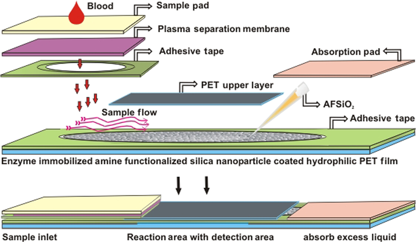 2.6.Glucose Assay in Disposable Poly-Ethylene Terephthalate ChipFor the glucose assay, assay reagent immobilized nanoparticles () were dispensed over the reaction area before fixing the top layer of the PET film. A hydrophilic PET film ensured uniform immobilization over the entire reaction area. absorbed the water content of the assay reagent, and the amine group kept the enzymes from leaching. The enzyme immobilized nanoparticles helped to develop the chip as a semi-transparent substrate, which eradicates the scattering effect and produces consistent photon transmission. The fully fabricated chip was kept in a refrigerator until use. Twenty-eight whole blood samples were collected from normal and HFD mice and applied to individual glucose chips. Cell debris and blood cells were captured by the sample pad and plasma separation membrane, respectively. The plasma separation membrane could filter about 90% of the plasma, which was more pure than that obtained by centrifugation. Filtered plasma flowed onto the bottom layer of the chip as well as over the reaction area due to capillary action. Plasma glucose reacted well with the assay reagent for 1 to 2 min. An excess amount of sample flowed over the chip and was absorbed by the absorption pad. Each concentration of glucose produced a different intensity of green color that could be observed by the naked eye. Each chip was quantitatively analyzed by the CMOS image sensor. 2.7.Biochemical Analysis for Enzyme Activity and Stability to the ChipThe enzyme activity and stability of the chip was analyzed by a CMOS image sensor. To determine the specificity and sensitivity, different aqueous sugars were analyzed in the chip including galactose, sucrose, and lactose. Analyses were independently performed on the chip three times. To determine the thermal stability of the immobilized assay reagent, five different concentrations of the whole blood glucose such as 110, 163, 262, 416, and were used. The assay reagent immobilized chip was kept in a hot air oven at 20, 30, 40, 50, 60, and 70°C for 1 h and then the glucose oxidation was carried out and analyzed by the CMOS image sensor. To determine the pH stability of the chip, assay reagent was dissolved in the phosphate buffer with pHs of 2.0, 3.0, 4.0, 5.0, 6.0, 7.0, 8.0, and 9.0. For the analysis, five different concentrations of whole blood glucose samples were used as previously mentioned. Moreover, the glucose chip’s storage stability was analyzed with a 6 months incubated chip. Five chips were used to analyze the glucose oxidation with various concentrations of blood glucose, such as 178, 249, 308, 388, and . The CMOS image sensor measured the color intensity changes and proved the photon number variation. 3.Results and Discussion3.1.Surface Charge and Surface Morphological AnalysisAssay reagents immobilized on nanoparticles as electrostatic interactions and were spread over the hydrophilic PET film easily and uniformly. The interactions between nanoparticles and assay regents were confirmed by the zeta potential. The zeta potential has shown around for nanoparticles since the presence of a positively charged amine group was found on the surface and the zeta potential decreased to for negatively charged assay reagent. FE-SEM analysis was carried out to find the fundamental characterization of surface morphology of the chip. Thereby, nanoparticles, enzyme-immobilized nanoparticles, and oxidized nanoparticles were observed by SEM, as shown in Fig. 2. Figures 2(a)–2(c) show the uniform distribution of nanoparticles that adsorbed as two layers on PET film. The particle size was around 150 nm in each film. The reaction area of the chip images is presented in Figs. 2(e)–2(g), which proves the differences between nanoparticles and assay reagent immobilized nanoparticles. The enzyme immobilized film had a thin layer formation on nanoparticles as well as a thick layer formation after glucose oxidation. The FE-SEM images confirmed the interactions between assay reagent- nanoparticles and proved their adhesion over the film. Moreover, Figs. 2(d) and 2(h) show the DLS analysis at 633 nm and a scattering angle of 90°C. The data confirm a particle size of for nanoparticles, and the size increased to after enzyme immobilization on nanoparticles. The DLS data proved the assay reagent immobilization on nanoparticles by particle size increment. Fig. 2Field emission scanning electron microscopic (FE-SEM) images of nanoparticles immobilized on PET film. (a) Uniform particle distribution of nanoparticles on the PET film. (b) Two-layer formation on the PET film with uniform distribution. (c) Particle size was uniform and the nanoparticles size was 150 nm. (d) DLS estimation of nanoparticle: measurements were performed before mixing an enzyme in the nanoparticles; the particle size is . (e) Enzyme-immobilized nanoparticles on PET film. (f) Uniform enzyme immobilization on nanoparticles as a thin layer. (g) Oxidized glucose on nanoparticles immobilized on a PET chip. (h) Dynamic light scattering (DLS) estimation of nanoparticle-enzyme complexes: measurements were performed after mixing an enzyme in nanoparticles and the size was .  3.2.Ultraviloet-Spectral AnalysisFigure 3(i) shows the UV-visible absorbance spectrum of nanoparticles, assay reagent immobilized nanoparticles, and oxidized glucose. The analysis was carried out to find the level of interaction between the assay reagent, nanoparticles, and oxidized glucose which displayed an absorbance in the region from 200 to 800 nm. The absorption curve for nanoparticles showed a hump at 210 nm due to the localized surface plasmon of nanosized particles. The assay reagent showed two peaks at 350 and 400 nm; also, the assay reagent immobilized nanoparticles showed broader peaks at 400 nm and the absence of peaks at 350 nm. There was a peak shift to 405 nm, and additional peaks developed at 560 nm after glucose oxidation. This result confirms the effective interaction between the assay reagent and nanoparticles; it also proves that the interactions of the assay reagent immobilized nanoparticles were not influenced by the quality of glucose oxidation on the chip. Moreover, nanoparticles have various biological applications such as optical sensing, bio adsorption, and biocompatibility. Fig. 3UV-spectral absorbance and Fourier transform-infrared spectroscopy (FTIR) spectra analysis before and after glucose oxidation; (i) The ultraviolet (UV) spectrum shows the nanoparticles, assay reagent, assay reagent-immobilized nanoparticles, and oxidized glucose. Peak shift identified at 405 nm and additional peak developed at 560 nm after glucose oxidation. (ii) FTIR spectra analysis before and after the reaction: (a) hydrophilic PET film, (b) nanoparticles, (c) assay reagent immobilized on nanoparticles, (d) oxidized glucose, (e) chip stability after 20 days. The FTIR results prove the structural and functional properties of a glucose chip are stable after immobilization and oxidation.  3.3.Fourier Transform-Infrared Spectroscopy Structural AnalysisStructural information and interactions were studied for bare hydrophilic PET film, an nanoparticle coated film, the assay reagent immobilized film, and oxidized glucose films by FTIR, which are shown in Fig. 3(ii). Generally, hydrophilic PET film peak absorption energy considerably increased at , including a benzene ring (721), primary alcohol (1085 and 1013), and hybrid sp2 [1233 and (1707)]. Absorbance signals at were assigned to the asymmetrical stretching vibration of .27,29 The 2-Methacryloyloxyethyl phosphorylcholine unit featured one phosphor atom, an organic acid , and an inorganic acid on both sides of the molecules structures, directly improving the hydrophilicity.30 The spectrum of the hydrophilic PET film showed almost the same characteristic bands as the present study. The peak at indicates asymmetric stretching vibrations, whereas was assigned to symmetric stretching vibrations. The peak at was assigned to ν () of a free silanol group.31–34 Moreover, a new sharp peak was identified at , which indicates the presence of nanoparticles.33 Figure 3(ii) c almost shows the same peak as the nanoparticles, and new peaks at 1563 and indicate assay reagent immobilized successfully on . New sharp and moderate peaks appeared at 1556 and , which seem to indicate oxidized plasma glucose and other substances in the plasma. The assay reagent immobilized chip was analyzed after 20 days to confirm the stability of the assay reagent. There was no alteration of the characteristic peaks in the respective image of Fig. 3(ii) e, which supports chip stability. The structural information and interactions on bare hydrophilic PET film, nanoparticle coated film, enzyme immobilized chip, oxidized glucose chip, and chip stability results prove that there was no alteration in their characteristic peak after interactions on the PET film, which does not affect the glucose oxidation. All these characterization studies have proven the nanoparticle chip suitable for CMOS image-based whole blood glucose sensing. The intensive characteristic absorption peaks were observed in the liquid stage, while a new sharp peak appeared in the liquid stage of the sample at , indicating the amine groups in the nanoparticle suspension.35 Moreover, sharp peaks appeared at 2960 and , which indicate assay reagent immobilized on nanoparticles in molecular water (data not shown). Based on these functional groups, we were able to understand the structural vibrations of nanoparticles, enzyme immobilized , and oxidized glucose; their functional groups were not affected when bonded on the chip. 3.4.X-Ray Diffraction AnalysisFigure 4 shows the XRD patterns of the hydrophilic PET film before and after enzyme immobilized films. XRD patterns of the hydrophilic PET film show a broader peak in the range of and 25 deg, which can be allotted to the semi-crystalline structure of the PET film or an extrusion process in the production of the PET film.36 A sharp peak occurs in the range of and 25 deg, indicating the microcrystalline structure of the nanoparticles, and the intensity decreased gradually after assay reagent immobilization. The broader peaks identified at and 25 deg indicate semi-crystallites for enzyme-immobilized and oxidized glucose substrates, which show that the immobilized enzyme did not alter the structure of the nanoparticles.37 The results corroborated other related studies on enzyme immobilized nanoparticles adsorbed to PET film and oxidized glucose. 3.5.Photon Analysis by Smartphone Camera ModuleSuitable chip fabrication is an important part to this study. The hydrophilic PET film surface was suitable for coupling with the nanoparticle layer. Amine groups could bind the negatively charged enzymes via the electrostatic interactions that helped to develop the technically suitable chip for analysis by CMOS image sensor. Further, the characterization study proves the nanoparticle-based PET chip is suitable for glucose analysis. The CMOS image sensor analyzed the chip before and after glucose oxidation. Each CMOS image sensor contains a single photodiode to absorb the photons and convert them into the electrical energy via the photo electric effect. The electrical energy is converted into a digital number, which is directly proportional to the number of photon hits on sensor surface. Thereby, the photon number reduces any object exposed on the sensor. This simple concept creates the impacts on the POC glucose monitoring. Before measurement, the calibration value was fixed in the CMOS image sensor by adjusting the exposure time and analog gain value instead of by maximizing the background light intensity. Then an assay reagent added chip was exposed on the sensor, and the value was fixed as a reference value (175 A.U). In the glucose reaction, plasma glucose reacted with GOX, producing gluconic acid and . Following this, reacted with 2, 2’-azino-bis (3-ethylbenzothiazoline-6-sulphonic acid) (ABTS) in the presence of POD. Oxidized ABTS produced a green color product based on the glucose concentration through the enzyme kinetic reaction, which is shown in Fig. 5(a). Previously, our group carried out the glucose analysis from to successfully using the aforementioned reaction that proved the lower and upper limits of glucose detection.17 Figure 5(b) shows the schematic of glucose oxidation on the PET chip and monitoring by the CMOS image sensor as a photon-detection technique. For the analysis, 28 PET film chips were analyzed, and each chip produced a different color intensity based on the glucose concentration. Variations in color intensity at different glucose concentrations are shown in Fig. 5(c). The lower the concentration of glucose, the paler the color after oxidation with ABTS, and the color intensity increased with a higher concentration of glucose. Similarly, different concentrations of glucose produce different photon numbers based on the color intensity. A lower color intensity allowed the passing of more photons, and a higher color intensity allowed the passing of fewer photons. Thereby, the photon value decreased when the glucose concentration increased. In other words, the photon number decreased when the color intensity increased. The measured digital output of the photon value is shown in Fig. 6(a) for each individual glucose concentration. The experiment was performed thrice, and the average value is given. The photon value was 161 A.U at a low glucose concentration of , and the value linearly decreased to 31 A.U. at the highest concentration of . The change of photon value was linearly correlated to the glucose concentration, and the value was standard and consistent for each experiment. Even small differences of glucose concentrations could change the photon number. The relative oxidation level shown in Fig. 6(b) displays the cumulative value for each concentration of glucose. The relative oxidation level was calculated by subtracting the oxidized glucose value from the chip value. In addition, the CMOS image sensor could measure the glucose levels in mouse whole blood with an accuracy comparable to that of an Accu-Chek sensor, a glucose monitor that is commonly used in diabetes testing. The linearity graph as shown as Fig. 6(c) demonstrates the concentration linearity of the GM9 glucose analyzer and Accu-Chek sensor, whereas Fig. 6(d) shows the linearity of the CMOS image sensor-based photon value to quantify the accuracy. Moreover, the correlation coefficient () value was 0.9675 as a CMOS-based digital output value and 0.9712 for the glucose concentration. The comparison study with other glucose sensors proved the CMOS image sensor-based glucose monitoring system could be applicable for clinical diagnoses to determine blood glucose levels. Fig. 5CMOS image sensor-based glucose analysis. (a) Glucose assay by enzyme kinetic method. (b) Schematic representation shows the blood sample reacted with the immobilized assay reagent and developed color, followed by the glucose oxidized chip being monitored by the CMOS image sensor as a photon-detection technique with a digital output value displayed on the smartphone. (c) Various concentrations of oxidized glucose (110, 163, 262, 291, 416, and ; from left to right) the hydrophilic PET film chip shows different color intensities based on glucose concentration.  Fig. 6CMOS image sensor digital output for different concentrations of glucose and comparative analysis with other glucose sensor: (a) CMOS image sensor-based photon number variation shows the reduction of photon number with increasing glucose concentration. (b) Relative oxidation level shows the digital value for each glucose concentration and dotted lines represent the linearity. (c) Linearity analysis for glucose concentration between GM9 glucose analyzer and Accu-Chek sensor. (d) CMOS image sensor digital output linearity; the linearity data confirm that the CMOS image sensor is almost equivalent to a commercial sensor.  3.6.Enzyme Activity and Stability MeasurementsAnalysis of enzyme stability and activity was carried out on the PET chip with five different concentrations of mouse blood glucose. The CMOS image sensor monitored the glucose chip for nonspecific enzyme activity with other sugars. As a result, the assay reagent did not respond with other aqueous sugars and there was no change in color and photon count. The study of nonspecific enzyme activity proved that the glucose chip is very stable and there was no interaction with other nonspecific sugars (data not shown). Subsequently, the chip has been analyzed for thermal stability. The color was developed after 10 min of glucose oxidation due to less kinetic energy at a low temperature of 20°C. However, the assay reagent did not lose stability and the photon count was not influenced at 20°C. The kinetic energy increases when the chip is incubated at 30°C–50°C. Also, the enzyme responded until 70°C and the reaction rate decreased from 50°C because the chip lost the 50% of its stability at 60°C. The chip also decreased its reaction rate at 70°C and lost 90% of its activity. The enzyme denatured at high temperature which leads to a decrease in the reaction rate and an increase in the photon count for the respective concentration of glucose. Figure 7(a) shows the thermal stability of the glucose chip when using different concentrations of blood glucose and proves the optimum temperature is 30°C–40°C. The kinetic energy was also increased and reached the reaction rate within a few seconds; the color was stable for 30 min. The data was compared with the standard value obtained from the CMOS image sensor and the results showed the consistent digital output value at 20°C–40°C. The enzyme was stable when the chip incubated at 20°C, and it took some time to reach the reaction rate. Small changes in temperature above or below the optimum have not affected the enzyme stability; also, nanoparticles do not uptake high temperature that provides enzyme stability for longer period. Additionally, the pH stability has been analyzed by the CMOS image sensor indicating the glucose oxidation was carried out with different pH ranges (pH 2.0 to 9.0). The reaction rate was increased between pH 4.0 and 6.0, and the enzyme activity was stable in the noted ranges, which produced a consistent photon count. Furthermore, 60% of the enzyme activity lost their function at pH 2.0–3.0 and above pH 8.0. Figure 7(b) shows the photon number increment when the pH was unfavorable for the glucose oxidation. pH stability analysis proved that the optimum pH range was between 4.0 and 6.0 for the glucose chip. The assay reagent started to lose its stability in the range of pH 2.0–3.0 and pH 7.0–9.0, which increased the digital output value. Small changes in pH did not affect the enzyme activity since the bonds can be reformed. In addition, the storage or shelf stability of the glucose chip has been analyzed after 6 months of incubation. Interestingly, the chip was stable until 6 months without any defects in enzyme activity, which was demonstrated the reproducibility in the photon number after a 6-month incubation. Figure 7(c) shows the photon values of different concentrations of whole blood glucose with the 6-month incubated chip. Normally, the enzymes have a possibility of denaturing during long-term storage due to the environmental conditions. However, the amine functionalized enzyme and the controlled storage conditions prevented enzyme denaturation. Fig. 7Assay reagent stability and activity analysis by CMOS image sensor. (a) Thermal stability assay shows the optimum temperature is 30°C to 40°C and the digital value increases with higher temperatures due to a lower reaction rate. (b) pH stability assay shows the optimum pH is 4.0–6.0 and the digital value increases with an unfavourable pH. (c) Six-month incubated chip monitored by CMOS image sensor and shows the consistent photon value based on the glucose concentration. 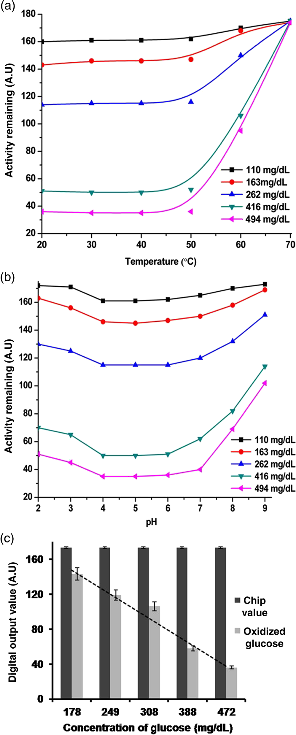 4.ConclusionsA number of studies have been reported for CMOS image sensor-based biological sensing. However, the current study has demonstrated whole blood glucose analysis using a CMOS image sensor via a new approach. Assay reagent immobilized nanoparticles were coated with a hydrophilic PET film chip and successfully applied to glucose oxidation. The CMOS image sensor measured the glucose level based on photon number variations. Characterization studies such as UV-spectral analysis, XRD, FTIR, and FE-SEM imagery have proven the accuracy of the sensing method. Moreover, CMOS image sensor-based glucose monitoring has been shown to be highly sensitive, specific, and stable for whole blood glucose sensing. Further study is underway on the CMOS image sensor-based analysis of human whole blood glucose to confirm the standard photon number for each glucose concentration with less blood. Finally, CMOS image sensor-based analysis of whole blood glucose can be successfully introduced into a smart phone for POC diagnosis. AcknowledgmentsThis work was supported by a grant of the Korea Health Technology R&D Project through the Korea Health Industry Development Institute (KHIDI) funded by the Ministry for Health and Welfare (HI15C0987 and HI14C1135) and the R&D Program for Society of the National Research Foundation (NRF) funded by the Ministry of Science, ICT & Future Planning (2015M3A9E2031372) of Korea. ReferencesR. Weiss and I. Lazar,
“The need for continuous blood glucose monitoring in the intensive care unit,”
J. Diabetes. Sci. Technol., 1 412
–414
(2007). Google Scholar
D. Nakayama et al.,
“Simple and precise preparation of a porous gel for a colorimetric glucose sensor by a templating technique,”
Angew. Chem., 115 4329
–4332
(2003). http://dx.doi.org/10.1002/ange.200351746 ANCEAD 0044-8249 Google Scholar
X. D. Wang et al.,
“Optical colorimetric sensor strip for direct readout glucose measurement,”
Biosens. Bioelectron., 24 3702
–3705
(2009). http://dx.doi.org/10.1016/j.bios.2009.05.018 BBIOE4 0956-5663 Google Scholar
Y. Xia et al.,
“Colorimetric visualization of glucose at the sub micromole level in serum by a homogenous silver nanoprism-glucose oxidase system,”
Anal Chem., 85 6241
–6247
(2013). http://dx.doi.org/10.1021/ac303591n ANCHAM 0003-2700 Google Scholar
S. V. Dzyadevych et al.,
“Amperometric enzyme biosensors: past, present and future,”
IRBM, 29 171
–180
(2008). http://dx.doi.org/10.1016/j.rbmret.2007.11.007 Google Scholar
B. H. Ginsberg,
“Factors affecting blood glucose monitoring: sources of errors in measurement,”
J. Diabetes Sci. Technol., 3 903
–913
(2009). http://dx.doi.org/10.1177/193229680900300438 Google Scholar
I. Heller et al.,
“STED nanoscopy combined with optical tweezers reveals protein dynamics on densely covered DNA,”
Nat. Methods, 10 910
–916
(2013). http://dx.doi.org/10.1038/nmeth.2599 1548-7091 Google Scholar
K. K. Ghosh et al.,
“Miniaturized integration of a fluorescence microscope,”
Nat. Methods, 8 871
–878
(2011). http://dx.doi.org/10.1038/nmeth.1694 1548-7091 Google Scholar
J. P. Devadhasan, S. Kim and J. An,
“FISH-on-a-chip: a sensitive detection microfluidic system for alzheimer’s disease,”
J. Biomed. Sci., 18 33
(2011). http://dx.doi.org/10.1186/1423-0127-18-33 Google Scholar
I. J. Su et al.,
“The emerging role of hepatitis B virus Pre-S2 deletion mutant proteins in HBV tumorigenesis,”
J. Biomed. Sci., 21 1
–8
(2014). http://dx.doi.org/10.1186/1423-0127-21-1 Google Scholar
J. P. Devadhasan et al.,
“A CMOS image sensor to recognize the cardiovascular disease markers troponin I and C-reactive protein,”
Anal. Bioanal Chem., 402 813
–821
(2012). http://dx.doi.org/10.1007/s00216-011-5478-1 ABCNBP 1618-2642 Google Scholar
J. P. Devadhasan and S. Kim,
“CMOS image sensor-based immunodetection by refractive-index change,”
Anal. Sci., 28 875
–880
(2012). http://dx.doi.org/10.2116/analsci.28.875 ANSCEN 0910-6340 Google Scholar
M. Marimuthu et al.,
“CMOS image sensor for detection of interferon gamma protein interaction as a point-of-care approach,”
Anal. Bioanal Chem., 401 1641
–1649
(2011). http://dx.doi.org/10.1007/s00216-011-5231-9 ABCNBP 1618-2642 Google Scholar
J. P. Devadhasan and S. Kim,
“Label free quantitative immunoassay for Hepatitis B,”
J. Nanosci. Nanotechnol., 15 85
–92
(2015). http://dx.doi.org/10.1166/jnn.2015.9253 JNNOAR 1533-4880 Google Scholar
F. A. Alrouq et al.,
“Study of the association of adrenomedullin and basic-fibroblast growth factors with the peripheral arterial blood flow and endothelial dysfunction biomarkers in type 2 diabetic patients with peripheral vascular insufficiency,”
J. Biomed. Sci., 21 94
(2014). http://dx.doi.org/10.1186/s12929-014-0094-y Google Scholar
A. J. Rosenbloom, H. R. Gandhi and G. L. Subrebost,
“Microdialysis coupled with an embedded systems controller and CMOS image sensor,”
Conf. Proc. IEEE Eng. Med. Biol. Soc., 2009 1230
–1233
(2009). http://dx.doi.org/10.1109/IEMBS.2009.5333471 Google Scholar
J. P. Devadhasan and S. Kim,
“Toward CMOS image sensor based glucose monitoring,”
Analyst, 137 3917
–3920
(2012). http://dx.doi.org/10.1039/c2an35458f ANLYAG 0365-4885 Google Scholar
J. P. Devadhasan, S. Kim and C. S. Choi,
“CMOS image sensors as an efficient platform for glucose monitoring,”
Analyst, 138 5679
–5684
(2013). http://dx.doi.org/10.1039/c3an00805c ANLYAG 0365-4885 Google Scholar
P. Y. Wang and M. S.-C. Lu,
“CMOS thermal sensor arrays for enzymatic glucose detection,”
IEEE Sens. J., 11 3469
–3475
(2011). http://dx.doi.org/10.1109/JSEN.2011.2161283 ISJEAZ 1530-437X Google Scholar
V. Oncescu, D. O. Dell and D. Erickson,
“Smartphone based health accessory for colorimetric detection of biomarkers in sweat and saliva,”
Lab Chip, 13 3232
–3238
(2013). http://dx.doi.org/10.1039/c3lc50431j LCAHAM 1473-0197 Google Scholar
B. Berg et al.,
“Cellphone based hand-held micro-plate reader for point-of-care testing of enzyme-linked immunosorbent assays,”
ACS Nano, 9 7857
–7866
(2015). http://dx.doi.org/10.1021/acsnano.5b03203 ANCAC3 1936-0851 Google Scholar
G. Comina, A. Suska and D. Filippini,
“Autonomous chemical sensing interface for universal cell phone readout,”
Angew. Chem. Int. Ed., 54 8708
–8712
(2015). http://dx.doi.org/10.1002/anie.201503727 Google Scholar
D. Zeng et al.,
“Gold nanoparticles-based nano conjugates for enhanced enzyme cascade and glucose sensing,”
Analyst, 137 4435
–4439
(2012). http://dx.doi.org/10.1039/c2an35900f ANLYAG 0365-4885 Google Scholar
R. P. Bagwe, X. Zhao and W. Tan,
“Bioconjugated luminescent nanoparticles for biological applications,”
J. Dispers. Sci. Technol., 24 453
–464
(2003). http://dx.doi.org/10.1081/DIS-120021801 JDTEDS 0193-2691 Google Scholar
R. E. Sabzi et al.,
“Electrocatalytic oxidation of dopamine at sol-gel carbon composite electrode chemically modified with copper hexacyanoferrate,”
J. Chin. Chem. Soc., 52 1079
–1084
(2005). http://dx.doi.org/10.1002/jccs.200500153 Google Scholar
G. Fu, X. Yue and Z. Dai,
“Glucose biosensor based on covalent immobilization of enzyme in sol-gel composite film combined with prussian blue/carbon nanotubes hybrid,”
Biosens. Bioelectron., 26 3973
–3976
(2011). http://dx.doi.org/10.1016/j.bios.2011.03.007 BBIOE4 0956-5663 Google Scholar
J. P. Devadhasan and S. Kim,
“Smart point-of-care systems for molecular diagnostics based on nanotechnology; whole blood glucose analysis,”
Proc. SPIE, 9523 952302
(2015). http://dx.doi.org/10.1117/12.2189576 PSISDG 0277-786X Google Scholar
V. N. Vasilets et al.,
“Microwave plasma-initiated vapour phase graft polymerization of acrylic acid onto polytetrafluoroethylene for immobilization of human thrombomodulin,”
Biomaterials, 18 1139
–1145
(1997). http://dx.doi.org/10.1016/S0142-9612(97)00045-8 BIMADU 0142-9612 Google Scholar
C. C. He and Z. Gu,
“Studies on acrylic acid-grafted polyester fabrics by electron beam preirradiation method. I. effects of process parameters on graft ration and characterization grafting products,”
J. Appl. Polym. Sci., 89 3931
–3938
(2003). http://dx.doi.org/10.1002/app.12646 JAPNAB 1097-4628 Google Scholar
Z. Zheng et al.,
“Surface modification on polyethylene terephthalate films with 2-methacryloyloxyethyl phosphorylcholine,”
Mater. Sci. Eng., 33 3041
–3046
(2013). http://dx.doi.org/10.1016/j.msec.2013.03.036 MSCEAA 0025-5416 Google Scholar
H. Yang and Q. Feng,
“Characterization of pore-expanded amino-functionalized mesoporous silicas directly synthesized with dimethyldecylamine and its application for decolorization of sulphonated azo dyes,”
J. Hazard. Mater., 180 106
–114
(2010). http://dx.doi.org/10.1016/j.jhazmat.2010.03.116 JHMAD9 0304-3894 Google Scholar
H. Yang and Q. Feng,
“Direct synthesis of pore-expanded amino-functionalized mesoporous silicas with dimethyldecylamine and the effect of expander dosage on their characterization and decolorization of sulphonated azo,”
Microporous Mesoporous Mater., 135 124
–130
(2010). http://dx.doi.org/10.1016/j.micromeso.2010.06.019 MIMMFJ 1387-1811 Google Scholar
J. Lin, J. A. Siddiqui and R. M. Ottenbrite,
“Surface modification of inorganic oxide particles with silane coupling agent and organic dyes,”
Polym. Adv. Technol., 12 285
–292
(2001). http://dx.doi.org/10.1002/pat.64 PADTE5 1099-1581 Google Scholar
A. M. Donia et al.,
“Effect of structural properties of acid dyes on their adsorption behavior from aqueous solutions by amine modified silica,”
J. Hazard. Mater., 161 1544
–1550
(2009). http://dx.doi.org/10.1016/j.jhazmat.2008.05.042 JHMAD9 0304-3894 Google Scholar
D. V. Quang et al.,
“Preparation of amino functionalized silica micro beads by dry method for supporting silver nanoparticles with antibacterial properties,”
Colloid. Surf. A, 389 118
–124
(2011). http://dx.doi.org/10.1016/j.colsurfa.2011.08.042 CPEAEH 0927-7757 Google Scholar
C. R. Martins et al.,
“Metal nanoparticles incorporation during the photopolymerization of polypyrrole,”
J. Mater Sci., 41 7413
–7418
(2006). http://dx.doi.org/10.1007/s10853-006-0795-z Google Scholar
J. Wang et al.,
“Synthesis of silica-coated ZnO nanocomposite: the resonance structure of polyvinyl pyrrolidone (PVP) as a coupling agent,”
Colloid. Polym. Sci., 288 1705
–1711
(2010). http://dx.doi.org/10.1007/s00396-010-2313-8 CPMSB6 0303-402X Google Scholar
BiographyJasmine Pramila Devadhasan received her PhD degree in biomedical engineering from Gachon University, South Korea in 2013. She is currently working as a postdoctoral fellow in the Department of Bionanotechnology, Gachon University, South Korea. She is doing her research in CMOS image sensor-based molecular diagnostics for various antigen-antibody interactions and whole blood glucose monitoring with point of care approach and smartphone-based real-time toxic chemical detection. In addition, she teaches advanced bionanosensor, biomedical engineering, and bioMEMS/NEMS. Hyunhee Oh received her MS and PhD degrees in nutritional biochemistry from Sungshin Women’s University of Food and Nutrition. She is currently working as a research associate in the Department of Molecular Medicine, Gachon University School of Medicine, South Korea. She has been studying the mechanism of development of obesity and diabetes as well as efficacy evaluation of metabolic disease therapeutics and diagnostic devices. Cheol Soo Choi received MD and PhD degrees in medicine from Pusan National University, South Korea. Currently, he is a professor of internal medicine and molecular medicine at Gachon University School of Medicine, South Korea. Over the past 20 years he has published over 100 articles on the pathogenesis of obesity and type 2 diabetes and his research interests include pathogenesis of obesity and diabetes, and discovery of therapeutic targets for obesity and diabetes. He is also interested in phenotyping genetically engineered mice associated with those diseases for investigating function of unknown genes. Sanghyo Kim received his MS and PhD degrees in chemical engineering from Pohang University of Science and Technology, South Korea. Currently, he is an associate professor in the Department of Bionanotechnology, Gachon University, South Korea. His research interests include biomaterials, tissue engineering, polymer engineering, molecular diagnostics, drug delivery and advance bioanalytical techniques. He has published more than hundred research papers, scientific reviews, and book chapters. |
|||||||||||||||||||||||||||||||||||||||||||||||||||||||||||||||


