
|
|
1.IntroductionBy mounting optical coherence tomography (OCT) devices on surgical microscopes, intraoperative continuous (or real-time), cross-sectional, high-resolution imaging becomes possible during ophthalmic surgery [intraoperative iOCT (iOCT)].1 In contrast to ultrasound biomicroscopy, tissue is visualized at tens of micrometer resolution without interrupting the procedure or contacting the eye with the imaging device.2,3 With iOCT, the relative depth distance of tissue structures and layers can be semiquantitatively assessed, even behind cloudy or scattering tissue areas.4 Hence, iOCT is an important additional imaging modality, which visualizes otherwise not visible structures inside the tissue, thereby aiding the surgeon in otherwise difficult situations and potentially increasing learning curves while reducing complication rates.5 At present, there are two iOCT systems commercially available, namely, the iOCT (Optomedical Technologies GmbH, Lübeck, Germany), mounted on the microscope HS Hi-R NEO 900A NIR (Haag Streit Surgical, Wedel, Germany); and the Rescan 700, mounted on the OPMI Lumera 700 (Carl Zeiss Meditec, Jena, Germany).6–8 However, the requirements of microscope-mounted iOCT devices are different from those used in a postoperative setup (Table 1).9 So far, OCT devices have to be integrated into surgical microscopes to fit into the operating theater and have to be controllable by the surgeon without interrupting or prolonging the surgical procedure. Prone and often-anesthetized patients are examined in this intraoperative setup. In addition, OCT imaging and interpretation are expanded to surgically manipulated eyes, and different tissues, materials, and variable structures. Despite these unsteady measuring conditions, an estimation of distances or, e.g., corneal pachymetry, is desirable (Table 1). Table 1Differences between office-based and iOCT.
We recently reported the potential benefit of iOCT during ab interno glaucoma surgery, canaloplasty, and Descemet’s membrane endothelial keratoplasty and deep anterior lamellar keratoplasty surgery.10–12 Moreover, we described iOCT as a useful tool for examinations of children with anterior segment anomalies.4 As an example for the application of iOCT in eye surgery, the treatment of recurrent graft failure with subsequent corneal opacification after penetrating keratoplasty is presented. Here, the implantation of a so-called keratoprosthesis (KPro) offers a viable alternative to further rekeratoplasty.13–15 The type I Boston KPro is the most widely implanted KPro. Large, multicenter studies report good long-term retention and visual acuity after implantation.16,17 Nonetheless, the surgical procedure of implanting the KPro is difficult, and correct intraoperative prosthesis assembly and accurate implantation are the key for satisfying visual results and reduced long-term complications.18 Recently, Qian et al.19 reported anterior segment OCT as useful imaging technique for the postoperative follow-up after KPro implantation, delivering important morphologic information, which was not accessible otherwise. However, at this stage, failure of the transplantation needs reoperation. In this context, we demonstrate for the first time the usefulness of iOCT during assembly and implantation of the Boston KPro type I, when correcting actions are easily possible. KPro imaging and evaluation by OCT are difficult in this respect, as the prosthesis consists of different materials [titanium, polymethylmethacrylate (PMMA), and corneal tissue]; assembly is performed out of the eye and implantation is performed within ocular tissues. We demonstrate that during the procedure, the intraoperative use of OCT delivers important information that is not visible with the normal surgical microscope. 2.Materials and Methods2.1.Surgical Procedure/Case ReportsRetrospective case series are presented of two patients (one 49-year-old male, one 92-year-old female) who underwent Boston type I KPro implantation at the Department of Ophthalmology, University of Cologne. KPro consists of a central PMMA optics, preventing central opacification of the optical axis, incorporated into a perforated titanium backplate. Intraoperatively, both parts were assembled and inserted into a donor cornea, which altogether replaces the previous opacified cornea of the patient. A snap-design, 8.5-mm backplate KPro was used. The underlying disease in both cases was graft failure after corneal transplantation (case 1: condition after one penetrating keratoplasty left eye; case 2: condition after two penetrating keratoplasties left eye). Assembly and implantation of the KPros were monitored, using iOCT [Figs. 1(a)–1(d)]. The Ethics Committee approved the retrospective analysis (Ethics Committee of the University of Cologne). All research was consistent with the Declaration of Helsinki. Fig. 1Components of the OCT system used in this study. (a) Microscope and OCT images are displayed simultaneously on the attached touch screen monitor (MIOS5 module with M.REC2, Haag Streit Surgical, Wedel Germany). (b) OCT images are displayed separately on a touch screen in the surgeons view (M.DIS, Haag Streit Surgical, Wedel, Germany). The iOCT is controllable by foot pedal and touch screen. (c) OCT camera head is connected to the camera port of the microscope. The OCT beam is lead via beam splitter (*) through the zoom optics (**) and the objective lens (***) of the microscope. (d) OCT images and scanning area are also displayed as overlay in the eye pieces of the microscope. Eye piece injection is toggled by the foot pedal. (e) Microscope and iOCT device are controllable by the surgeon using the foot pedal. 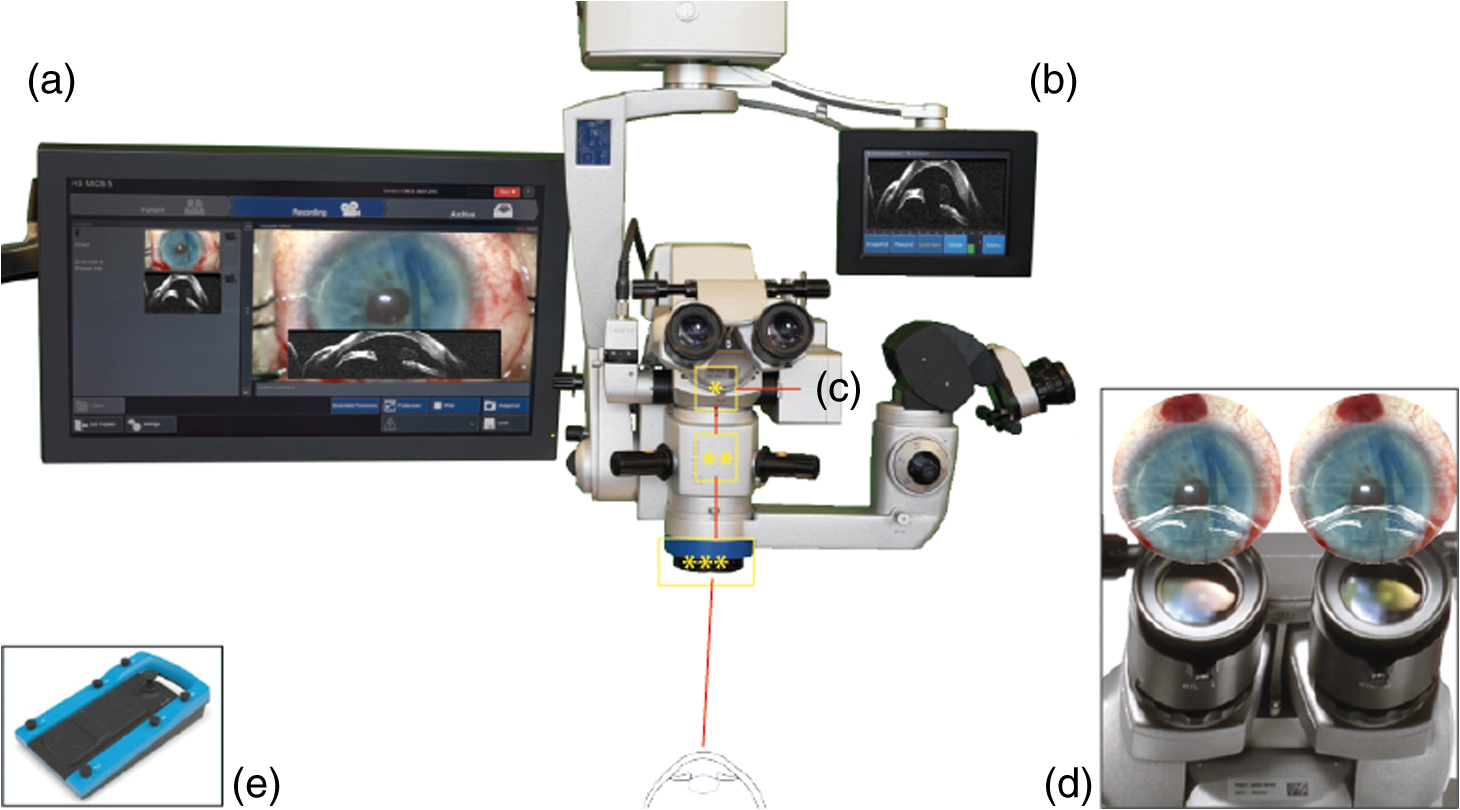 2.2.Technical DataTo enable iOCT, the spectral domain OCT-camera (iOCT, OptoMedical Technologies GmbH, Lübeck, Germany) was attached to the camera port of the surgical microscope (Hi-R Neo 900A NIR, Haag-Streit Surgical GmbH, Wedel, Germany) [Fig. 1(c)]. The OCT-camera head uses a two-axis scanner and a scanning optics, which are optimized for high performance at the camera port of the microscope. Using optical fiber and electric cable, the OCT-camera head is connected to the OCT base device, which consists of a broadband light-source and a spectral domain OCT detector with an axial resolution of about in air. The depth of the OCT window is 4.2 mm in air. With a speed of 10 pictures per second, the iOCT images are shown with 1000 A-scans each with 1024 pixels. The iOCT field of view changes with the continuously adjustable magnification of the microscope ranging between 5 and 30 mm. According to the magnification of the microscope, the lateral iOCT resolution changes between 11 (highest magnification) and (lowest magnification) (Fig. 2). Fig. 2Lateral iOCT scan width and corresponding lateral iOCT resolution (red scale) depending on the microscope magnification. The red dotted line indicates the aperture limit, which leads to the highest possible lateral iOCT resolution of a.u. (arbitrary units).  The iOCT images are displayed simultaneously with the microscope image on an extern touch-screen monitor (MIOS5 module with M.REC2, Haag Streit Surgical, Wedel Germany) and on a heads-up display (M.DIS, Haag Streit Surgical, Wedel, Germany) including a semiquantitative scale bar in the area of view of the surgeon at the microscope head [Figs. 1(a) and 1(b)]. Moreover, the OCT image and scan are superimposed within the eyepieces as transparent overlay for both eyes [Fig. 1(d)] and can be controlled and deactivated by the foot-switch [Fig. 1(e)]. The scan area is fixed horizontally in the middle of the visual field and not separately controllable or turnable. As the OCT beam in this system is led via a beam splitter through the zoom optics of the microscope and the objective lens, the focus of OCT and microscope is always at the same plane [Fig. 1(c)]. Therefore, the size of the scanned area is steeples adjustable by the zoom optics of the microscope (Fig. 2). Moreover, the focus is adjustable with regard to the examiner’s refraction and the area of interest during OCT imaging. All parts have been approved by the US Food and Drug Administration [510(K) Number: K 142953]. 2.3.Scanning SetupOCT imaging was performed online during the entire surgical procedure. No index matching gel was used. We scanned the whole area of interest manually using the “live-view” mode of the OCT device. If we found interesting structures, we added volume scans using the “quarter-scan” mode of the device. This function performs 30 B-scans and 1000 A-scans (ratio ). Scanning a volume takes about 2 to 3 s. 2.4.Evaluation Parameters and Data AnalysisSpecial attention was put at two time points during iOCT imaging, namely, assembling and following implantation of the prosthesis. Images were analyzed regarding visibility of correct assembly of all parts of the KPro and correct intraoperative implantation, especially in respect of anterior chamber depth and tilting of the optical unit of the prosthesis. For image analysis, free available image analyzing software (ImageJ) was used. 3.ResultsThe following two cases demonstrate the usefulness of iOCT during assembly and implantation of the Boston KPro type I. 3.1.Case 1A 49-year-old male patient suffering from graft failure after penetrating keratoplasty on the left eye, due to the condition after congenital cataract, lentectomy, aphakia, myopia, retinal detachment surgery, secondary glaucoma, cyclophotocoagulation, and band-keratopathy, underwent aphacic KPro implantation14 (axial length: 27 mm) under general anesthesia with reduced visual prognosis. Preoperative best-corrected visual acuity was finger-counting for the right eye (OD) and light perception for the left eye (OS). Boston KPro was performed as described earlier.14 Assembly and implantation of the KPro were monitored with the iOCT [Fig. 3(a)]. During assembly, a small gap between the anterior part of the optic and the graft became visible [Fig. 3(b)]. After reassembling and reattaching the backplate, iOCT demonstrated correct positioning of optic and graft [Fig. 3(c)]. Best postoperative visual outcome was hand movement. The patient developed a vitreous hemorrhage due to retinal detachment left 5 months later, and the visual outcome decreased to light perception after the vitreoretinal surgery. Fig. 3Case 1: a–d; case 2: F–H. (a) Microscope image during the assembling of the KPro (seen from posterior part during assembly), red line displays the OCT scanning area, (b) iOCT shows a dehiscence between the anterior (A) part of the optic and the corneal graft (C) (arrow), P, Posterior part of the optic. Posterior view of the prosthesis during assembling explains image orientation. Inset: A magnification of the dehiscence in detail. Parts of the anterior optics are invisible, due to shadowing by the titanium backplate. (c) iOCT demonstrates correct position of corneal graft and optics after reassembling the KPro. Anterior view of the already implanted prosthesis explains image orientation. (d) 3-D reconstruction of the implanted KPro; cornea (C), anterior (A), and posterior (P) part of the optics, titanium backplate (arrows), and contact lens (CL) are visible. (e) Microscope image during the assembling of the KPro (seen from anteriorly), red line displays the OCT scanning area. (f) iOCT shows a distance between the titanium backplate and the corneal graft (arrow). Inset: A magnification of the dehiscence in detail. View from anterior explains image orientation. (g) After implantation the distance is still visible with the iOCT (arrows). (h) Distance (arrows) is still visible during a postoperative control 2 weeks later (SL-OCT, Heidelberg Engineering, Heidelberg, Germany). Note that in (e)–(h) the contact between anterior optical part and anterior stroma is as tight as it should be.  3.2.Case 2A 92-year-old female patient suffering from graft failure after two penetrating keratoplasties on the left eye, due to condition after herpetic keratopathy, amniotic membrane transplantation, pseudophakia, age-related macular degeneration, secondary glaucoma, and Junius–Kuhnt´s syndrome, underwent standard KPro implantation under general anesthesia with reduced visual prognosis. Preoperative best-corrected visual acuity was finger-counting OD and hand-motion OS, and intraocular pressure was (iCare tonometer, iCare Oy, Finland). Pseudophacic Boston KPro implantation was performed as described earlier (Fig. 4). Assembly and implantation of the KPro were monitored with the iOCT [Fig. 3(e)]. The OCT device was able to visualize all parts of the prosthesis (donor graft, optic, and titanium backplate) [Fig. 3(f)]. During the examination with iOCT, a gap between the graft and the backplate became apparent [Figs. 3(f) and 3(g)]. As this space was not assumed to be the result of an incorrect prosthesis assembly and as it was not at the surface of the prosthesis and therefore could not increase the risk of postoperative infections, we decided against reassembling the KPro. This space did not change after implantation [Fig. 3(g)]. Two months after implantation, the space was still unaltered, and the best visual acuity was hand movement due to macular degeneration, and postoperative follow-up was without complications [Fig. 3(h)]. 4.DiscussioniOCT is a technique that combines high-resolution imaging with special requirements during delicate surgical procedures of the eye. The adaption of OCT to a surgical microscope enables the surgeon to visualize ocular structures during the intervention without the necessity for interruption. In contrast to office-based OCT devices, iOCT is operated under fundamentally different conditions. During surgery, the patient is in a horizontal position, often under general anesthesia, and unable to willingly position the eye. Also, instruments, injected air or fluids, artificial tissues, transplanted tissues, or materials are introduced in the field of view, thereby changing optical properties rapidly and blocking the en face field of view. This is a challenge for the surgeon and potential risk for the patient. iOCT provides cross-sectional two-dimensional and optional three-dimensional (3-D) images, thus adding valuable information to the surgeon in difficult optical or technical situations. Also, otherwise, only postoperative visible conditions such as attachment and alignment of lamellar corneal transplants may be acknowledged during surgery with the option of immediate correction and avoidance of postoperative complications. This first study on the use of iOCT during KPro surgery demonstrates the usefulness of iOCT during assembly and implantation of Boston KPro type I. iOCT was able to visualize all parts of the KPro during assembly and implantation. In addition, iOCT was superior in comparison to the surgical microscope in the visualization of unwanted “gaps” between the donor graft and the KPro backplate and the correct positioning of the optics in relationship to the corneal graft (Fig. 5). iOCT provides another level of safety when checking the correct assembly of the device prior to implantation. For example, here iOCT demonstrated two different types of intraoperative malposition during device assembly, which were not visible without iOCT and could be essential for the postoperative outcome. To our knowledge, these malpositions and their potential impact on graft and prosthesis survival, especially postoperative corneal melting and interface problems, are not known yet.14 Moreover, microscope-integrated OCT gives important information concerning the anatomical preoperative situation, especially in opacified corneas with reduced view of the anterior chamber or eyes with multiple previous ocular surgeries, anterior synechiae, or glaucoma implants (data not shown). Although these data are available via preoperative OCT or ultrasound biomicroscopy, iOCT is able to deliver online data during the surgical procedure itself. In addition, later, 3-D reconstruction and implant evaluation are possible [Fig. 2(d)]. As only few studies exist that provide information about important factors for the postoperative outcome after KPro implantation, we propose that future studies should also include intraoperative criteria visible on iOCT and examine them for their relevance on outcome after Boston Kpro. Fig. 5Schematic illustration of the KPro and the related dehiscences. Left: Dehiscence of the corneal graft (C) and the anterior (A) optics (O) of the prosthesis (arrow). Right: Dehiscence between the corneal graft and the posterior (P) titanium backplate (T) of the prosthesis (arrows).  Regarding the imaging features of the OCT device used in this study, all parts of the prosthesis despite being of varying materials, were visible and OCT imaging delivered important additional information. Nonetheless, shadowing of the titanium backplate limited imaging of the tissues behind [compare Figs. 2(b) and 2(f)]. iOCT enabled the surgeon nearly without interrupting the procedure to evaluate the surgical progress. In addition, a scale bar included to the monitor was helpful to estimate distances. To our knowledge, it is not feasible yet to include exact scale bars, because, as we demonstrate here, no standardized measuring environments exist or examined materials are strongly differing in their optical properties in the intraoperative setup. Intraoperative changes such as corneal hydration, intraocular pressure, or injected air or fluid interfere with measurements and focus alignment are additional challenges in software-based corrections of optical distortions. Nevertheless, this function would enable further precise surgical maneuvers, exact lamellar dissection of tissues, or placement of artificial materials such as intraocular lenses in the eye. During the imaging process, we evaluated the OCT images mostly using the screen. The eyepiece image injection was, despite its sufficient resolution, for our approach not superior to the 6.5″ screen, due to the decreased contrast of the visual field in relatively well-illuminated anterior segment surgery. Eyepiece injection could make sense especially during posterior segment surgery, but this was not evaluated in this study. Nonetheless, it has to be determined if eyepiece-integrated image injection really improves intraoperative imaging and if this technique does not interfere with the normal surgical field through the microscope. A benefit of the device we used was the controlling mechanism by foot-switch, so that further assistance was not necessary. In summary, online iOCT delivers additional information adding to the normal surgical microscope view during KPro surgery. Correct assembly can be controlled as well as the correct placement of Boston KPro into the anterior chamber. This technology will have a great impact on intraoperative use of surgical instruments, navigation within the eye, intraocular placement of artificial materials, and estimation of surgical success at the end of the procedure. Hereby, it is very likely that learning curves will be steepened and potential risks and complications will decline. AcknowledgmentsDFG FOR 2240 “(Lymph)Angiogenesis And Cellular Immunity In Inflammatory Diseases Of The Eye” (DH, PS, CC): www.for2240.de; EU COST BM 1302 “Joining Forces in Corneal Regeneration” (BB, CC, SS): www.biocornea.eu; Eva Lankenau is shareholder of OptoMedical Technologies GmbH, Lübeck, Germany. ReferencesE. M. Lankenau et al.,
“iOCT with surgical microscopes: a new imaging during microsurgery,”
Adv. Opt. Technol., 2
(3), 233
–239
(2013). http://dx.doi.org/10.1515/aot-2013-0011 Google Scholar
J. P. Ehlers, P. K. Kaiser and S. K. Srivastava,
“Intraoperative optical coherence tomography using the RESCAN 700: preliminary results from the DISCOVER study,”
Br. J. Ophthalmol., 98 1329
–1332
(2014). http://dx.doi.org/10.1136/bjophthalmol-2014-305294 BJOPAL 0007-1161 Google Scholar
Y. K. Tao et al.,
“Intraoperative spectral domain optical coherence tomography for vitreoretinal surgery,”
Opt. Lett., 35
(20), 3315
–3317
(2010). http://dx.doi.org/10.1364/OL.35.003315 OPLEDP 0146-9592 Google Scholar
S. Siebelmann et al.,
“Intraoperative optical coherence tomography in children with anterior segment anomalies,”
Ophthalmology, 122
(12), 2582
–2584
(2015). http://dx.doi.org/10.1016/j.ophtha.2015.06.004 OPANEW 0743-751X Google Scholar
J. P. Ehlers et al.,
“The prospective intraoperative and perioperative ophthalmic imaging with optical coherence tomography (PIONEER) study: 2-year results,”
Am. J. Ophthalmol., 158
(5), 999
–1007
(2014). http://dx.doi.org/10.1016/j.ajo.2014.07.034 AJOPAA 0002-9394 Google Scholar
J. P. Ehlers et al.,
“Integration of a spectral domain optical coherence tomography system into a surgical microscope for intraoperative imaging,”
Invest. Ophthalmol. Vis. Sci., 52
(6), 3153
(2011). http://dx.doi.org/10.1167/iovs.10-6720 Google Scholar
E. Lankenau et al.,
“Combining optical coherence tomography (OCT) with an operating microscope,”
Advances in Medical Engineering, 343
–348 Springer, Heidelberg Germany
(2007). Google Scholar
B. O. Bachmann et al.,
“A method to confirm correct orientation of Descemet membrane during Descemet membrane endothelial keratoplasty,”
Am. J. Ophthalmol., 149
(6), 922
–925
(2010). http://dx.doi.org/10.1016/j.ajo.2010.01.005 AJOPAA 0002-9394 Google Scholar
S. Siebelmann, P. Steven and C. Cursiefen,
“Intraoperative optical coherence tomography: ocular surgery on a higher level or just nice pictures?,”
JAMA Ophthalmol., 133
(10), 1133
–1134
(2015). http://dx.doi.org/10.1001/jamaophthalmol.2015.2396 Google Scholar
L. M. Heindl et al.,
“Future prospects: assessment of intraoperative optical coherence tomography in ab interno glaucoma surgery,”
Current Eye Res., 40
(12), 1288
–1291
(2014). http://dx.doi.org/10.3109/02713683.2014.995311 CEYRDM 0271-3683 Google Scholar
P. Steven et al.,
“Optimizing Descemet membrane endothelial keratoplasty using intraoperative optical coherence tomography,”
JAMA Ophthalmol., 131
(9), 1135
–1142
(2013). http://dx.doi.org/10.1001/jamaophthalmol.2013.4672 Google Scholar
P. Steven et al.,
“Optimising deep anterior lamellar keratoplasty (DALK) using intraoperative online optical coherence tomography (iOCT),”
Br. J. Ophthalmol., 98
(7), 900
–904
(2014). http://dx.doi.org/10.1136/bjophthalmol-2013-304585 Google Scholar
V. S. Avadhanam and C. S. Liu,
“A brief review of Boston type-1 and osteo-odonto keratoprostheses,”
Br. J. Ophthalmol.,
(2014). http://dx.doi.org/10.1136/bjophthalmol-2014-305359 BJOPAL 0007-1161 Google Scholar
W. B. Lee et al.,
“Boston keratoprosthesis: outcomes and complications: a report by the American academy of ophthalmology,”
Ophthalmology, 122
(7), 1504
–1511
(2015). http://dx.doi.org/10.1016/j.ophtha.2015.03.025 OPANEW 0743-751X Google Scholar
N. Schrage, K. Hille and C. Cursiefen,
“Current treatment options with artificial corneas: Boston Kpro, Osteo-odontokeratoprosthesis, Miro Cornea® and KeraKlear®,”
Ophthalmologe, 111
(11), 1010
–1018
(2014). http://dx.doi.org/10.1007/s00347-013-3009-5 Google Scholar
J. B. Ciolino et al.,
“Retention of the Boston keratoprosthesis type 1: multicenter study results,”
Ophthalmology, 120
(6), 1195
–1200
(2013). http://dx.doi.org/10.1016/j.ophtha.2012.11.025 OPANEW 0743-751X Google Scholar
B. L. Zerbe et al.,
“Results from the multicenter Boston type 1 keratoprosthesis study,”
Ophthalmology, 113
(10), 1779
–1784
(2006). http://dx.doi.org/10.1016/j.ophtha.2006.05.015 OPANEW 0743-751X Google Scholar
D. Srikumaran et al.,
“Long-term outcomes of Boston type 1 keratoprosthesis implantation: a retrospective multicenter cohort,”
Ophthalmology, 121
(11), 2159
–2164
(2014). http://dx.doi.org/10.1016/j.ophtha.2014.05.030 OPANEW 0743-751X Google Scholar
C. X. Qian, S. Hassanaly and M. Harissi-Dagher,
“Anterior segment optical coherence tomography in the long-term follow-up and detection of glaucoma in Boston type I keratoprosthesis,”
Ophthalmology, 122
(2), 317
–325
(2014). http://dx.doi.org/10.1016/j.ophtha.2014.08.007 OPANEW 0743-751X Google Scholar
|


