|
|
1.IntroductionWhite-light imaging and human vision lack the ability to visualize under the tissue surface and are not sensitive to pathophysiological and molecular differences between diseased and healthy tissue, occasionally limiting the accurate estimation of tumor extent and tumor margins. Interventional fluorescence imaging may address these limitations in surgical or endoscopic surveillance and guidance and improve intraoperative cancer detection. Features such as high sensitivity, real-time imaging, and subsurface signal detection make interventional fluorescent molecular imaging an attractive modality for surgical guidance. There are three general mechanisms for generating contrast for fluorescence imaging: the first uses nonspecific fluorescence dyes that are distributed in the vascular system; the second uses fluorescent agents that target specific moieties associated with disease, and the third is based on visualizing intrinsic or induced autofluorescence.1 One of the most widely used nonspecific fluorescent agents is indocyanine green (ICG), which was FDA approved in 1959 and has been extensively used in various clinical applications including surgery or endoscopy.1,2 ICG distributes primarily in the vascular system and may preferentially perfuse tumors through the enhanced permeability and retention (EPR) effect but it has not been so far shown efficient for tumor delineation and margin detection. Another dye used in intraoperative applications is methylene blue, which is primarily employed for sentinel lymph node identification and mapping.3,4 Lymph node mapping has also been successfully achieved by ICG.5–7 Fluorescent agents that target specific cellular or molecular disease moieties are increasingly considered for improving intraoperative disease detection over ICG. Folate (B-vitamin) conjugated to fluorescein isothiocyanate (Folate-FITC) has been used to detect cancer foci in ovarian cancer patients and yielded five times more accurate visualization over stand-alone color images.8 Similar agents have outlined renal cell carcinoma during surgery9 and are considered in breast cancer detection.10 An FITC-labeled peptide that binds specifically to high-grade dysplasia and adenocarcinoma has been developed and used successfully for esophageal neoplasia visualization.11 Furthermore, FITC-labeled adalimumab was used for visualization of mTNF+ cells and correlated their number to the short-term Crohn’s disease response rates.12 There is a much larger pool of potent agents, including labeled drugs that are considered for intraoperative imaging.1,13 The use of 5-ALA (aminolevulinic acid) to induce cancer autofluorescence also has been considered for intraoperative imaging applications. Glioma cells convert 5-ALA to protoporphyrin IX (PPIX), which emits an intense red fluorescence signal under blue illumination. The approach has been employed in fluorescence guided resection of malignant gliomas or benign tumors such as ependymomas or meningiomas in adults14,15 and children.16,17 A large number of fluorescent camera implementations have been developed to capture fluorescence images from tissue during surgery or endoscopy.6,18–20 A common example uses a color and a fluorescence camera, visualizing the same field of view, so that color and fluorescence images can be registered. Hybrid color-fluorescence cameras combine morphological (white-light) views and the underlying fluorescence contrast onto one image. Single camera systems visualizing only fluorescence have also been considered for reducing cost and camera weight.21 Alternative approaches build systems with multiple cameras to visualize at different spectral bands. For example, three camera systems have been employed to collect images from two different NIR channels and one visible channel5,22 or for collecting information at different spectral regions for correcting fluorescence images for illumination and tissue-absorption variations in real time.23,24 Endoscopic and laparoscopic systems have also been developed and successfully applied in minimally invasive cancer therapy.20,25 Several fluorescence imaging systems are currently commercialized for intraoperative and endoscopic use. The wide range of intraoperative system technologies today comes with the fundamental requirement to benchmark different systems and better understand fluorescence imaging performance. For this reason, fluorescence phantoms have been proposed for system calibration. These phantoms typically mimic the optical properties of human or animal tissue at select spectral windows and contain known contrast, which is employed to characterize the camera performance. In the following, we review common fluorescence phantoms and then propose a phantom design strategy that combines multiple targets at a single block, aiming to offer a comprehensive method for fluorescence imaging evaluation. 2.Fluorescence PhantomsThe development of optically diffusive phantoms that mimic the optical properties of living tissue and the biodistribution of fluorochromes in tissues has been considered for investigating light–tissue interaction phenomena and for assessing different imaging systems.26 Generally, the phantoms developed should meet two basic requirements. They need to provide: (i) long-term photostability in diverse environmental conditions and (ii) a fixed shape (termed solid phantom) that allows no mechanical deformation over time. To meet these requirements, phantoms typically use epoxy, polyester resin, or polyurethane as base material, which can be cured and machined to different shapes and volumes and quantum dots (QDots) for fluorescence emission. Unlike organic fluorophores that suffer from fast photobleaching, QDots provide better photostability, required in applications involving long-term imaging.27–29 2.1.Phantoms Simulating Tissue Optical PropertiesSeveral photon propagation parameters and system specifications can be examined using phantoms. A polyurethane-based phantom has been suggested to assess the sensitivity of fluorescence cameras.30 The phantom comprised six cylindrical wells that contained particles to impart photon scattering and varying quantities of NIR fluorescent QDots dispersed in polyurethane [Fig. 1(a)]. The camera sensitivity was then assessed from an image of the phantom by observing the number of visible wells on the image. In addition, epoxy–resin-based phantoms that combine titanium dioxide () and aluminum oxide () can be employed to control for photon scattering anisotropy and the phase function.31 Fig. 1(a) Phantom of fluorescent wells of different strength employed to assess the sensitivity of far-red and near-infrared fluorescence imaging systems. Adapted from Ref. 30 with permission. (b) Cylindrical phantom constructed to assess fluorescent capillaries immersed at different depths under the surface within a medium simulating tissue optical properties (cross-sectional view) reproduced from Ref. 33 with permission. (c) Schematics of a bilayer (up) and an inclusion (down) phantom. Adapted from Ref. 34 with permission. 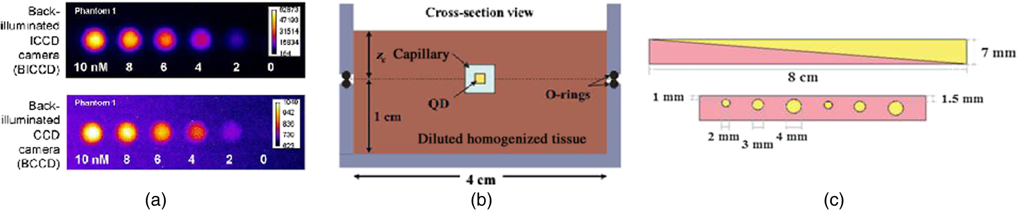 A different phantom, made by spraying a polyurethane–QDot solution onto a reflective surface, has been suggested for determining the leakage of excitation light into the fluorescence channel of a camera.32 Images from the QDot distribution containing both fluorescence and light-leakage signals are compared to images from an area that does not contain QDots to separate the strength of fluorescence contributions compared to excitation light cross talk into the fluorescence channel. Zhu et al. further suggest the use of varying QDots solutions to infer the dynamic range of the camera. In another study,33 a customized cylindrical structure with fully submerged thin tubes containing a solution of (CdSe)ZnS QDots in chloroform was constructed for assessing the imaging quality achieved as a function of fluorochrome depth. The medium surrounding the tubes consisted of a water-based homogeneous solution containing intralipid-20%, naphthol green B powder, and distilled water. A small amount of AlexaFluor 568 (0.2 mg in a total volume of 320 mL) was added to simulate tissue autofluorescence [Fig. 1(b)]. The use of phantoms that establish a geometry with varying thickness and optical properties Fig. 1(c)] was suggested for characterizing tissue autofluorescence and validating fluorescence tissue analysis.34 The phantoms were made of porcine skin gelatin and employed rhodamine B (RhB) or FITC to impart fluorescence. The optical properties were selected to correspond to normal and diseased brain tissues. Rectangular phantoms containing variable-diameter cylindrical inclusions placed in parallel were also suggested.34 2.2.Shape-Maintaining and Organ-Mimicking Fluorescent PhantomsA different class of tissue-mimicking phantoms focuses on simulating the geometrical features of tissue organs and can be used for clinical training in intraoperative imaging. A lymph-node mimicking phantom was constructed21 to assess the efficacy of a real-time fluorescence imaging system [Fig. 2(a)]. The phantom was made of thin-walled polyoxymethylene cones (15-mm long and thick) filled with scattering fluid (water and whole ultraheat treated milk of 3.5% fat) and fluorescent dye (ICG-Pulsion). Five lymph node-mimicking cones were mounted on a holder and immersed in a glass reservoir containing a water and milk scattering fluid. Fig. 2(a) Fluorescence lymph node phantom: cross-sectional view, reflectance image, and normalized epi-fluorescence image. Adapted from Ref. 21 with permission. (b) Complex phantom containing four compartments (a–d) with different optical properties, each of them contains a fluorescent 1-mm bead (indicated by arrow) that is detected using NIRF reproduced from Ref. 35 with permission. (c) Preoperative detection of fluorescent tumor-simulating inclusion using NIRF; figure reproduced from Ref. 36 with permission. 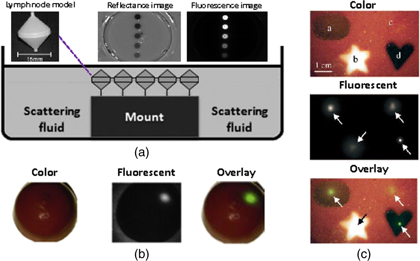 Rectangular- or breast-shaped phantoms were also considered as a tool to train surgeons in intraoperative fluorescence imaging in breast cancer.35,36 A phantom made of Tris-buffered saline (TBS, buffer), sodium azide, gelatin, and varying amounts of intralipid and haemoglobin was employed to simulate the geometry, optical properties, and the mechanical properties of the human breast.35 ICG-tagged polystyrene divinylbenzene beads (AG1-X8) or Pam78-labeled hydroxyapatite crystals (simulating breast cancer microcalcifications) were used as fluorophore inclusions [Fig. 2(b)]. In Ref. 36, varying-shaped ICG-agarose inclusions were embedded in a mixture of TBS, gelatin, , haemoglobin, and Intralipid©, and the final structure was visualized using a customized NIRF system optimized for real-time surgical imaging36 [Fig. 2(c)]. 2.3.Requirement for a New Class of PhantomsTable 1 summarizes a nonexhaustive list of fluorescent phantoms and demonstrates a great variability in approaches and materials used. The phantoms listed have been developed to address different specifications and needs, e.g., the characterization of a specific property (e.g., sensitivity) or the study of a physical property (e.g., effect of depth). Typically, only a single or few specifications are addressed.30,32,37 However, there is a large range of parameters that may require validation in the clinical use of fluorescence cameras. Parameters such as the illumination homogeneity, the resolution, the dependency of fluorescence intensity on tissue optical properties, or depth are not generally comprehensively addressed in the phantoms built so far. Therefore, there is a need for a new class of phantoms that simultaneously assess multiple parameters. This is particularly a requirement in intraoperative settings, where a single image calibration can longitudinally confirm system operation. Also, a comprehensive phantom that concurrently enables the measurement of multiple camera parameters is necessary for the comparison of different camera systems or operational parameters. The use of a comprehensive phantom, therefore, eliminates the need to develop a large number of different phantoms, each testing a single or few parameters only. Table 1Examples of fluorescent phantoms found in the literature (nonexhaustive list).
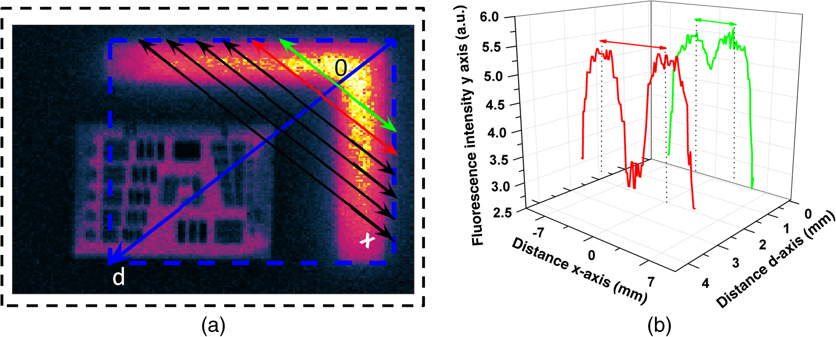
3.MethodsWe designed and constructed a solid polyurethane phantom with the purpose of evaluating a range of camera parameters using a single snapshot. The parameters assessed include sensitivity, fluorescence intensity variations as a function of optical properties and depth, cross talk from excitation light leaking into the fluorescence channel, illumination homogeneity, and resolution. 3.1.Phantom Design and FabricationThe solid phantom designed is depicted in Fig. 3. Figure 3(a) shows a color image of the fabricated phantom and Fig. 3(b) shows a fluorescence image of the phantom. The phantom is made of transparent rigid polyurethane (WC-783 A/B, BJB Enterprises, Tustin) and contains different structures interrogating different aspects of fluorescence camera specifications and imaging performance. The outer dimensions of the phantom are . The background absorption was set to at 750 nm, using alcohol soluble nigrosin (Sigma Aldrich, St. Louis). Scattering was imparted by using particles (Titanium IV Oxide, Sigma Aldrich, St. Louis), resulting in a reduced scattering coefficient of at 750 nm. The high-background absorption coefficient in this phantom offers the additional advantage of low photon diffusion from the different structures selected into the background medium. The absorption coefficient was determined by measuring the extinction coefficient of nigrosin using an Ocean Optics USB4000-UV-VIS spectrometer and then selecting the appropriate concentration to impart the desired absorption coefficient. The reduced scattering coefficient was determined by fitting the diffusion equation in a measurement of the spatial transmittance profile of a point source through a 1-cm slab of cured polyurethane containing particles and a known absorption coefficient, as determined by measuring the solvent by photospectrometry prior to the addition of the particles. All the inlets in the phantom, except for the ones used for depth dependence evaluation, were made 12-mm deep. The different phantom compartments are schematically explained in Fig. 3(c). Fig. 3Top view of the phantom. (a) Color image of the phantom. (b) Fluorescence image (765 to 855 nm) of the phantom excited at 750 nm. (c) Schematic of the phantom. 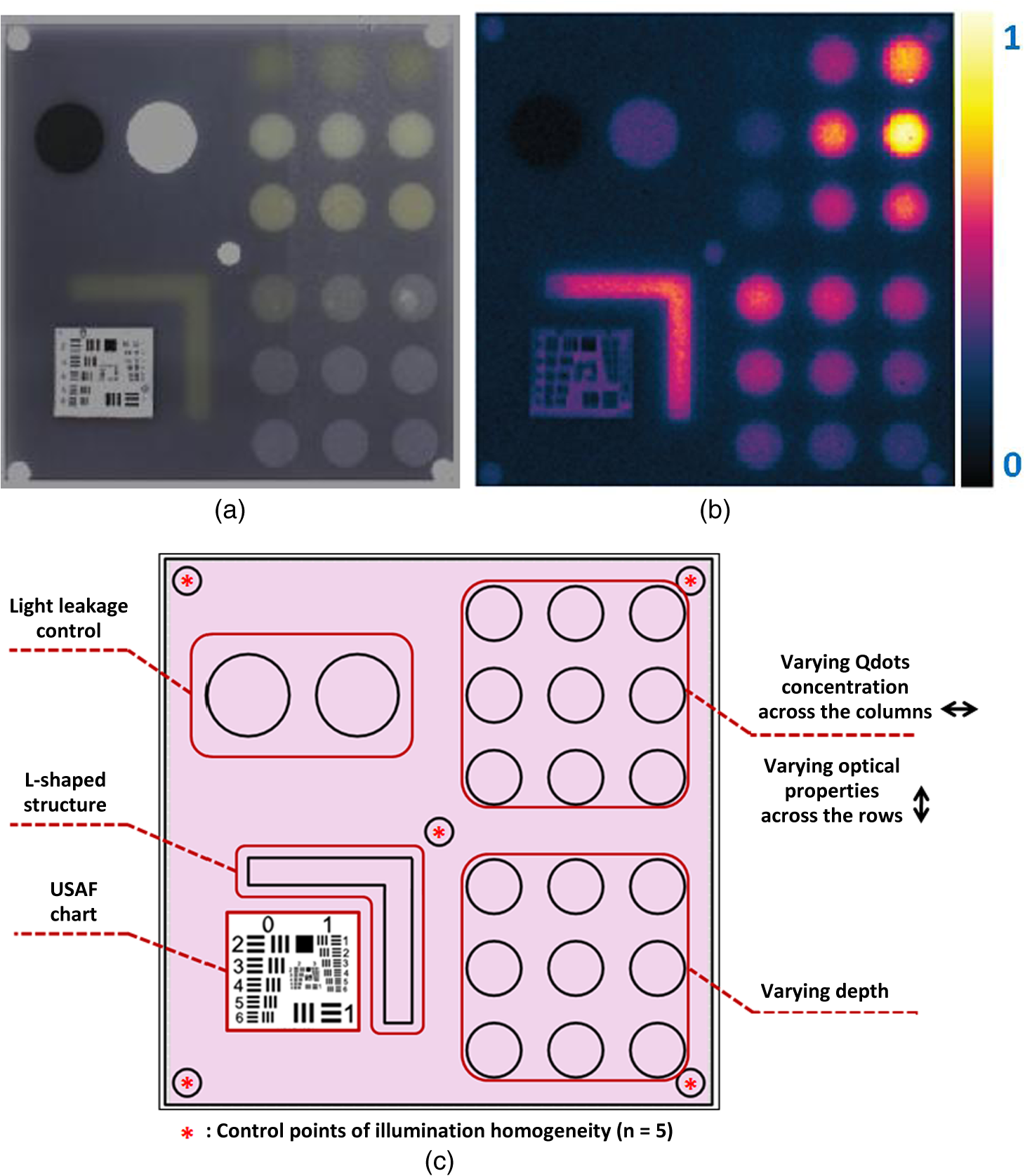 The upper-right quadrant of the phantom interrogates the sensitivity and fluorescence intensity variation as a function of optical properties through an array of nine fluorescent wells (10-mm diameter). The wells contain a mix of cured polyurethane with QDots (800-nm emission; Thermofisher Scientific, Waltham) at varying concentrations (1, 5, and 10 nM) across the columns and varying absorber (20, 20, and Hemin) and varying amounts (0.33, 0.66, and ) across the rows. Hemin (Sigma Aldrich, St. Louis) was selected to simulate an absorption coefficient for and for . The bottom-right quadrant comprises nine fluorescence wells; whereby 10-mm diameter cylinders made of 10 nM 800 nm QDots particles and Hemin were embedded at varying depths within the phantom, i.e., at an increasing depth from the phantom surface at 0.2, 0.4, 0.6, 0.8, 1, 1.33, 1.66, 2, and 3 mm. After the QDot mix was poured into the well to reach the appropriate depth, it was allowed to cure and then the cavity was filled with the same material employed in the construction of the phantom body. This quadrant examines the fluorescence sensitivity to depth and can be used to study the ability of a system or method to account for the effects of depth on the fluorescence signal. The upper-left quadrant examines the camera dark-current offset and the camera cross talk, i.e., the excitation light leakage into the fluorescence channel. Light leakage could be caused due to inadequate excitation light rejection from system filters. This area comprises a circular well of very high absorption coefficient ( nigrosin) and one of low absorption and high scattering coefficient ( titanium oxide) offering reflecting characteristics. The circular elements were embedded in the background material and do not contain fluorescence substances. Inspection of the dark area approximates the dark-light camera photon count “dc-offset” (although a separate measurement with the excitation light off also can be performed). Inspection of the reflective nonfluorescent area reveals the camera cross talk with better signal-to-noise ratio characteristics over observing the cross talk seen from the phantom background material. This cross talk measurement can be utilized in different ways as discussed in Sec. 3.2. In addition, signals captured in the fluorescence channel from the highly scattering well of the upper-left quadrant can be employed in a differential way to evaluate stray light, e.g., using two measurements, one with ambient light on and one with ambient light off. Finally, the lower-left quadrant tests for the resolution of the optical system and cameras employed. A standard 1951 United States Air Force resolution test chart is fixed on the top of the phantom to interrogate the white-light optical resolution, useful for characterizing the color or the fluorescence camera employed. In addition, an L-shaped diffusive fluorescence structure, made of polyurethane, particles, Hemin, and 10 nM QDots, was embedded for the examination of photon diffusion and fluorescence resolution. The outer dimensions of the L-shaped structure are , whereas the width of each branch is 5 mm. There are five identical reflective circular areas (5-mm diameter) made of titanium oxide in polyurethane, four at the corners of the phantom and at the center sample the homogeneity of the light illumination employed by the camera system. The phantom was produced by molding a cuboid made of the base material. After curing, the cuboid was treated by face milling of the surfaces. Openings were milled for each of the desired wells and shapes. All milling procedures were performed on a cartesian computer numerical controlled three-axis milling router with resolution. 3.2.Imaging SystemA home-made EagleRay-V3 imaging system previously developed for intraoperative imaging38 was employed for the experimental measurements herein. The EagleRay-V3 system is a hybrid color-fluorescence system employing an iXon-3 electron multiplying charge-coupled device (DU-897 EMCCD; Andor Technology, Belfast, Ireland) for fluorescence detection and a 12-bit-CCD camera (pixelfly qe, PCO, Kelheim, Germany) for color detection. A 300-mW continuous laser diode (BWF2-750-0, B&W Tek, Newark) at 750 nm was used for fluorescence excitation and a 250-W halogen lamp (KL-2500 LCD, Scott, Mainz, Germany) was employed for white-light illumination. 4.ResultsWe demonstrate the analysis of phantom images and suggest possible uses of the analysis in characterizing system parameters. These parameters can be employed to compare different systems to each other, using a single photographic measurement for each system. Another use of the parameters extracted from phantom measurements is to confirm that the system performs identically from day to day, a parameter that is particularly critical in intraoperative environments. 4.1.Sensitivity and Intensity Variation Due to Optical PropertiesSystem sensitivity can be assessed by observing the fluorescence collected from the upper-right quadrant wells. Figure 4(b) shows the fluorescence profiles across the nine wells, plotted from right to left as shown in Fig. 4(a). The profiles demonstrate variations in intensity since each row of the matrix of cells contains a different combination of optical properties and each column contains a different QDot concentration at 1, 5, and 10 nM from right to left, respectively. The plot allows the evaluation of sensitivity not only under different fluorochrome concentrations, but also for varying optical properties. Even though each column contains exactly the same amount of QDots, different fluorescence intensities are recorded from the three wells in that column due to the variation of optical properties. Importantly, therefore, the upper-right quadrant can also be employed to evaluate algorithms that account for the effects of optical properties on the fluorescence intensity. Fig. 4Cross sections of the fluorescent image of the phantom. (a) Phantom schematic with arrows painted with colors corresponding to the cross sections. (b) Fluorescence intensity across each column (different fluorophore concentration). (c) Intensity across the highly reflecting and absorbing area. (d) Fluorescence intensity for different depths. (e) Fluorescence intensity versus the depth distance. 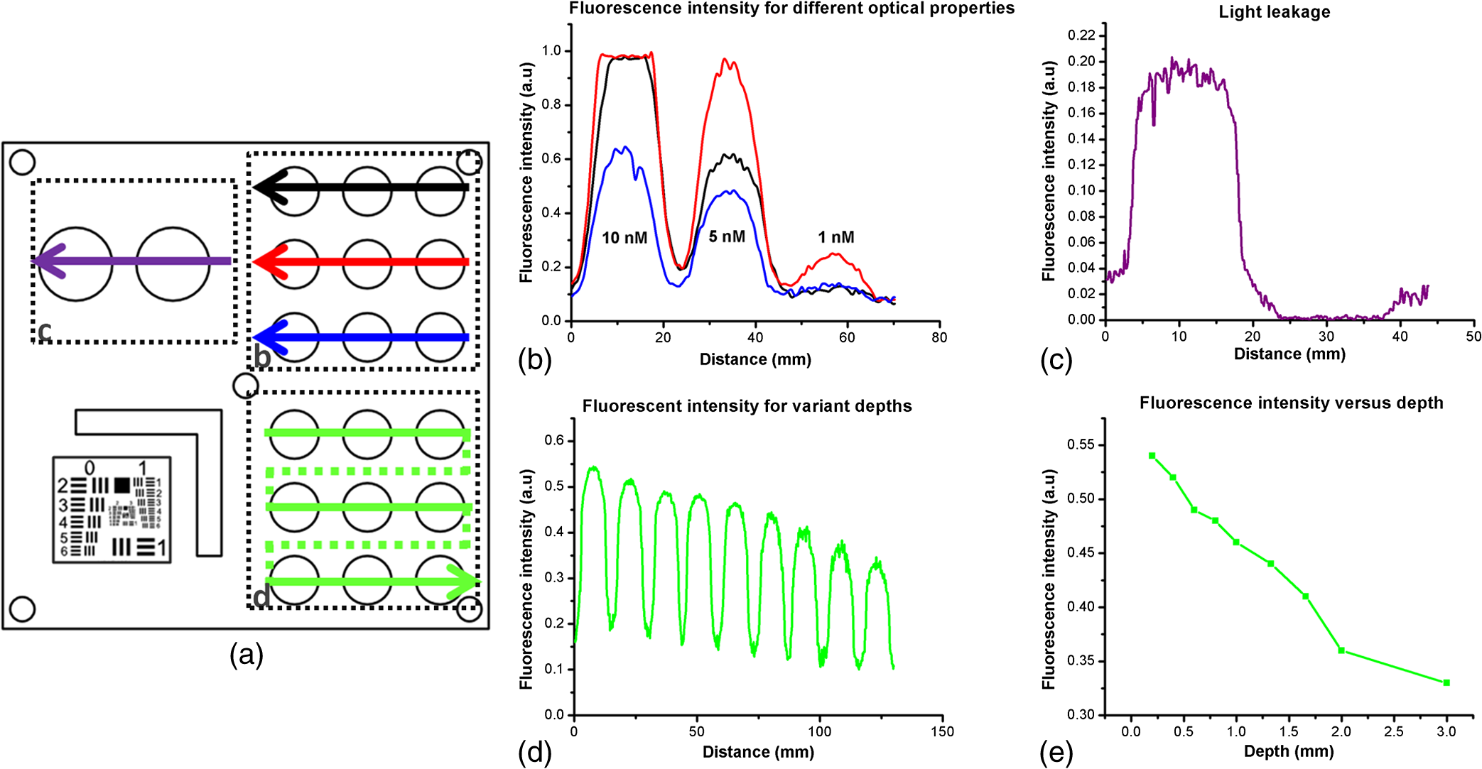 As observed in Fig. 4(d), the system can detect 1 nM of fluorochrome concentration only in the low-attenuation well. Therefore, it appears that under the operational conditions applied herein, the sensitivity of the system is between 1 and 5 nM, depending on the background optical properties. 4.2.Light LeakageFigure 4(c) depicts the cross section across the two wells contained in the upper-left quadrant of the phantom, which examines the light leakage and dark count. The light-leakage measurement can be utilized in different ways. It can be related to fluorescence intensity measurements (e.g., from the upper-right quadrant of the phantom) to provide a relative metric of light-leakage recorded from a low-absorption and nonfluorescent lesion to measurements from lesions containing varying amounts of fluorochrome. The ratio of fluorescence measurement for a certain well in the upper-right quadrant over the light-leakage signal is a quality metric; the higher the value the better the ability of a camera to discriminate a fluorochrome over cross talk. Another method utilizing the light-leakage measurement is to observe the intensity of the excitation light reflected off the reflective well using the color camera [i.e., from Fig. 3(a)] and generate a ratio of the light-leakage measurement [from Fig. 3(b)] over reflected light in Fig. 3(a). This ratiometric measure can also be used to compare the performance of different cameras or examine the performance of algorithms correcting for light leakage. The measurement shown in Fig. 4(c) was intentionally performed using filters offering medium excitation light rejection to illustrate that it is possible to obtain light-leakage signals that are stronger than fluorescence signals, depending on the system design. For example, when comparing the signal intensity collected in the leakage channel to the fluorescence intensity seen in the left-most column of the upper-right quadrant, one can observe that the light leakage is stronger than the fluorescence signal obtained from low (1 nM) QDot concentrations and highly absorbing lesions. 4.3.DepthFigure 4(d) shows the fluorescence intensity profiles as a function of fluorochrome depth across the nine varying depth entities, plotted in the order that is indicated by the arrow in Fig. 4(a). As expected, a decrease of fluorescence intensity is observed for increasing depth. The rate of signal drop with depth is depicted in Fig. 4(e). This figure shows at least a twofold fluorescence intensity reduction over the first 3 mm of lesion depth and for the optical properties selected. This measurement can be employed to examine the performance of cameras and algorithms that account for depth-related fluorescence signal variations. 4.4.Fluorescence ResolutionFigure 5 shows the fluorescence image from the lower-left quadrant, which can be employed to evaluate the diffusive resolution achieved in the fluorescence channel. The manufactured L-shape has a sharp border. However, due to photon diffusion, the border appears of low resolution. To evaluate the diffusive resolution, we plotted fluorescence intensity profiles [Fig. 5(b)] along the diagonal double-arrow lines plotted in Fig. 5(a). The diagonal double-arrow line indicates the -axis in Fig. 5(b), whereas the -axis is the fluorescence intensity recorded along the profile shown and the position on the -axis indicates the distance from the inner vertex of the L-shaped structure. The minimum step between the lines could be 1 pixel diagonal, but for better visualization, a step of 20 diagonal lines was used. The profiles confirm that even though the L-shape has been constructed with a hard border between fluorescence and nonfluorescence material, the resulting reading has a diffusive appearance. These readings can be useful for evaluating cameras and algorithms that improve upon photon diffusion. One resolution improvement metric that could be implemented with this phantom would be the comparison achieved between the L-shaped edge (border) resolved on a diffusion-corrected image and the location of the known manufactured edge of the L-shaped structure. Another resolution metric could be implemented by reporting the distance on the -axis [Fig. 5(b)], whereas the plotted fluorescence intensity profiles start to be resolved. The L-shaped phantom allows for a gradual distance increase between the two edges, so that different distances between the edges can be seamlessly evaluated. 4.5.Illumination HomogeneityThe illumination homogeneity can be evaluated by plotting the intensity measurements recorded for the five reflective wells placed in the corners and center of the phantom. Figures 6(a) and 6(b) depict the intensity profiles as cross sections across the five reflective wells. These profiles serve as a quick estimation of the illumination field homogeneity. Using five sampling points, we can define a three-dimensional surface that approximates the illuminating field. Since a single illumination source was employed in this study, we fitted a cubic spline curve to the five points, as shown in Fig. 6(c). More generally, a larger number of sampling points on the phantom and higher order polynomial surface fits can be employed for describing more complex illumination fields. Tracking the illumination pattern, as shown in Fig. 6(c), can help in correcting the fluorescence images by normalizing them for the excitation field variation or help to adjust the illumination to make it more homogeneous. Fig. 6Assessment of the homogeneity of the illumination field of the camera system. (a) Homogeneity profiles across the left-upper-corner to right-bottom-corner. (b) Homogeneity profiles across the right-upper-corner to left-bottom corner. (c) Comparison of the five reflective spots surface profile with the surface profile of a white reflectance sheet. 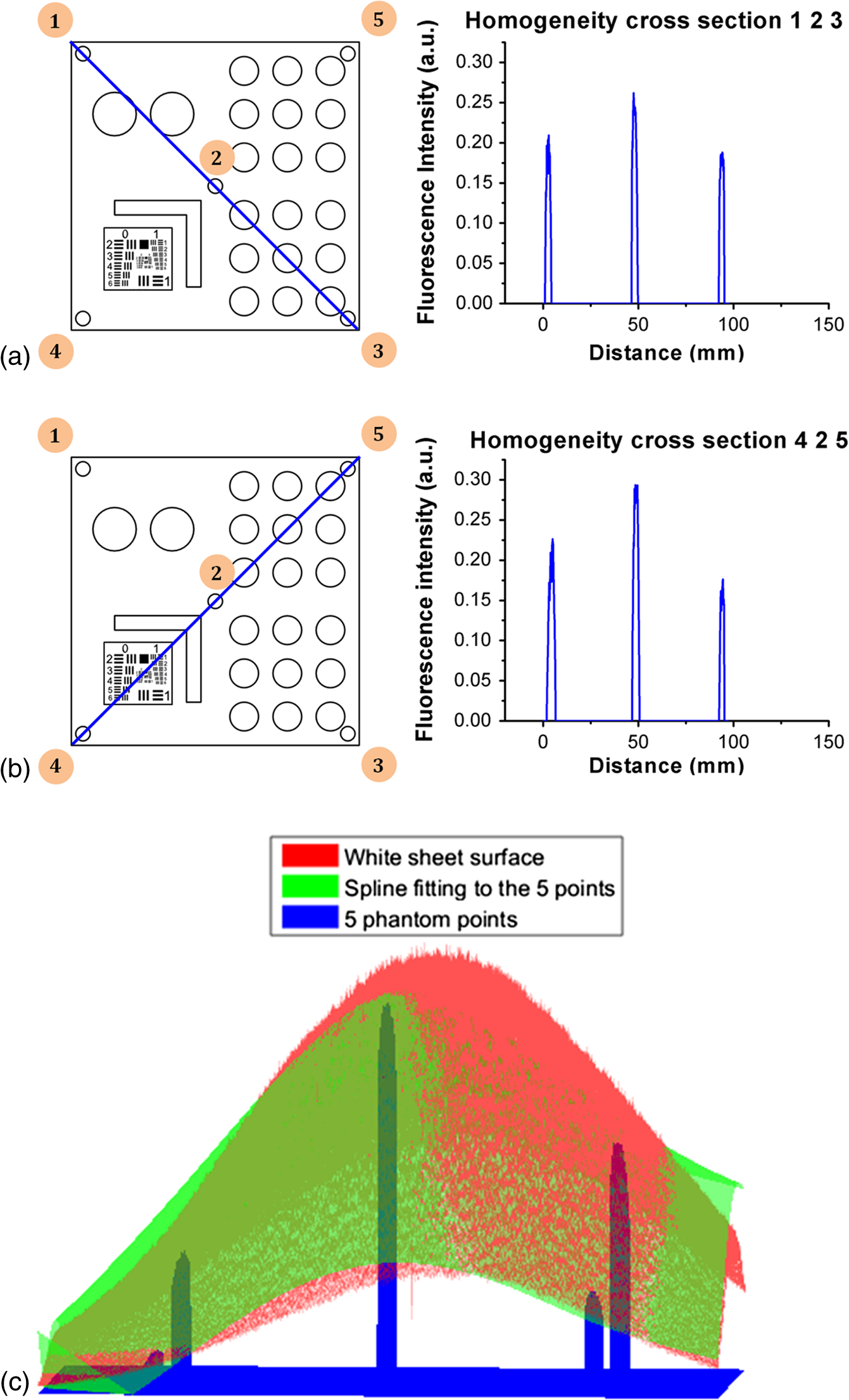 5.DiscussionThere is a large selection of camera systems and technologies developed to serve clinical fluorescence molecular imaging applications. The diversity in fluorescence detection directs the need for fluorescence phantoms that can seamlessly characterize the performance of a system or method over time or compare systems to each other. Ideally, a single phantom could offer comprehensive information on multiple system parameters with a single snapshot. The phantom constructed can assess multiple parameters of a camera while maintaining long-term stability requirements. The use of materials that do not vary their optical properties over time is critical. Phantoms that are employed for surgical training are usually manufactured based on hydrogels (agar and gelatin). Hydrogels impart tissue-like mechanical plasticity and make phantoms appropriate for surgical training and simulating intraoperative fluorescence imaging conditions. However, hydrogels do not maintain long-term optical property and shape stability (rigidity). Solid phantoms made of epoxy, polyester resin, or polyurethane offer a better solution for camera characterization, since they can maintain shape rigidity and can be machined to elaborate patterns and shapes. Silicone phantoms have also been proposed39 and offer an intermediate solution of maintaining plasticity and longer term optical property stability. Overall, we selected herein polyurethane as the base material due to the long-term stability of optical properties it provides.40,41 Scattering is imparted using three main approaches, i.e., using lipid microparticles, polymer microparticles, or white metal oxide powders.26 A widely used lipid-based scatterer is intralipid. Intralipid is an emulsion of soya oil in water that is sold commercially in calibrated lipid solutions for intravenous feeding and it is used primarily in liquid phantoms or gelatin phantoms. Regarding the polymer microspheres, polystyrene is a common microsphere employed and imparts a scattering spectrum that can be easily predicted with theoretical calculations.26 Nevertheless, the widespread availability of white metal oxide powder due to its use in manufacturing common white paint and its seamless integration with polyurethane often makes powder a preferred choice for solid phantoms.37,42,43 Absorbing powders and inks have been used as the main approaches to impart absorption in phantoms. India ink produces a relatively flat absorption spectrum across most of the visible and near-infrared wavelength.26 Regarding powders, a common powder employed in the literature is nigrosin.44 Other powders that have been reported are graphite powder45 and naphthol green B powder.33 Coffee has also been utilized as an absorbing agent since it attains an absorption spectrum similar to that of human melanin.44 In this work, we selected to use nigrosin as the absorbing pigment in the matrix material due to its seamless incorporation into polyurethane. Hemin was also used as an absorbing agent in the testing inlets because it resembles the optical spectrum of blood. The selection of the fluorescent moiety employed in a phantom is guided by its photostability and the ability to easily incorporate with the phantom’s base materials. QDots are preferred in the manufacturing of fluorescence phantoms due to their advantageous photostability over time and their ability to integrate in solid phantoms without quenching. QDots can fluoresce in the visible and near-infrared and are, therefore, well suited to simulate the fluorescence of biocompatible fluorophores such as ICG or FITC. The phantom has shown additional complexity over previously reported phantoms. Extended micromachining is necessary to impart the desired patterns in the different quadrants. In addition methods for fabricating multilayer structures were necessary, in particular for simulating fluorochromes at different depths, processes that include mold multilayer curing. Phantoms that represent higher complexity that simulate diverse structural and optical heterogeneities common in biological tissue may benefit by 3-D printing techniques45 and rapid prototyping of phantom with patient-oriented capabilities.46 The developed phantom that was presented above can be used as a universal comprehensive tool for the assessment of a system performance over time and for the comparison of different systems. Nevertheless, some parameters can also be determined in an absolute manner, e.g., the minimum fluorochrome amount that can be recorded, which indicates sensitivity or the illumination field homogeneity. A major advantage of the phantom over previous developments is that multiple system parameters can be measured in one snapshot. In Sec. 4, we discussed possible uses of the measurements performed. Overall different utilizations of the parameters analyzed and different phantom configurations may be proposed to validate the performance of different cameras. However, we expect the use of complex phantoms that could assess camera performance in one snapshot could become essential for standardization and calibration operations in fluorescence molecular imaging. In the future, such phantoms can be used for testing algorithmic and methodological approaches designed to improve the performance of fluorescence imaging, e.g., against the variation of optical properties or depth. In addition, a larger amount of wells can be implemented to test for a larger range of sensitivities and optical property variation. The latter would be important to better assess dynamic range characteristics of the camera, which are also critical parameters in clinical fluorescence imaging studies. AcknowledgmentsThe research leading to these results has received funding from the Deutsche Forschungsgemeinschaft (DFG), Germany [Leibniz Prize 2013; NT 3/10-1]. ReferencesM. Koch and N. Ntziachristos,
“Advancing surgical vision with fluorescence imaging,”
Annu. Rev. Med., 67 153
–164 ,
(2016). http://dx.doi.org/10.1146/annurev-med-051914-022043 Google Scholar
J. T. Alander et al.,
“A review of indocyanine green fluorescent imaging in surgery,”
Int. J. Biomed. Imaging, 2012 1
–26
(2012). http://dx.doi.org/10.1155/2012/940585 Google Scholar
M. Chu and Y. Wan,
“Sentinel lymph node mapping using near-infrared fluorescent methylene blue,”
J. Biosci. Bioeng., 107 455
–459
(2009). http://dx.doi.org/10.1016/j.jbiosc.2008.11.011 JBBIF6 389-1723 Google Scholar
A. Nour,
“Efficacy of methylene blue dye in localization of sentinel lymph node in breast cancer patients,”
Breast J., 10 388
–391
(2004). http://dx.doi.org/10.1111/tbj.2004.10.issue-5 BRJOFK 1075-122X Google Scholar
S. L. Troyan et al.,
“The FLARE((TM)) intraoperative near-infrared fluorescence imaging system: a first-in-human clinical trial in breast cancer sentinel lymph node mapping,”
Ann. Surg. Oncol., 16 2943
–2952
(2009). http://dx.doi.org/10.1245/s10434-009-0594-2 Google Scholar
Y. Fujisawa et al.,
“A custom-made, low-cost intraoperative fluorescence navigation system with indocyanine green for sentinel lymph node biopsy in skin cancer,”
Dermatology, 222 261
–268
(2011). http://dx.doi.org/10.1159/000327080 DERMEI 0742-3217 Google Scholar
Y. Tajima et al.,
“Sentinel node mapping guided by indocyanine green fluorescence imaging in gastric cancer,”
Ann. Surg., 249 58
–62
(2009). http://dx.doi.org/10.1097/SLA.0b013e3181927267 Google Scholar
G. M. van Dam et al.,
“Intraoperative tumor-specific fluorescence imaging in ovarian cancer by folate receptor- targeting: first in-human results,”
Nat. Med., 17 1315
–1319
(2011). http://dx.doi.org/10.1038/nm.2472 1078-8956 Google Scholar
T. J. Guzzo et al.,
“Intraoperative molecular diagnostic imaging can identify renal cell carcinoma,”
J. Urol., 195
(3), 749
–755
(2015). http://dx.doi.org/10.1016/j.juro.2015.09.093 Google Scholar
S. Singhall,
“Intraoperative imagery of breast cancer with folate-fitc (EC17),”
(2016) https://clinicaltrials.gov/ct2/show/NCT01994369 Google Scholar
M. B. Sturm et al.,
“Targeted imaging of esophageal neoplasia with a fluorescently labeled peptide: first-in-human results,”
Sci. Transl. Med., 5
(184), 184ra61
(2013). http://dx.doi.org/10.1126/scitranslmed.3004733 STMCBQ 1946-6234 Google Scholar
R. Atreya et al.,
“In vivo imaging using fluorescent antibodies to tumor necrosis factor predicts therapeutic response in Crohn’s disease,”
Nat. Med., 20 313
–318
(2014). http://dx.doi.org/10.1038/nm.3462 1078-8956 Google Scholar
W. Scheuer et al.,
“Drug-based optical agents: infiltrating clinics at lower risk,”
Sci. Transl. Med., 4 134ps11
(2012). http://dx.doi.org/10.1126/scitranslmed.3003572 STMCBQ 1946-6234 Google Scholar
W. Stummer et al.,
“Fluorescence-guided resection of glioblastoma multiforme utilizing 5-ALA-induced porphyrins: a prospective study in 52 consecutive patients,”
93 1003
–1013
(2000). http://dx.doi.org/10.3171/jns.2000.93.6.1003 Google Scholar
S. Esteves et al.,
“A pilot cost-effectiveness analysis of treatments in newly diagnosed high-grade gliomas: the example of 5-aminolevulinic acid compared with white-light surgery,”
Neurosurgery, 76 552
–562
(2015). http://dx.doi.org/10.1227/NEU.0000000000000673 NEQUEB Google Scholar
W. Stummer et al.,
“Predicting the ‘usefulness’ of 5-ALA-derived tumor fluorescence for fluorescence-guided resections in pediatric brain tumors: a European survey,”
Acta Neurochir. (Wien)., 156 2315
–2324
(2014). http://dx.doi.org/10.1007/s00701-014-2234-2 Google Scholar
L. M. Bernal García et al.,
“Fluorescence-guided resection with 5-aminolevulinic acid of meningeal sarcoma in a child,”
Child’s Nerv. Syst., 3
–6
(2015). http://dx.doi.org/10.1007/s00381-015-2703-9 Google Scholar
G. Themelis et al.,
“Real-time intraoperative fluorescence imaging system using light-absorption correction,”
J. Biomed. Opt., 14
(6), 064012
(2014). http://dx.doi.org/10.1117/1.3259362 JBOPFO 1083-3668 Google Scholar
J. S. D. Mieog et al.,
“Novel intraoperative near-infrared fluorescence camera system for optical image-guided cancer surgery,”
Mol. Imaging, 9
(4), 223
–231
(2010). http://dx.doi.org/10.2310/7290.2010.00014 Google Scholar
C. Chi et al.,
“Intraoperative imaging-guided cancer surgery: from current fluorescence molecular imaging methods to future multi-modality imaging technology,”
Theranostics, 4 1072
–1084
(2014). http://dx.doi.org/10.7150/thno.9899 Google Scholar
Ł. Szyc et al.,
“Development of a handheld fluorescence imaging camera for intraoperative sentinel lymph node mapping,”
J. Biomed. Opt., 20
(5), 051025
(2015). http://dx.doi.org/10.1117/1.JBO.20.5.051025 JBOPFO 1083-3668 Google Scholar
S. L. Troyan et al.,
“The FLARE intraoperative near-infrared fluorescence imaging system: a first-in-human clinical trial in breast cancer sentinel lymph node mapping,”
Ann. Surg. Oncol., 16 2943
–2952
(2009). http://dx.doi.org/10.1245/s10434-009-0594-2 Google Scholar
G. Themelis, J. S. Yoo and V. Ntziachristos,
“Multispectral imaging using multiple-bandpass filters,”
Opt. Lett., 33 1023
–1025
(2008). http://dx.doi.org/10.1364/OL.33.001023 OPLEDP 0146-9592 Google Scholar
L. M. A. Crane et al.,
“Intraoperative multispectral fluorescence imaging for the detection of the sentinel lymph node in cervical cancer: a novel concept,”
Mol. Imaging Biol., 13 1043
–1049
(2011). http://dx.doi.org/10.1007/s11307-010-0425-7 Google Scholar
M. D. Jafari et al.,
“The use of indocyanine green fluorescence to assess anastomotic perfusion during robotic assisted laparoscopic rectal surgery,”
Surg. Endosc., 27
(8), 3003
–3008
(2013). http://dx.doi.org/10.1007/s00464-013-2832-8 Google Scholar
B. W. Pogue and M. S. Patterson,
“Review of tissue simulating phantoms for optical spectroscopy, imaging and dosimetry,”
J. Biomed. Opt., 11
(4), 041102
(2006). http://dx.doi.org/10.1117/1.2335429 JBOPFO 1083-3668 Google Scholar
U. Resch-Genger et al.,
“Quantum dots versus organic dyes as fluorescent labels,”
Nat. Methods, 5 763
–775
(2008). http://dx.doi.org/10.1038/nmeth.1248 1548-7091 Google Scholar
X. Gao et al.,
“In vivo molecular and cellular imaging with quantum dots,”
Curr. Opin. Biotechnol., 16 63
–72
(2005). http://dx.doi.org/10.1016/j.copbio.2004.11.003 CUOBE3 0958-1669 Google Scholar
A. P. Alivisatos, W. Gu and C. Larabell,
“Quantum dots as cellular probes,”
Annu. Rev. Biomed. Eng., 7 55
–76
(2005). http://dx.doi.org/10.1146/annurev.bioeng.7.060804.100432 ARBEF7 1523-9829 Google Scholar
B. Zhu, J. C. Rasmussen and E. M. Sevick-Muraca,
“A matter of collection and detection for intraoperative and noninvasive near-infrared fluorescence molecular imaging: to see or not to see?,”
Med. Phys., 41 022105
(2014). http://dx.doi.org/10.1118/1.4862514 MPHYA6 0094-2405 Google Scholar
P. Krauter et al.,
“Optical phantoms with adjustable subdiffusive scattering parameters,”
J. Biomed. Opt., 20
(10), 105008
(2015). http://dx.doi.org/10.1117/1.JBO.20.10.105008 JBOPFO 1083-3668 Google Scholar
B. Zhu et al.,
“Validating the sensitivity and performance of near-infrared fluorescence imaging and tomography devices using a novel solid phantom and measurement approach,”
Technol. Cancer Res. Treat., 11
(1), 95
–104
(2012). http://dx.doi.org/10.7785/tcrt.2012.500238 Google Scholar
M. Roy et al.,
“Homogenized tissue phantoms for quantitative evaluation of subsurface fluorescence contrast,”
J. Biomed. Opt., 16
(1), 016013
(2011). http://dx.doi.org/10.1117/1.3528646 JBOPFO 1083-3668 Google Scholar
B. Leh,
“Optical phantoms with variable properties and geometries for diffuse and fluorescence optical spectroscopy,”
J. Biomed. Opt., 17
(10), 108001
(2012). http://dx.doi.org/10.1117/1.JBO.17.10.108001 JBOPFO 1083-3668 Google Scholar
A. M. De Grand et al.,
“Tissue-like phantoms for near-infrared fluorescence imaging system assessment and the training of surgeons,”
J. Biomed. Opt., 11
(1), 014007
(2006). http://dx.doi.org/10.1117/1.2170579 JBOPFO 1083-3668 Google Scholar
R. G. Pleijhuis et al.,
“Near-infrared fluorescence (NIRF) imaging in breast-conserving surgery: assessing intraoperative techniques in tissue-simulating breast phantoms,”
Eur. J. Surg. Oncol., 37 32
–39
(2011). http://dx.doi.org/10.1016/j.ejso.2010.10.006 Google Scholar
T. Moffitt, Y.-C. Chen and S. A. Prahl,
“Preparation and characterization of polyurethane optical phantoms,”
J. Biomed. Opt., 11
(4), 041103
(2006). http://dx.doi.org/10.1117/1.2240972 JBOPFO 1083-3668 Google Scholar
J. Glatz et al.,
“Concurrent video-rate color and near-infrared fluorescence laparoscopy,”
J. Biomed. Opt., 18
(10), 101302
(2013). http://dx.doi.org/10.1117/1.JBO.18.10.101302 JBOPFO 1083-3668 Google Scholar
G. Lamouche et al.,
“Review of tissue simulating phantoms with controllable optical, mechanical and structural properties for use in optical coherence tomography,”
Biomed. Opt. Express, 3 1381
(2012). http://dx.doi.org/10.1364/BOE.3.001381 BOEICL 2156-7085 Google Scholar
I. Noiseux et al.,
“Development of optical phantoms for use in fluorescence-based imaging,”
Proc. SPIE, 7567 75670B
(2010). http://dx.doi.org/10.1117/12.841887 PSISDG 0277-786X Google Scholar
M. L. Vernon et al.,
“Fabrication and characterization of a solid polyurethane phantom for optical imaging through scattering media,”
Appl. Opt., 38 4247
–4251
(1999). http://dx.doi.org/10.1364/AO.38.004247 APOPAI 0003-6935 Google Scholar
G. Wagnières et al.,
“An optical phantom with tissue-like properties in the visible for use in PDT and fluorescence spectroscopy,”
Phys. Med. Biol., 42 1415
–1426
(1997). http://dx.doi.org/10.1088/0031-9155/42/7/014 PHMBA7 0031-9155 Google Scholar
J. Baeten et al.,
“Development of fluorescent materials for diffuse fluorescence tomography standards and phantoms,”
Opt. Express, 15 8681
–8694
(2007). http://dx.doi.org/10.1364/OE.15.008681 OPEXFF 1094-4087 Google Scholar
R. B. Saager et al.,
“Multilayer silicone phantoms for the evaluation of quantitative optical techniques in skin imaging,”
Proc. SPIE, 7567 756706
(2010). http://dx.doi.org/10.1117/12.842249 PSISDG 0277-786X Google Scholar
M. Wang et al.,
“3D printing method for freeform fabrication of optical phantoms simulating heterogeneous biological tissue,”
Proc. SPIE, 8945 894509
(2014). http://dx.doi.org/10.1117/12.2041137 PSISDG 0277-786X Google Scholar
J. I. Gear et al.,
“Development of patient-specific molecular imaging phantoms using a 3D printer,”
Med. Phys., 41
(8), 082502
(2014). http://dx.doi.org/10.1118/1.4887854 MPHYA6 0094-2405 Google Scholar
|