|
|
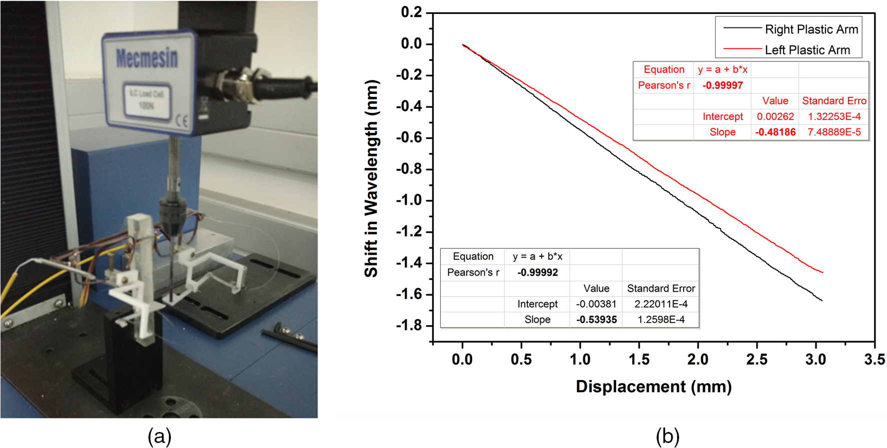
1.IntroductionAdvancement in science and technology has revolutionized the medical field, with more efficient emergency medicine, better intensive care, life supporting systems, and so on, increasing the survival rate. Nevertheless, severe brain and spinal cord injuries, in some cases, can lead to locked-in syndrome (LIS) and other forms of paralysis. LIS is a neurological disorder, which is a result of brainstem lesions, in which an individual is fully conscious and aware of the environment, however, with a complete paralysis of all voluntary muscles.1,2 Certain cases of LIS patients usually communicate through eye movements. Also, LIS may sometimes progress resulting in amyotrophic lateral sclerosis (ALS), also a neurological disorder, which is frequently accompanied by loss of clear vision. In such cases, interaction through visual modality may not be possible.3 Communication with these patients may become extremely difficult. These factors have led to the invention of assistive communication technologies such as a brain–computer interface (BCI).4 BCI is a mode of communication that relies on brain signals carried out between the brain and a computer. In principle, BCI works on the electrical signals generated due to brain activity during a particular thought, which will be acquired and processed for communication purpose.4,5 These brain signals are usually obtained by a process known as electroencephalogram, which requires electrodes to be placed on the scalp.6,7 In this method, the signal-to-noise ratio is poor along with low spatial resolution. Also, an invasive method known as electrocorticography is being used in which the electrodes are directly implanted into the brain beneath the skull on the surface of cortex to obtain higher resolution signals.8–11 This method has many disadvantages, primarily the invasiveness of the electrodes implanted.5,9 Further, the long-term usage of these implanted electrodes may lead to tissue reactions that could deteriorate the signal quality or result in electrode failure.5 Further, in conditions like ALS, this may severely affect the controlled action required to operate a BCI system and thereby making it difficult to select appropriate information from the BCI system.3,6 Fiber Bragg grating-based respiratory activity monitoring methodologies have been carried out previously. However, these studies mainly focus on the chest wall deformation in order to acquire the respiratory activity.12–14 The present study proposes a noninvasive, real-time dynamic fiber Bragg grating communication assistive device (FBGCAD) based on a fiber Bragg grating (FBG) sensor. The device is a breath pattern analyzer that acquires the exhalation force using an FBG sensor, which, on further processing, will provide a signal for an audio output. The nasal air flow is imparted onto an arm, which is transduced into strain variations on a cantilever, acquired by the FBG sensor bonded over it. The specific breath patterns are then programmed to produce predefined audio output commands providing a means of communication, thereby enhancing the quality of life of these paralyzed people. Individuals with LIS can be instructed to perform these specific breath patterns over the FBGCAD, which will subsequently produce an audio command. The developed FBGCAD has advantages like noninvasiveness, passive sensor element (no electric power needed for the sensor element), and wearability, which are in addition to the inherent advantages of the FBG sensor, such as high sensitivity, fast response, immunity to electromagnetic fields, and portability. 2.Fiber Bragg Grating SensorAn FBG is a periodic perturbation of refractive index of the core of a single-mode optical fiber along its axis.15 When a broadband light is launched into an FBG, a specific wavelength of light is reflected back, which satisfies the Bragg condition, and all other wavelengths are transmitted.16 This reflected wavelength of light, known as the Bragg wavelength (), is given by where is the periodicity of the grating and is the effective refractive index of the fiber. When an external perturbation, such as strain, temperature, and so on, affects the FBG, a shift in the Bragg wavelength is noticed. This property of FBG is used for its sensing applications.17–20 The effect of strain on an FBG sensor is expressed as Here and are the components of the strain-optic tensor, is the Poisson’s ratio, and is the axial strain change. In the present work, FBG sensors are fabricated using the phase mask method in a photosensitive Germania-doped silica fiber.21 The strain sensitivity of the fabricated FBG is approximately .22 The effect of temperature on FBG sensor is neglected in the present study as the experiment is carried out in a controlled environment, and also the test is carried out for a short time during which there is no temperature change observed.3.Fiber Bragg Grating Sensor-Based Communication Assistive DeviceThe FBGCAD comprises a spectacle frame, which is employed as the base structure to which the other instrumentations are attached. A plastic arm is pivoted at its midsection, making it swivel, with one end left free. The other end of this arm is attached to one end of a stainless steel cantilever. The other end of this cantilever is fixed to a plastic structure, which is made to be an extension of the spectacle frame. The plastic structure is attached by screws to the spectacle frame, which facilitates the plastic assembly movement along the frame as well as swiveling action about the frame, as shown in Fig. 1. Over the cantilever, the FBG sensor is bonded, which acquires the strain variation created on it. This constitutes the proposed FBGCAD. The FBGCAD is mounted on a subject with the spectacle frame, by positioning the free end of the plastic arm to reside below the nasal cavity. The exhalation during breathing will push the free end of the plastic arm, which in turn will pull the cantilever creating strain variations over it. Effectively, the proposed FBGCAD converts the exhalation force into strain variations on the cantilever, which is acquired by the FBG sensor and displayed as a waveform. This property of waveform generation during breathing is employed as the foundation for the development of a dynamic real-time communication methodology, which is further processed to output the specific programmed audio command. Also, it is imperative to note that the design of the FBGCAD is such that the flow of breath is not imparted directly on the FBG sensor. Hence, the temperature changes during breathing will not affect the device accuracy. Further, the change in ambient temperature is not considered because of the small experimental duration (10 s) during which the change in ambient temperature is negligible. In addition, the humidity changes do not affect the FBG sensors to a large extent. To make FBGs respond to humidity, coating with a polymer material sensitive to humidity variations on bare/etched FBGs is adopted. 4.Experimental ProcedureThe present study has been approved by the Institutional Human Ethics Committee (IHEC), Indian Institute of Science. The experiments carried out are within the guidelines of the IHEC for human studies. Also, the subjects have been detailed fully about the experimental procedure and their consent is obtained prior to the experiments. In the present study, 10 subjects aged 24 to 29 years (male and female), who have no known history of respiratory, lung, or cardiac diseases volunteered. The subjects are made to sit comfortably on a chair with a back rest and are allowed to adapt to the surroundings for 10 min. Thereafter, the subjects are asked to wear the FBGCAD like any other spectacle and breathe normally over the plastic arm, as shown in Fig. 2(a). The exhaled nasal air flow force causes the plastic arm to deflect, which in turn is converted to strain variations over the cantilever that is acquired by the FBG sensor bonded on it as illustrated in Fig. 2(b). The obtained breathing patterns are further analyzed for both amplitude and temporal characteristics. Fig. 2(a) FBGCAD mounted on a subject and (b) schematic representation of nasal air flow transduction into strain variation over the cantilever.  The data from the FBG sensor are recorded using a Micron Optics Interrogator SM 130-700 (which can acquire data at a sampling rate of 1 kHz) and are sent online to a program. This program has the ability to dynamically acquire the data from the interrogator, analyze, compare, and subsequently output an audio command in real time. The recorded breath patterns are compared with a set of predefined parameters. Recorded breath pattern is analyzed for the required parameters, which will decide the particular audio message to be output. For this purpose, various breath pattern parameters can be employed in the pattern analyzing process by the program. In the present study, a threshold crossover counter parameter is employed for the analysis. The threshold crossover counter analyzes the number of times the exhalation force has crossed the threshold within a stipulated duration of time. According to the count number, a corresponding predefined audio message will be output. A subject with a prior idea of the methodology may produce a breath pattern that matches with the predefined parameters and the corresponding audio command will be put out. The proposed FBGCAD along with program may act as a real-time communication methodology. 5.CalibrationThe developed FBGCAD is calibrated for its response of shift in wavelength of FBG sensor for a given displacement of the plastic arm. A Micro Universal Testing Machine (resolution of movement of ) is employed to provide the required displacement to both the plastic arms, as shown in Fig. 3(a). The response of shift in wavelength obtained from the FBG sensor is compared with the provided displacement obtained from the Micro Universal Testing Machine. Correlation coefficient of 0.99 is observed between the shift in wavelength and displacement provided on both right and left plastic arms, as shown in Fig. 3(b), showing good linearity response. Further, the slope of curve is being and for the right and left plastic arms, respectively, signifying a scaling factor of 0.53-nm blue shift in wavelength for 1-mm displacement on the right plastic arm and 0.48-nm blue shift in wavelength for 1-mm displacement on the left plastic arm. The change in scaling factor of the plastic arms on either side may be attributed to the positional offset of the FBG sensor placement on the cantilever on either side. The calibration curve shows that the response of the FBGCAD is almost linear on both sides with a variation in the scaling factor. 6.Results and DiscussionThe specific breath pattern obtained by the FBGCAD from a subject aged 26 years is illustrated in Figs. 4 and 5. These patterns are carried out by the subject as instructed, with prior knowledge about the same. To create these specific breath patterns, the subject needs to exhale with force in order to make the breathing curve crossover the threshold. In the present work, an algorithm is employed that has the ability to obtain the total number of crossovers of threshold by the breathing curve. This threshold of shift in wavelength of the FBG sensor is set to 0.1 nm, since the normal breathing response is observed to be below this threshold. It is imperative to understand that the employed algorithm only considers the number of times when the threshold is being crossed over and not the number of data points beyond the threshold. The time limit to carry out the breath pattern is fixed as 10 s, within which the subject has to produce a specific breath pattern. Fig. 4Nasal breath pattern obtained from right nostril of the subject which consists of four forced exhalations for time duration of 10 s.  Fig. 5Nasal breath pattern obtained from left nostril of the subject consisting of three alternating normal and force exhalations for time duration of 10 s.  During the first trial, the subject had been instructed to forcefully exhale four times with a pause between each exhalation. It is observed that the FBG strain response undergoes compression during exhalation and the magnitude of the compressive strain obtained is directly proportional to the quantum of force applied during exhalation over the plastic arm of the FBGCAD. Figure 4 illustrates the FBG response curve obtained from the right nostril of subject during the performance of the trial. When the FBG response curve crosses over the threshold, the algorithm count is increased by one count. The first forced exhalation causes the FBG response curve to crossover the threshold. By the end of the forced exhalation, the FBG response curve returns to its uncompressed normal state. The pause between successive exhalations (comprising of inhalation also) can be observed by the sustained uncompressed state of the FBG response curve. Similarly, after the first forced exhalation, three more forced exhalations along with in-between pauses are encountered, which crossover the threshold limit. It can be noticed that the pause time interval between successive forced exhalations is 0.63, 0.64, and 0.7 s, respectively. A total number of four threshold crossovers by the FBG response curve are obtained from the algorithm, which processes the data and outputs an audio command that has been assigned for this threshold crossover count. Further, another specific breath pattern from the left nostril of the same subject is illustrated in Fig. 5, where the subject has been instructed to alternately produce normal and forced exhalations with longer pause durations. The FBG response curve clearly depicts the alternating normal and forced exhalations. Also, it can be observed that out of a total number of six exhalations recorded within a time span of 10 s, only three exhalations are observed to be crossing over the threshold limit. The algorithm computes the threshold crossover count as 3 (as normal exhalations do not crossover the threshold) and the equivalent audio command will be put out. In addition, it can be seen that the time interval between successive forced exhalations is 3.5 s between the first and second exhalations and 3 s between the second and third exhalations, respectively. For an individual trial, the breath pattern obtained from either nostril is observed to be the same. Hence, the illustrated trials utilize the breath pattern obtained from one nostril in order to perform the temporal and spatial analysis. Furthermore, the illustrated trials prove the efficacy of the developed FBGCAD as a breath pattern analyzer to acquire forced as well as normal exhalations. Though the present study employs a simple threshold crossover algorithm, various other algorithms can be developed in conjunction with FBGCAD, which consider the time intervals between exhalations to provide a wider range of communicative messages. In the 10 subjects who volunteered for the present study, individual subjects were requested to perform five different breath patterns with varying threshold cross counters. The accuracy of the required audio command to be output for all the 10 subjects is shown in Table 1. The overall accuracy of the carried out trials on all the subjects is evaluated and is found to be 90% (average of accuracy of individual percentage). The trials during which the expected audio command is not put out may be attributed to the positional offset of the plastic arm below the nostril, i.e., the breath flow is not completely imparted on the plastic arm. Table 1Accuracy table for the audio command output of FBGCAD for 10 subjects.
The FBGCAD provides a hassle-free, easy to operate methodology that may be used on the bedside of a patient. In addition, FBGCAD comprises the ability to acquire data with 1-ms interval and to acquire data from both left and right nostrils simultaneously during a specific breathing trial. These major advantages along with the inherent advantages of FBG sensor make the proposed FBGCAD as an efficient breath pattern analyzer. Further, FBGCAD may be employed as a communication methodology for paralyzed patients. The limitation of the present study is that this methodology can only work for subjects having an ability to control the breath pattern between normal and forced exhalations. 7.ConclusionThe present study proposes a noninvasive, real-time dynamic breath pattern analyzer based on an FBG sensor. The proposed FBGCAD effectively converts the exhalation force into the strain variations on a cantilever, which in turn is acquired by the FBG sensor bonded over it. Two individual trials have been illustrated that prove the efficacy of the developed FBGCAD. Also, the FBGCAD can be easily worn as a spectacle, which eliminates any kind of discomfort or harm to the subject. This property makes FBGCAD an efficient way of communication for the paralyzed subjects. A test bench is currently under development to experimentally characterize the errors of the FBGCAD with a substantial sample size of paralyzed subjects. ReferencesS. R. Soekadar et al.,
“Fragmentation of slow wave sleep after onset of complete locked-in state,”
J. Clin. Sleep Med., 9
(9), 951
–953
(2013). http://dx.doi.org/10.5664/jcsm.3002 Google Scholar
S. Laureys et al.,
“The locked-in syndrome: what is it like to be conscious but paralyzed and voiceless?,”
Prog. Brain Res., 150 495
–611
(2005). http://dx.doi.org/10.1016/S0079-6123(05)50034-7 PBRRA4 0079-6123 Google Scholar
N. Birbaumer,
“Brain-computer-interface research: coming of age,”
Clin. Neurophysiol., 117 479
–483
(2006). http://dx.doi.org/10.1016/j.clinph.2005.11.002 CNEUFU 1388-2457 Google Scholar
D. De Massari et al.,
“Brain communication in the locked-in state,”
Brain, 136 1989
–2000
(2013). http://dx.doi.org/10.1093/brain/awt102 BRAIAK 0006-8950 Google Scholar
B. Graimann, B. Allison and G. Pfurtscheller, Brain-Computer Interfaces, 1
–27 Springer, Berlin Heidelberg
(2010). Google Scholar
J. J. Shih, D. J. Krusienski and J. R. Wolpaw,
“Brain-computer interfaces in medicine,”
Mayo Clin. Proc., 87
(3), 268
–279
(2012). http://dx.doi.org/10.1016/j.mayocp.2011.12.008 MACPAJ 0025-6196 Google Scholar
E. Niedermeyer and F. L. D. Silva, Electroencephalography: Basic Principles, Clinical Applications, and Related Fields, Lippincott Williams & Wilkins, Philadelphia
(2004). Google Scholar
L. R. Hochberg et al.,
“Neuronal ensemble control of prosthetic devices by a human with tetraplegia,”
Nature, 442 164
–171
(2006). http://dx.doi.org/10.1038/nature04970 Google Scholar
D. J. Krusienski and J. J. Shih,
“Control of a visual keyboard using an electrocorticographic brain-computer interface,”
Neurorehabil. Neural Repair, 25
(4), 323
–331
(2011). http://dx.doi.org/10.1177/1545968310382425 Google Scholar
D. J. Krusienski and J. J. Shih,
“Control of a brain-computer interface using stereotactic depth electrodes in and adjacent to the hippocampus,”
J. Neural Eng., 8
(2), 025006
(2011). http://dx.doi.org/10.1088/1741-2560/8/2/025006 1741-2560 Google Scholar
J. Shih and D. J. Krusienski,
“Signals from intraventricular depth electrodes can control a brain-computer interface,”
J. Neurosci. Methods, 203
(2), 311
–314
(2012). http://dx.doi.org/10.1016/j.jneumeth.2011.10.012 JNMEDT 0165-0270 Google Scholar
F. Silva et al.,
“Simultaneous cardiac and respiratory frequency measurement based on a single fiber Bragg grating sensor,”
Meas. Sci. Technol., 22 075801
(2011). http://dx.doi.org/10.1088/0957-0233/22/7/075801 MSTCEP 0957-0233 Google Scholar
E. Al-Fakih, N. A. Abu Osman and F. R. Mahamd Adikan,
“The use of fiber Bragg grating sensors in biomechanics and rehabilitation applications: the state-of-the-art and ongoing research topics,”
Sensors, 12
(10), 12890
–12926
(2012). http://dx.doi.org/10.3390/s121012890 Google Scholar
L. Dziuda et al.,
“Monitoring respiration and cardiac activity using fiber Bragg grating-based sensor,”
IEEE Trans. Biomed. Eng., 59
(7), 1934
–1942
(2012). http://dx.doi.org/10.1109/TBME.2012.2194145 IEBEAX 0018-9294 Google Scholar
W. W. Morey, G. Meltz and W. H. Glenn,
“Fiber Bragg grating sensors,”
Proc. SPIE, 1169 98
–107
(1989). http://dx.doi.org/10.1117/12.963022 PSISDG 0277-786X Google Scholar
A. Othonos,
“Fiber Bragg gratings,”
Rev. Sci. Instrum., 68
(12), 4309
–4341
(1997). http://dx.doi.org/10.1063/1.1148392 RSINAK 0034-6748 Google Scholar
A. D. Kersey et al.,
“Fiber grating sensors,”
J. Lightwave Technol., 15
(8), 1442
–1463
(1997). http://dx.doi.org/10.1109/50.618377 JLTEDG 0733-8724 Google Scholar
A. Othonos and K. Kalli, Fiber Bragg Gratings Fundamentals and Applications in Telecommunications and Sensing, Artech House, Boston, Massachusetts
(1999). Google Scholar
R. Kashyap, Fiber Bragg Gratings, Academic Press, San Diego, California
(1999). Google Scholar
B. A. Tahir, J. Ali and R. A. Rahman,
“Fabrication of fiber grating by phase mask and its sensing application,”
J. Optoelectron. Adv. Mater., 8
(4), 1604
–1609
(2006). Google Scholar
K. O. Hill et al.,
“Bragg gratings fabricated in monomode photosensitive optical fiber by UV exposure thorough a phase-mask,”
Appl. Phys. Lett., 62
(10), 1035
–1037
(1993). http://dx.doi.org/10.1063/1.108786 APPLAB 0003-6951 Google Scholar
S. M. Melle et al.,
“A Bragg grating-tuned fibre laser strain sensor system,”
IEEE Photonics Technol. Lett., 5
(2), 263
–266
(1993). http://dx.doi.org/10.1109/68.196025 IPTLEL 1041-1135 Google Scholar
|