|
|
1.IntroductionTwo-photon microscopy (TPM) is a powerful tool for imaging biological samples with high resolution, offering direct visualization of the behavior of cells in their natural environment.1,2 However, the image quality decreases rapidly as the focal point of the TPM penetrates deeper into the sample. Although dependent on the type of tissue, TPM has not yet been able to acquire images with high resolution deeper than about 1 mm.2,3 The fundamental depth limit is due to several factors including attenuation of the excitation light through absorption and scattering in the tissue and, importantly, aberrations that degrade both resolution and contrast, obscuring features of interest. These aberrations can be due to the optical inhomogeneity of the biological sample when penetrating through hundreds of microns of tissue (sample-induced aberration), and may also arise from an imperfect optical system (systematic aberration). In TPM, degradation of the beam focus contributes directly to signal loss at depth due to the square-law dependence of the measured signal on the peak intensity of the focused beam. Adaptive optics is known to enhance resolution and contrast at depth for TPM. Adaptive optical elements such as microelectromechanical systems (MEMS) deformable mirrors (DMs) can perturb the illuminating wavefront to precompensate for optical path length variations in the optical system as well as the sample.4–10 For example, Booth et al.4 incorporated a DM into a confocal microscope and showed good results with aberration correction in a mouse intestine specimen. Kong and Cui11 have demonstrated that the iterative multiphoton adaptive compensation technique can greatly improve the signal strength, resolution, and contrast for in vivo neuron imaging in mouse cortex at a large depth (). Others have shown promising results with a liquid crystal modulator for wavefront error compensation in biological samples.10 To date, these demonstrations have adopted a single wavefront correction for a particular depth. The correction is fixed for all points within the field of view, and may not optimally correct the aberrations throughout the field of view. In addition to managing aberrations, MEMS mirrors capable of large displacements can be used for dynamic focus control during imaging.12–14 Compared to mechanical means of focusing that translate the objective lens or the sample, focusing by modifying the wavefront curvature using an MEMS mirror introduces no vibrations and can be accomplished at much higher speeds. This opens up the possibility of imaging along oblique sections or more convoluted surfaces, and for multidepth imaging within a single image frame. A consequence of using an MEMS mirror (or a variable focus transmissive lens) for focus control is an introduction of additional systematic aberration. The objective lens and the relay lenses in a scanning laser microscope are optimized only for a particular imaging depth in the sample. When used to image at other depths, both spherical aberration and uncorrected off-axis aberrations arise. Combining a focus control mirror with an aberration correcting mirror leads to a flexible platform capable of aberration-corrected beam scanning throughout a three-dimensional (3-D) volume of tissue. This is the system we are developing that we call an active/adaptive two-photon microscope. A simplified diagram illustrating the capability of the instrument is shown in Fig. 1. In this diagram, it is assumed that the beam scanners and wavefront control mirrors are mutually conjugate to the aperture plane of the objective lens. The combination of focusing and aberration correction, synchronized with scanning, leads to control of the beam in three dimensions during image acquisition. Fig. 1With fast active wavefront modification, both the -position of the beam focus and local aberration may be continually controlled during beam scanning, enabling oblique, or contoured sectioning of the sample. In this diagram, it is assumed that the beam scanners and wavefront control mirrors are mutually conjugate to the aperture plane of the objective lens.  Fully flexible 3-D acquisition can be realized only if the focus and aberration correction mirrors can be modulated quickly enough to keep up with the fast-scan mirror. It is toward this end that we are characterizing MEMS mirrors, giving particular attention to the dynamic performance to ascertain whether they can be used to produce high Strehl ratio imaging while rapidly and continuously modulating the wavefront of the illumination beam. To frame the problem in a more quantitative way, we might consider segmenting a single fast scan into multiple zones, with a unique focus or aberration setting in each zone. For example, a 1 kHz fast scan might be accomplished using a galvo scanner following a sawtooth waveform with forward scan and retrace. Dividing the forward scan into five zones allows per zone. In this case, we might think about updating the DM at a frequency of , but we might demand a settling time that is small, perhaps 10% of the zone dwell time or . We would want to investigate the step response of the DM to ensure it is capable of this type of performance. On the other hand, we might think of interpolating between the five zones of the previous example and driving the mirror in a continuous trajectory. In that case, the mirror motion will be nearly periodic, with the same period as the scan mirror. But if, for example, the trajectory is to accurately follow a linear deflection during the forward scan and also accomplish a fast retrace, then the system bandwidth (DM and electronics) may need to be an order of magnitude higher than the scan frequency, or 10 kHz in our example. In this case, the more useful metric may be the frequency response of the system, rather than the step response. Having measured the actual step response or frequency response of a potential DM, we can then make an informed choice about the maximum galvo scan rate, or the complexity of the mirror trajectory that might be possible while maintaining imaging integrity. It is worth noting here that we are measuring the full system response by dynamically measuring the shape of the DM, and not simply considering update rates supported by the electronics. Furthermore, we examine how different Zernike modes respond, recognizing that air damping is the dominant mechanism setting the bandwidth of these mirrors, and different shapes are displacing the air under the mirror membrane in different ways. It will be shown that some Zernike modes exhibit a significantly faster response than others. In this paper, we evaluate the dynamic performance of two MEMS DMs for use in an active/adaptive two-photon microscope for deep tissue imaging. A simplified schematic of that instrument is shown in Fig. 2. A large-stroke DM (Revibro Optics MFC mirror, max deflection) is used for high-speed focus control and correction of depth-induced spherical aberration. This mirror, referred to as the “woofer,” is capable of large deflection but low spatial frequencies. A Boston Micromachines Corporation (BMC) Multi-DM ( max deflection) with 140 actuation channels is the “tweeter” that can handle aberrations with higher spatial frequency, including nonaxially symmetric modes (for example, astigmatism , coma , etc.). Our goal is to maintain a Strehl ratio exceeding 0.8 at any point in the 3-D imaging volume. Fig. 2The active/adaptive two-photon microscope with “woofer” and “tweeter” MEMS DMs for focus and aberration control.  We measure the surface height of both DMs using a stroboscopic phase-shift interferometer. Step response and sinusoidal steady-state response are measured using submicrosecond pulse widths, for a variety of specific aberration modes, in order to determine the maximum operating frequency for these mirrors. In addition to the response times of the mirrors, we quantify the dynamic behavior of the residual wavefront rms error when stepping the mirror. In this way, we determine the suitability of these wavefront modulation mirrors for our two-photon microscope. 2.Methods2.1.Selection of MEMS DM and Zernike Modes for TestSince speed is critical for active scanning and intrascan focus control and aberration correction, liquid crystal spatial light modulators that can achieve frame rates up to a few hundred Hertz are too slow and were not considered. On the other hand, commercially available MEMS DMs have electronic update rates of hundreds of kHz and published mechanical response times of tens of , making them candidates for this application. Furthermore, previous publications8,10,15 demonstrate that MEMS DMs are capable of correcting sample-induced aberration in a variety of tissue types up to imaging depths of a few hundred microns. To choose the proper MEMS DM for the active/adaptive microscope, we start with simulations of the systematic aberrations of the active/adaptive microscope in Zemax. This gives us a guideline for the selection of the MEMS DMs to be used in the active/adaptive microscope, and the Zernike modes that we will dynamically test. That simulation is described below. There is another consideration in choosing the MEMS DM, which is the type of mirror. There are three main types of MEMS DM that are commercially available, which are the segmented mirror with only piston motion, the segmented mirror with piston/tip/tilt motion, and the continuous face sheet mirror surface. We are interested to know whether a segmented mirror is capable of creating the shapes that meet our prescription with a residual error that is small enough to achieve diffraction-limited imaging. Using Fourier optics analysis to compute the aberrated point spread function (PSF), we found that a segmented, piston-only array with actuators like the BMC segmented multi-DM cannot reach a Strehl of 0.8 (our criteria for diffraction-limited imaging) when compensating the aberrations we expect to see. However, a continuous face sheet mirror, or a segmented mirror with piston/tip/tilt, such as the IrisAO PTT111 DM, provides sufficiently small residual error for a diffraction-limited PSF. Segmented, piston-only mirrors with a larger number of actuators such as the BMC kilo-DM might achieve our criteria, but at greater cost and complexity, and were not evaluated. Candidate mirrors we considered for the “tweeter,” therefore, included the tip/tilt/piston segmented IrisAO PTT111 DM with a mechanical response time and an mechanical stroke, and continuous face sheet mirrors such as the Alpao DM69 with an settling time and surface stroke, the Mirao 52-e with a stroke (unspecified settling time), and the BMC multi-DM with a response time and stroke. For the “woofer,” we considered the Alpao and Mirao mirrors, and the Revibro Optics 4-zone DM with a published settling time of less than . Using response time as the primary discriminator, with the cost and computational burden associated with a higher actuator count mirrors as a secondary consideration, we selected the BMC multi-DM continuous face sheet mirror to evaluate for the “tweeter” and the Revibro Optics DM to evaluate for the “woofer.” The Revibro DM, shown in Fig. 3, is based on a design described previously by Moghimi et al.12 It comprises a stretched metalized membrane, suspended over four concentric annular electrodes, and includes vertical channels through the backplate to control air damping. The device described in this paper has 3 rings of 16 holes per ring (Model No. M00120T), but other configurations can allow for more or less air damping. Fig. 3(a) Photomicrograph showing the electrodes and air hole pattern under the membrane and (b) top view of the mirror membrane.  It is worth noting that while the published technical data on the mechanical response of the MEMS DMs provide an estimate of the static and dynamic performance that is possible, it does not provide quantitative information on residual error that may be expected when driving to an actual prescription on the DM, or, just as important, how quickly the residual error will settle when switching from one prescription to another. Our testing directly measures these important performance measures. To know which Zernike modes will be most important in order to compensate systematic aberrations, we performed a Zemax simulation of an optical system that comprised the MEMS mirrors, relays, scan lens, tube lens, and a representative 1.0 numerical aperture (NA) water immersion objective lens selected from the patent literature.16 The MEMS mirrors are modeled as Zernike fringe surfaces, with the Zernike coefficients treated as variables for optimization. The focus control mirror is capable of a stroke of , which corresponds to an focus adjustment using in an aqueous sample, using the equation 17 where is the focus adjustment, is the peak to valley deflection of the MEMS DM, is the refractive index of the sample, and NA is the numerical aperture of the objective lens. Simulations were carried out over this full axial depth and for a lateral field of view of . We used an effective in our simulations.The dominant aberrations of the optical system that the DMs must correct are coma and spherical aberration [we use the American National Standards Institute (ANSI) indexing scheme for radial order and azimuthal frequency ], arising from the fact that the active focus control makes the objective lens operate at a focus location other than its optimum working distance. Other off-axis aberrations also come into play when the galvo scanners steer the beam to larger scanning angles, with appreciable contributions from both the relay optics and the objective lens. The simulation results show significant astigmatism , secondary astigmatism , secondary coma , trefoil , and secondary spherical aberration . The range of simulated aberration coefficients are summarized in Table 1. Note that we are using the “unnormalized” polynomials for our Zernike basis, given explicitly here: Table 1The dominant aberrations over a 500 μm field of view and full 80 μm focus range, from our Zemax model. The numbering of the Zernike terms follows the ANSI Zn,m indexing scheme for radial order n and azimuthal frequency m.
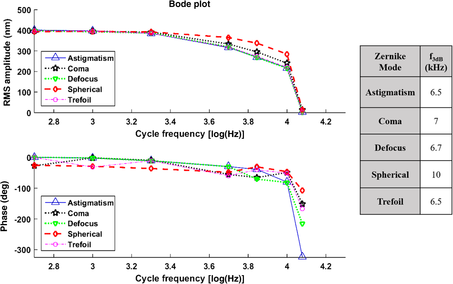
The higher-order aberrations are within the deflection range that can be compensated by the Boston Micromachines multi-DM with a stroke operating as the “tweeter,” with defocus and spherical aberration handled by the Revibro Optics mirror as the “woofer.” Based on these simulations, we chose to characterize astigmatism, coma, and trefoil on the BMC multi-DM in order to include both lower-order and higher-order shapes for comparison of the dynamic responses. For completeness, we also characterized primary spherical aberration using that mirror. Defocus and primary spherical aberration were characterized on the Revibro Optics DM. 2.2.Characterization by Stroboscopic Phase Shift Interferometry Synchronized to Mirror MovementStroboscopic interferometry can effectively freeze high-speed motion when the light pulses are sufficiently short and synchronized with the periodic movement of the MEMS DMs. In this case, exposure time is controlled by the laser pulse width rather than the integration time of the camera. The MEMS DM is driven with a periodic waveform. With proper delay, the pulsed laser diode illuminates the DM only at one specific phase of the periodic motion. The pulse width of the illumination is set short enough so as to maintain high fringe contrast for accurate phase unwrapping during data processing. We have constructed a custom phase-shifting Michelson interferometer for dynamic testing (Fig. 4). The sync hardware includes four function generators (two SRS DS345, HP 33120A, Sony Tektronix AFG320), which are capable of being controlled remotely. In order to ensure that the illumination takes place at the right phase of each periodic cycle, arbitrary waveforms for delays and laser pulse triggering are created and called through the control software. The control software is developed under the Labview environment, which interfaces to all the hardware including the function generators, a pulsed laser driver (DEI PCX-7410), camera, and piezo-electric stage. To control the BMC multi-DM, we use the high-speed X-driver with X-CL™ PCIe Interface Card. An SMA connector on the PCIe card allows external triggering to synchronize the movement of the DM and the strobe pulse. The 140 actuators on the BMC DM are set digitally, within the MATLAB environment, by assigning a matrix of values from 0 to 65535 mapped to a voltage range from 0 to 300 V. On the other hand, the Revibro DM is driven entirely in analog. For this, a two-channel function generator (Sony Tektronix AFG320) and a two-channel high speed high voltage amplifier (Trek 603 Piezo Driver/Power Amplifier) are coupled to provide the voltage needed for the electrostatic actuation of the metal coated polymer membrane on the Revibro DM. Although this mirror has four concentric actuation electrodes, potentially allowing fine control over higher-order spherical aberration (secondary spherical aberration and tertiary spherical aberration ), for dynamic testing, we connected the central two and outer two electrodes together to form a two-zone mirror. The two-zone control was sufficient to modulate primary spherical aberration independently from the focus setting. 2.3.Mirror TrainingWith a phase-shifting Michelson interferometer, we are able to capture the surface height of the DMs. For analysis, the surface height is fit to 55 spatially orthogonal aberration modes (the unnormalized Zernike modes, up to order ), with the surface deflection S reconstructed according to . Since the commercially available DMs do not come with a mapping between surface shapes and control voltages, the first task was to train the mirror to the target shapes we elected to test. An iterative algorithm was used to find the control voltages that produced a single Zernike mode of desired amplitude while suppressing all other terms. In brief, the algorithm is as follows. A target surface shape was calculated for the desired mode. The mirror surface deflection was then measured using the interferometer, and the height of a region near the center of each actuator zone was compared to the target for that location. The control voltage is updated according to , where is the error between the target height and the measured height and is the control voltage, for the ’th zone and the ’th iteration. The gain parameter is chosen to facilitate convergence of the algorithm. We work with the square of the voltage, since the electrostatic force varies as the square of the applied voltage. It should be noted that because the BMC mirror and the Revibro mirror are electrostatically actuated they can be deflected only in one direction. On the other hand, the Zernike modes exhibit both positive and negative displacements. We, therefore, bias the mirror with an initial deflection, with the Zernike mode superimposed on that initial shape. For the BMC mirror, this initial deflection is an “active flat” surface with each actuator deflected to 50% of the rated maximum deflection. For the Revibro mirror, the initial deflection is a midrange defocus setting that is purely parabolic in shape. We were successful in training each of the test modes, with residual contribution from all other modes less than 20 nm rms. Height maps from these trained shapes on the BMC multi-DM are shown in Fig. 5 (all mode amplitudes in the figure are 400 nm). Similarly, control voltages were determined to train both defocus and primary spherical aberration on the Revibro mirror. Fig. 5(a) Standard Zernike shapes trained on the BMC multi-DM using a closed loop feedback training process. From left to right, astigmatism, coma, defocus, primary spherical, and trefoil. The amplitude for these standard Zernike shapes is 400 nm. The residual rms error on these shapes is 5, 19, 7, 20, and 12 nm for astigmatism, coma, defocus, primary spherical, and trefoil, respectively. (b) 300 nm primary spherical aberration superimposed on defocus trained on the Revibro DM. Scale bars show height in nm.  2.4.Description of Specific Tests Performed2.4.1.Zernike mode frequency responseFor continuous intrascan correction of aberrations such as coma or astigmatism, the time dependence of any particular wavefront shape will be nearly periodic, synchronized to the fast-scan mirror. In order to quantify the capability of the DM, we chose to measure a sinusoidal steady-state frequency response for specific aberration modes. The mode amplitude is varied sinusoidally at a particular frequency, and the mirror response is measured in terms of amplitude and phase delay of that specific mode relative to the driving waveform. These are plotted versus frequency using a Bode style plot. As shown in Fig. 6, a sampled sinusoidal signal at frequencies ranging from near DC to several kHz drives the MEMS DM. For the BMC DM, a pulse triggers a new voltage map to be assigned to the 140 actuators, with 12 shapes per period comprising the stepwise sinusoidal trajectory. For example, in the figure, the mirror is driven to 12 different amplitudes of trefoil, with the amplitude following a sinusoidal time dependence. Synchronously, the phase-shifting interferometer strobe is progressively set to six different sampling delays, generating six different height maps. Each height map is decomposed into Zernike modes, and the measured amplitude of the mode of interest is then curve fit to find the magnitude and the phase relative to the driving phase. Using the X-driver and high speed camera card (X-CL™ PCIe Interface Card) we can update the BMC voltage map at a maximum speed of 400 kHz. This sets a maximum sinusoidal test frequency of . Our tests included a maximum sinusoid frequency of 12.5 kHz. Fig. 6Stroboscopic imaging for frequency response. Twelve frames of 12 different amplitudes (trefoil shown in this figure) form a periodic sinusoidal movement on the BMC DM, and the submicrosecond light illumination pulses take place at 30 deg, 90 deg, 150 deg, 210 deg, 270 deg, and 330 deg in each cycle to capture the instantaneous movement of the BMC DM.  2.4.2.Zernike mode step responseTo capture fast transients of the MEMS DM with a periodic square-wave driving signal, we use a short laser diode pulse ranging from 400 ns to . The short pulse width ensures that averaging during image acquisition on the charge coupled device camera will not degrade the fringe contrast of the interferogram. As shown in Fig. 7, a pulse train with a proper delay has been created to capture 100 points spanning during the rising edge and falling edge for the step response. 2.4.3.RMS surface errorUnder the weak aberration limit, a Strehl intensity (diffraction limited) corresponds to an rms wavefront error less than of the operating wavelength. Therefore, when plotted against time, the rms error can function as a good indicator to tell not only how fast the mirror can achieve the desired shape, but also how soon the MEMS DM can compensate the target aberration to achieve diffraction-limited imaging. After the Zernike shape fitting, we are able to gather a matrix that contains the amplitudes of each Zernike polynomial, from which the residual rms error is calculated using the following equation: where is the amplitude of each Zernike term from the surface height fitting, is the amplitude of the target shape of the specific Zernike mode, and is the rms normalization factor of the Zernike polynomial for the specific term Note that our error is for the mirror surface, so in order to maintain a wavefront error less than we must keep the mirror surface height error to less than , since the mirror is used at near normal incidence where the wavefront retardation upon reflection is twice the mirror height variation. Assuming a two-photon excitation wavelength of , the error threshold for is 36 nm rms. This threshold value is used when analyzing the error relaxation responses.3.Results3.1.BMC Multi-DM3.1.1.Frequency responseFigure 8 plots the magnitude and phase response for five different Zernike modes on the BMC multi-DM. The results show that astigmatism, defocus, and trefoil exhibit a 3-dB frequency near 6.5 kHz. Coma has a 3-dB frequency closer to 7 kHz, while spherical aberration has the largest 3 dB bandwidth near 10 kHz. All modes were driven with the same 400 nm amplitude, but the membrane shapes are different, as are the peak-to-peak deflections. Defocus, astigmatism, coma, and trefoil all have peak-to-peak displacements of the membrane equal to twice the Zernike amplitude (800 nm), while spherical aberration has a peak to peak displacement of 1.5 times the amplitude (600 nm). The higher 3-dB frequency of spherical aberration thus seems to correlate to a smaller peak-to-peak membrane deflection, but the damping due to air flow beneath the membrane is important, and its dependencies on mode shape and amplitude have not been separated here. It is noteworthy that the frequency response for all modes shows a smooth roll-off with no peaking, indicating that these mirrors are over-damped and exhibit no resonances at least up to 12.5 kHz. Fig. 7Stroboscopic imaging for a step response. The submicrosecond illumination pulses capture the instantaneous movement of the rising edge during a step from flat to the target amplitude of a specific Zernike mode (trefoil shown in this figure). By using proper delays, we evaluate the full evolution of the mirror shape.  3.1.2.Step responseFigure 9 shows step response measurements for five different Zernike modes. Each mode was driven from the active flat membrane position to the mode shape with a 400-nm amplitude. Rise times (10% to 90%) are calculated and tabulated in Table 2. Rise times measured for all five aberration modes ranged from 44 to . By computing the rms surface deviation from the final target shape, we can plot rms surface error versus time in an error relaxation plot. Although the step height for each mode has the same 400 nm amplitude, these are the nonnormalized Zernike modes and so exhibit a different rms deviation. That is reflected in the starting rms error value for each of the five modes. Note that the RMS error includes the error contribution from all modes, including the mode that is being stepped; the full transient membrane shape is accounted for. A meaningful metric is the error settling time, when the overall mirror rms error is less than , corresponding to Maréchal’s criterion for . With , this limit is 36 nm rms, which is indicated by the solid red line in Fig. 9. Error settling time for all five of these mode steps is less than . The results are tabulated in Table 3. Fig. 9Step response for different tested Zernike modes at a step from 0 to 400 nm in amplitude on the BMC multi-DM (referred to the right side y-axis). The rms error is also plotted against time for each Zernike mode step (referred to the left y-axis). The solid line at 36 nm RMS error is the threshold to recover to 80% Strehl, according to the Marechal’s criterion ().  Table 2Summary of the rise time for the BMC multi-DM.
Table 3The time needed for the BMC MEMS DM to settle below 36 nm of RMS error to achieve diffraction-limited imaging.
We also investigated the influence of mode amplitude on step response and error settling time. Figure 10 shows a family of step response curves for astigmatism with amplitudes ranging from 100 to 500 nm, and also for . Rise times range from for the smallest step to for the 400-nm step. Error settling times show a particularly strong dependence on mode amplitude, since the threshold of 36 nm error is barely exceeded for the full amplitude 100 nm astigmatism step. Even the 500 nm astigmatism step settles to within the 0.8 Strehl limit within . Table 2 summarizes the rise times, and Table 3 summarizes the wavefront error settling times for all five tested modes for amplitudes from 100 to 500 nm and for . Within this range of correction, all of the steps reach the threshold for diffraction-limited precision in less than . 3.2.Revibro Optics DM3.2.1.Step responseFigure 11 plots the response for five different defocus steps of the Revibro DM. The peak-to-peak deflection is twice the Zernike amplitude, so that 1- and steps correspond to mirror sags of 2 and , respectively. We see that the step response is somewhat underdamped with a slight overshoot, so that the error plots show some oscillation. The smaller step from 2.9 to also shows a slight overshoot. Rise times (10% to 90%) range from 28 to for these tests. Fig. 11Step response of active focus control with Revibro MEMS DM at 0 to 1, 0 to , 2.9 to , 0 to 5, and 0 to . The RMS error is also plotted against time at the rising edge of a step response for different amplitudes in focus control on the Revibro multi-DM.  Because of the ringing in the step response, the settling times are a bit longer for the larger focus steps, all of which require at least (up to for maximum deflection at ) to reach a diffraction-limited shape. The smaller defocus step from 2.9 to has an error that settles much faster in about . The rise times and settling times for defocus on the Revibro mirror are summarized in Table 4. Table 4Summary of dynamic performance for defocus on Revibro MEMS DM.
Finally, we measured the step response for a change in spherical aberration on the Revibro mirror. We characterized mode amplitudes of 200, 400, and 600 nm. These are superimposed on a defocus bias of ( mirror sag). The results are plotted in Fig. 12. More ringing is observed for these steps, showing that the spherical aberration shape is less damped in this free-standing membrane. The rise times are quite short, less than . The error settling times are variable, ranging from 13 to , affected by the oscillation in the step response. The rise times and error settling times for primary spherical aberration on the Revibro DM are summarized in Table 5. Fig. 12The step response for different amplitudes in spherical aberration correction on the Revibro MEMS DM. The RMS error (excluding defocus) during the step response is also plotted (referred to the -axis on the left side). 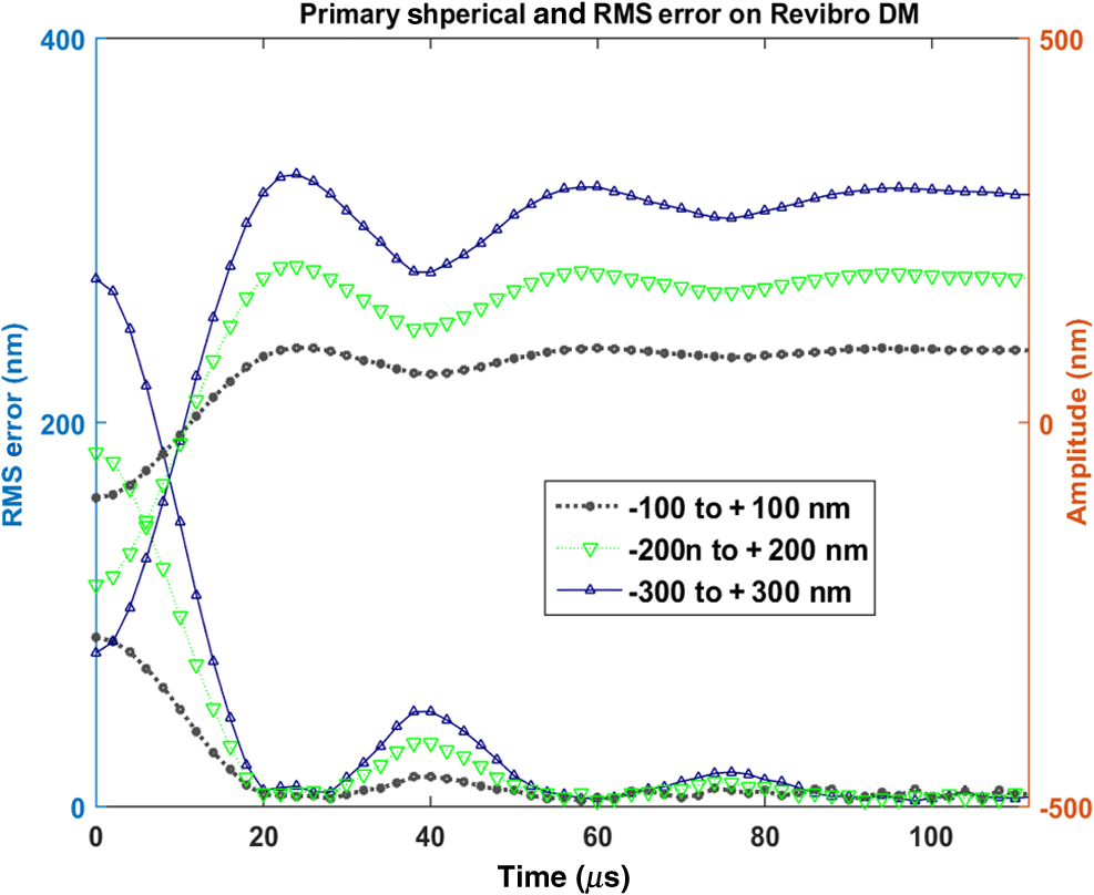 Table 5Summary on dynamic performance for primary spherical aberration on Revibro MEMS DM.
4.Discussion and ConclusionsWe evaluated MEMS DMs from BMC and Revibro Optics to assess the dynamic performance for active focus control and aberration correction in an active/adaptive two-photon microscope. We observed that both of the mirrors could be trained to the desired shapes with a small rms error or less for these low-order aberrations. For smoothly changing aberrations, such as systematic aberrations that depend on the scan angle of the beam, sinusoidal steady-state frequency response may be a useful metric. As shown in the results for the BMC multi-DM, the 3-dB frequency was at least 6.5 kHz for all modes tested, and as high as 10 kHz for spherical aberration. While not measured directly here, the 3-dB frequency for both defocus and spherical aberration correction using the large stroke Revibro Optics mirror are calculated from the measured step response to be in excess of 9 kHz. In the context of on-the-fly focus adjustment during beam scanning, these mirrors should be able to adjust focus over the full DM deflection range and compensate aberrations for simple oblique sections or other “simple” focus profiles when scanning at low kHz scan rates using a nonresonant galvo scanner. This is the most typical setup for two-photon imaging. With a resonant scanner, these mirrors could likely support only moderate-depth oblique sections at frequencies up to 8 kHz, since larger deflections are more heavily damped. Active focusing and aberration correction during high-speed (8 kHz) scanning remains an open question requiring further experimental investigation. For scan profiles that are discontinuous when scanning the beam across the sample, we may consider the rise time and rms error settling time as useful metrics. Examples of discontinuous scans might be different focus depths within the imaging field of view, or multiple adaptive zones within the frame, that require resetting the aberration correction prescription multiple times during a horizontal line scan. Similarly, a fast scan retrace during a sawtooth scan waveform might require a reset of the DM prescription. We found that error settling times are consistently less than for both the BMC and the Revibro mirror for aberration correction and small defocus steps; smaller steps settle considerably faster. Larger defocus steps on the Revibro mirror required longer to settle: for a step, for a step, and for a step. Even the largest defocus step will settle to a diffraction-limited profile in the time it would take a galvo scan mirror to finish its retrace in our hypothetical 1 kHz sawtooth scanning system with a forward scan and retrace. The measured dynamic performance of both the BMC mirror and the Revibro Optics mirror demonstrates that these mirrors can support intrascan correction during active/adaptive microscopy at scan rates up to about 1 kHz. With this control of both focus and aberrations, we can achieve nearly arbitrary focal spot trajectories at this speed in the tissue, turning the two-dimensional scanning microscope into an agile 3-D imaging tool. Furthermore, we hope to combine this agile scanning with adaptive correction of sample-induced aberrations to ultimately deliver diffraction-limited imaging throughout the accessible 3-D object space. AcknowledgmentsThis project was supported by the National Science Foundation under Project 1338133. The test devices were provided by Boston Micromachines Corporation and Revibro Optics LLC. The authors are thankful for assistance provided by Sarah Lukes. David L. Dickensheets and Christopher L. Arrasmith disclose that they have a financial interest in Revibro Optics. Revibro Optics mirrors were fabricated with use of the Montana Nanofabrication Facility, which is supported as part of the NSF National Nanotechnology Coordinated Infrastructure Program under Award 1542210. ReferencesK. Svoboda et al.,
“Spread of dendritic excitation in layer pyramidal neurons in rat barrel cortex in vivo,”
Nat. Neurosci., 2
(1), 65
–73
(1999). http://dx.doi.org/10.1038/4569 NANEFN 1097-6256 Google Scholar
D. Kobat et al.,
“Deep tissue multiphoton microscopy using longer wavelength,”
Opt. Express, 17
(16), 13354
–13364
(2009). http://dx.doi.org/10.1364/OE.17.013354 OPEXFF 1094-4087 Google Scholar
D. Kobat, N. G. Horton and C. Xu,
“In vivo two-photon microscopy to 1.6-mm depth in mouse cortex,”
J. Biomed. Opt., 16
(10), 106014
(2011). http://dx.doi.org/10.1117/1.3646209 JBOPFO 1083-3668 Google Scholar
M. J. Booth et al.,
“Adaptive aberration correction in a confocal microscope,”
J. Biomed. Opt., 99
(9), 5788
–5792
(2002). http://dx.doi.org/10.1073/pnas.082544799 JBOPFO 1083-3668 Google Scholar
P. N. Marsh, D. Burns and J. M. Girkin,
“Practical implementation of adaptive optics in multiphoton microscopy,”
Opt. Express, 11
(10), 1123
–1130
(2003). http://dx.doi.org/10.1364/OE.11.001123 OPEXFF 1094-4087 Google Scholar
P. Tsai et al.,
“Spherical aberration correction in nonlinear microscopy and optical ablation using a transparent deformable membrane,”
Appl. Phys. Lett., 91 191102
(2007). http://dx.doi.org/10.1063/1.2804014 APPLAB 0003-6951 Google Scholar
A. Mertz and J. Leray,
“Rejection of two-photon fluorescence background in thick tissue by differential aberration imaging,”
Opt. Express, 14 10565
–10573
(2006). http://dx.doi.org/10.1364/OE.14.010565 OPEXFF 1094-4087 Google Scholar
D. Debarre et al.,
“Image-based adaptive optics for two-photon microscopy,”
Opt. Lett., 34
(16), 2495
–2497
(2009). http://dx.doi.org/10.1364/OL.34.002495 OPLEDP 0146-9592 Google Scholar
Y. Zhou, T. Bifano and C. Lin,
“Adaptive optics two-photon fluorescence microscopy,”
Proc. SPIE, 6467 646705
(2007). http://dx.doi.org/10.1117/12.705045 PSISDG 0277-786X Google Scholar
N. Ji, D. E. Milkie and E. Betzig,
“Adaptive optics via pupil segmentation for high-resolution imaging in biological tissues,”
Nat. Methods, 7 141
–147
(2009). http://dx.doi.org/10.1038/nmeth.1411 1548-7091 Google Scholar
L. Kong and M. Cui,
“In vivo fluorescence microscopy via iterative multi-photon adaptive compensation technique,”
Opt. Express, 22
(20), 23786
(2014). http://dx.doi.org/10.1364/OE.22.023786 OPEXFF 1094-4087 Google Scholar
M. Moghimi et al.,
“High speed focus control MEMS mirror with controlled air damping for vital microscopy,”
Microelectromech. Syst., 22
(4), 938
–948
(2013). http://dx.doi.org/10.1109/JMEMS.2013.2251320 Google Scholar
M. Moghimi et al.,
“MOEMS deformable mirrors for focus control in vital microscopy,”
J.Micro/Nanolithogr. MEMS MOEMS, 10
(2), 023005
(2011). http://dx.doi.org/10.1117/1.3574129 Google Scholar
S. J. Lukes and D. L. Dickensheets,
“Agile scanning using a MEMS focus control mirror in a commercial confocal microscope,”
Proc. SPIE, 8949 89490W
(2014). http://dx.doi.org/10.1117/12.2042249 PSISDG 0277-786X Google Scholar
J. Tang, R. Germain and M. Cui,
“Superpenetration optical microscopy by iterative multiphoton adaptive compensation technique,”
Proc. Natl. Acad. Sci. U. S. A., 109
(22), 8434
–8439
(2012). http://dx.doi.org/10.1073/pnas.1119590109 Google Scholar
D. L. Dickensheets,
“Requirements of MEMS membrane mirrors for focus adjustment and aberration correction in endoscopic confocal and optical coherence tomography imaging instruments,”
J. Micro/Nanolithogr. MEMS MOEMS, 7
(2), 021008
(2008). http://dx.doi.org/10.1117/1.2911024 Google Scholar
BiographyChristian Chunzi Archer-Zhang received his BS degree in biomedical engineering from Hong Kong Polytechnic University in 2007, and his BS and MS degrees in electrical engineering from Montana State University in 2013. Currently, he is a PhD candidate at Montana State University. His research interests include adaptive optics for biomedical imaging, confocal microscopy, two-photon microscopy, bioinstrumentation, and cancer therapy. Warren B. Foster is a senior undergraduate student pursuing a bachelor's degree in electrical engineering at Montana State University with a minor in mathematics. His interests include MEMS adaptive optics and control theory. He hopes to pursue a graduate degree in electrical engineering after completing his current degree. Ryan D. Downey is a graduate student pursuing an advanced degree in electrical engineering at Montana State University. His interests include the closed loop control of MEMS adaptive optical systems with an emphasis on field programmable gate arrays (FPGAs) as a potential development platform. Christopher L. Arrasmith receved his BS and MS in electrical engineering from Montana State University in 2006 and 2008, respectively. After several years developing MEMS-based display technologies and metrology systems in industry, he founded Revibro Optics in 2015 and is currently the president and CEO. His expertise in micro-optics and MEMS has driven the development of the variable focus mirrors produced by Revibro Optics. David L. Dickensheets received his BSEE degree from the University of Colorado in 1985, his MSEE degree from the University of Washington in 1988, and his PhD from Stanford University in 1997, all in electrical engineering. He has been at Montana State University since 1997, where he is a distinguished professor of electrical and computer engineering. His research interests include optical microscopy and spectroscopy, MOEMS, and microfabrication techniques for miniature optical instruments. |
||||||||||||||||||||||||||||||||||||||||||||||||||||||||||||||||||||||||||||||||||||||||||||||||||||||||||||||||||||||||||||||||||||||||||||||||||||||||||||||