|
|
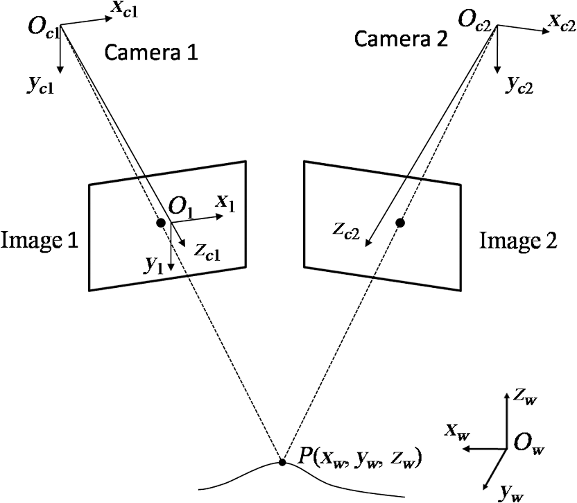
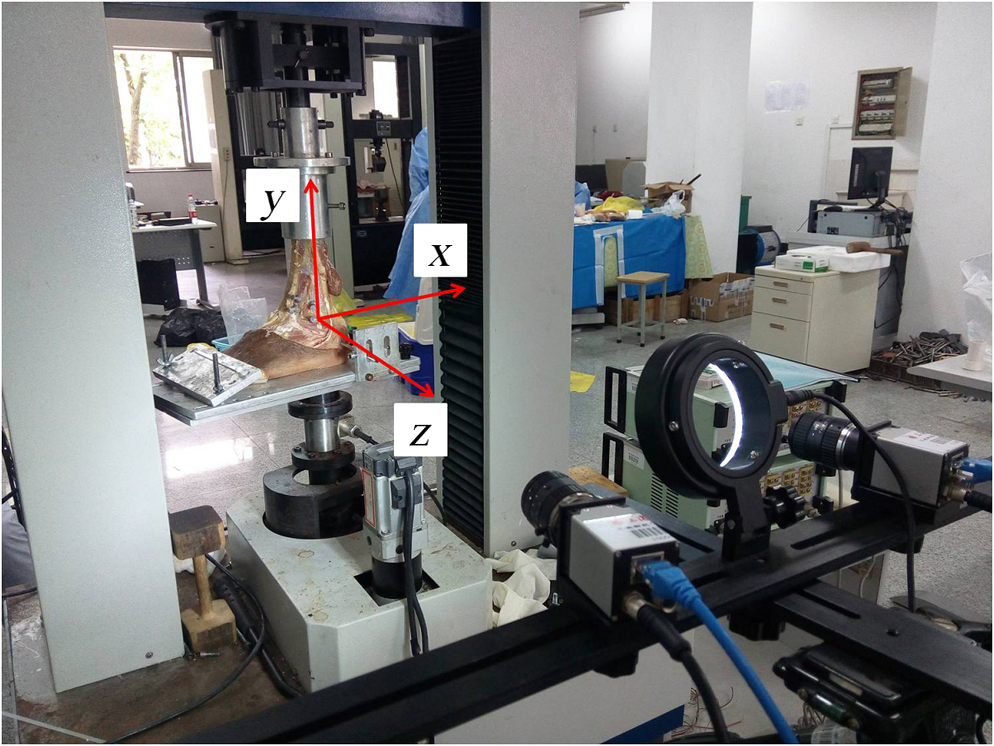
1.IntroductionAn assessment of the mechanical properties of biological tissues is often performed to understand the constitutive relationship of natural tissues and can be helpful for improving clinical treatments. Concerning the need for strain measurements in this pursuit, recent developments of digital image correlation (DIC) have made it appealing for biomechanical studies. Indeed, there are many distinct advantages such as the simple optical arrangement, high accuracy, and large range of measurement. DIC is an optical method that employs image registration techniques for achieving accurate two-dimensional (2-D) and three-dimensional (3-D) measurements from changes in images. This technique is most often used to measure engineering deformation including displacement and strain.1,2 With use of the Newton–Raphson algorithm, DIC can achieve 0.01 pixel precision when a bicubic interpolation is adopted.3 The strain components are calculated from the displacement by a discrete difference of derivatives. As an optical noncontact method, DIC has been applied for determining the mechanical properties of soft and hard biological tissues.4–7 This technique has also been used for characterizing the integrity of implants and joint replacements. For instance, loosening of the femoral component in total hip replacements as a result of cyclic loading has been evaluated using DIC.8,9 In cemented total knee arthroplasty, the micromotion and strains at the cement-trabeculae interface were quantified to demonstrate the loss of interlock between cement and trabeculae at the tibial interface. This problem could potentially lead to increased circulation of interstitial fluid, which in turn causes fluid-induced resorption of the trabeculae.10 Metal and ceramic implants and heterotopic ossification have been reported in surgical treatments of total hip, knee, cervical, and lumbar arthroplasty. The primary goal of these treatments is to recover the basic function of the human body, which often is focused on restoring the range of motion, and reducing pain and suffering. In these treatments, a 3-D kinematic analysis is needed for evaluating the range of movement before and after the treatment.11–14 It is customary to use typical motion tracking systems that utilize an array of active or passive markers attached to the human body to transmit infrared light to a multiple camera system. One attractive quality of this approach is that the 3-D coordinates of the markers can be accurately determined at a rate of 200 Hz. However, the system is expensive. In addition, since the markers must be attached onto the target, the existing 3-D kinematic analysis system is a contact measurement method, which is a drawback. As the existing 3-D kinematic analysis system depends strictly on the reflective markers, it is susceptible to interference of other heat sources. This paper presents the development of a noncontact video camera system for 3-D motion tracking based on DIC. The artificial or natural surface texture can be used as markers and the corresponding 3-D coordinates are reduced based on feature point correlation matching and photogrammetry. A real-time 3-D-DIC technique, which is capable of tracking multiple measurement points simultaneously, has been developed. The experimental results show that the proposed 3-D-DIC is a robust and efficient method for measuring 3-D motion in real time. 2.Material and Methods2.1.Real-Time Three-Dimensional Digital Image CorrelationDIC is a noncontact optical method that utilizes surface speckle patterns as an information carrier and cross-correlates images of the structure in “reference” and “deformed” states to quantify the surface deformation of an object. Using a pair of cameras, the 3-D motion can be measured.15 A schematic diagram for the basic principles of photogrammetric theory is shown in Fig. 1. In this approach, two digital cameras are placed at different viewing angles to capture images of the same object. In order to achieve precise measurements, each camera requires a calibration to determine the intrinsic parameters, which include the focal length, principal point, skew coefficient, distortions, and the extrinsic parameters, which include the orientation and position of the optical center.16 Generally, an object with a checkerboard pattern and well-defined geometry is used in the calibration process, which includes rotating and tilting in different angles. The image coordinates corresponding to the intersections of the checkerboard pattern are compared with the corresponding world coordinates based on Zhang’s principle.16 The relationship between the image coordinates and the true 3-D coordinates of point can be expressed using the following equation: where () and () are the 2-D image coordinates in cameras 1 and 2, respectively. The represents the projection matrix that involves the intrinsic and extrinsic parameters of the imaging system that were obtained from calibration. In Eq. (1), the world coordinates () are unknowns and can be calculated from four equations by means of the least square method.To achieve image correlation with an acceptable rate, a modified 3-D DIC algorithm has been developed. In image correlation, a subset was defined in the reference image and the corresponding coordinates are searched in the image sequence with subpixel precision. This proposed algorithm is composed of matching in the integer domain and subpixel registration. The searching process is described in this section. The search process is initially employed in the integer domain using an improved particle swarm optimization (PSO) algorithm17,18 to find an approximation of the initial guess, which would be used for subpixel registration. Since the radius of convergence of the inverse compositional Gauss–Newton algorithm (IC-GN) is within three pixels,19 a swarm of particles is defined that are equally spaced within three pixels. The center of the particles is located at the predefined position in the reference image. This is also called the first generation of the PSO. Upon the flying experience of the individual particles, the swarm of particles moves toward the positions with highest correlation coefficients, which is called the next generation. This iterative process continues until either the correlation coefficient is or after five iterations are completed. In most cases, the correlation coefficient can reach 0.75 or higher within two generations of PSO. The image is discarded if the correlation coefficient is less than this threshold at the fifth generation of PSO. In order to further refine the initial guess, the BBDGS algorithm is performed if the correlation coefficient is .20 The BBDGS starts with a block, which includes points surrounding the result obtained from the PSO. The optimal position with the maximum correlation coefficient is identified by calculating the correlation coefficient at each point. If the optimal position is at the center, the BBDGS stops. Otherwise, the checking block is reset and the calculations are repeated until the optimal position is found at the center. The resulting coordinates in the integer domain are used as the initial guess for the following subpixel registration. The efficient IC-GN algorithm with bicubic interpolation is adopted for fast subpixel registration.19 Parallel computing is also employed to further increase the rate of processing. As reported previously, this algorithm has been applied in fatigue testing for real-time characterization of strain at a rate of 60 Hz for a camera with sampling rate of 62.5 fps.21 In 3-D measurements, the motion of the object is recorded in sequences with two synchronized cameras. To achieve real-time measurement, the aforementioned correlation algorithm is conducted between image pairs and two sequential images, respectively. At the beginning, the correlation is conducted between the reference images captured from cameras 1 and 2, as shown in Fig. 1. In practice, the points of interest are manually selected in the reference image acquired via camera 1 by user interaction. A search for the image coordinates of the corresponding points in the reference image, concurrently acquired via camera 2, is conducted with the proposed correlation algorithm. Based on the stereo vision principle [Eq. (1)], the world coordinates of the POIs () are determined. Then image correlation is conducted on the two image sequences, which are acquired through cameras 1 and 2, respectively. A schematic diagram for the scheme of 3-D matching is shown in Fig. 2. Fig. 2A schematic diagram for real-time 3-D-DIC matching procedures. Images 1 and 2 are obtained from cameras 1 and 2. Additional images are continuously captured at a chosen acquisition rate as indicated by the deformed frames of increment “.” First, POIs are selected in the reference image obtained from camera 1 and the corresponding positions are determined in the reference image obtained in camera 2. The initial world positions of the POIs are constructed based on the photogrammetric theory. Then the motion of the POIs is traced by determining the position of POIs in the two image sequences captured with cameras 1 and 2, respectively. 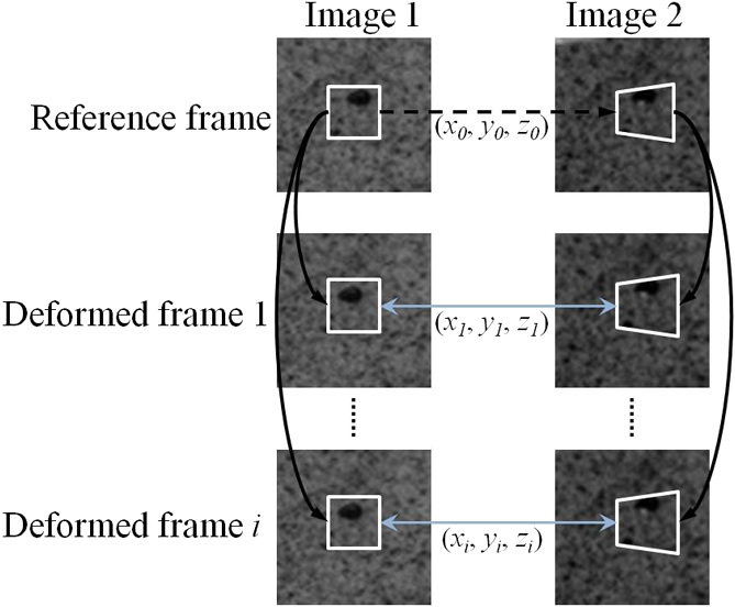 Since the image acquisition process for the two cameras is synchronized, the world coordinates of the target points () at any moment during movement can be estimated based on Eq. (1) after the image coordinates are determined in the two concurrently captured image pairs. The displacement of the target points () during loading can be calculated by subtracting the original world coordinates () from the current world coordinates (). This process continues until the calculations in the two image sequences are completed. 2.2.Experimental Arrangement and CalibrationThe 3-D measurement system consists of two CCD cameras (Baumer TXG 12, Germany) with two standard lenses (Computar M2514-MP2, focal length: 25 mm) and a desktop computer with a Quad-core processer [Inter(R) Core (TM) i5-3470 CPU, 3.20 GHz main frequency, 4 GB RAM].The CCD camera is able to record images with a spatial resolution of at a rate of 32 fps. The system has been calibrated before the measurement. In order to confirm the precision of the measurement system, it was applied to measure the displacement of a metal plate mounted on a 2-D motorized translation stage (KOHZU ZA05A-W1). For convenience, the world coordinate system was defined such that the - and -axes were aligned with the default horizontal and vertical directions, and the normal of the -plane toward the cameras was defined as the -axis. During the experiment, the metal plate was translated 6 mm along the - and -axes with a speed of , respectively. The translation stage stopped for 5 s when an increment of 1 mm was achieved. Four markers were selected by clicking the cursor in the reference image acquired in camera 1, and the corresponding locations of the markers were retrieved in real time. 2.3.Experiments for Biomechanical EvaluationHuman lower legs used in this study were obtained from participating hospitals in Shanghai, China, according to approved protocols issued by the Institutional Review Board of Shanghai University. The samples were frozen at right after extraction, and at 5°C 24 h before the experiments. 2.3.1.Experiments involving foot archThere is a functional relationship between the structure of the arch of the foot and the biomechanics of the lower leg. Since the arch provides an elastic, springy connection between the forefoot and the hind foot, a majority of the forces incurred during weight bearing of the foot can be dissipated before the force reaches the long bones of the leg and thigh. Fallen arch is a postural deformity in which the arches of the foot collapse, which causes the entire sole of the foot to have contact with the ground. In this study, the movement of the arches was evaluated when a vertical load was applied to the foot before and after subtalar joint arthrodesis was conducted. A schematic description of the experimental arrangement is shown in Fig. 3(a). The near end of the tibia was fixed in the upper grip and the crosshead of the test machine was carefully adjusted so that the foot was placed on an aluminum plate. A vertical load was applied to the tibia at a rate of until reaching up to 700 N.11 Fig. 3Schematic diagrams for (a) the experimental setup used for the foot arch measurement and (b) the user-defined coordinate system.  The stereo camera system was used to monitor movement of the arches while loading. In order to measure the invisible talus and metatarsals, surgical pins were firmly inserted into the bones to ensure the white heads of the pins move with the bones. Prior to the experiments, the intrinsic parameters and extrinsic parameters of the stereo camera system were calibrated with a planar checkerboard based on Zhang’s calibration method.16 The world coordinate system was defined with the -plane parallel to the aluminum plate underneath the foot, as indicated in Fig. 3(b). The -axis was defined as the normal to the calibration plate and directed toward the cameras. Images were captured in pairs simultaneously with the stereo imaging system. The 3-D coordinates of the markers relative to talus and metatarsals were determined while loading. 2.3.2.Experiments involving distal tibiofibular syndesmosisThe syndesmosis locates between the triangular fibular notch of the lateral surface of the distal tibia and the medial convex surface of the distal fibula. Damage to normal kinematics of the tibiofibular joint may cause recurrent ankle sprains and even chronic ankle instability.22 Therefore, the distal tibiofibular syndesmosis rupture must be recognized and treated to prevent late complications. In general, operative fixation usually involves the insertion of one or two metallic diastasis screws. The evaluation of the relative movement between tibia and fibulacan reflect the effect of the treatment of distal tibiofibular syndesmosis.23,24 In this experiment, the relative movement between the tibia and fibula were evaluated with the 3-D motion system while the cadaver foot sample was stressed before and after surgery. The experimental arrangement was shown in Fig. 4. The imaging system was calibrated before the test and the corresponding right-hand world coordinate system was defined such that the -plane coincided with the sagittal plane and the -plane coincided with the coronal plane, as shown in Fig. 4. Two surgical pins were inserted into the tibia and fibula, respectively. During the experiments, the foot was subjected to a monotonic rotational torque up to 5 Nm at a speed of 5 deg per min.24 The movements of the four pins were tracked in real time by the proposed DIC technique. 3.ResultsIn conducting the validation experiments, the accuracy of the real-time 3-D-DIC system was evaluated by performing the translation tests. The displacements of the four POIs were averaged in the - and -directions and the corresponding trajectories were displayed in Fig. 5. The displacement trajectories of in-plane and out-of-plane both show good agreement with the preset values. In order to give a quantitative error analysis, the displacements in Fig. 5 at each step were averaged and compared with preset values as listed in Table 1. It was found that the maximum relative error of the in-plane (-axis) displacement was . Similarly, the maximum relative error of the out-of-plane (-axis) was 1.17%. During the measurements, the displacement was output at a rate of 32 Hz from the imaging system. Fig. 5Average motion of the selected markers on the translation stage. (a) in-plane (-direction) and (b) out-of-plane (-direction). 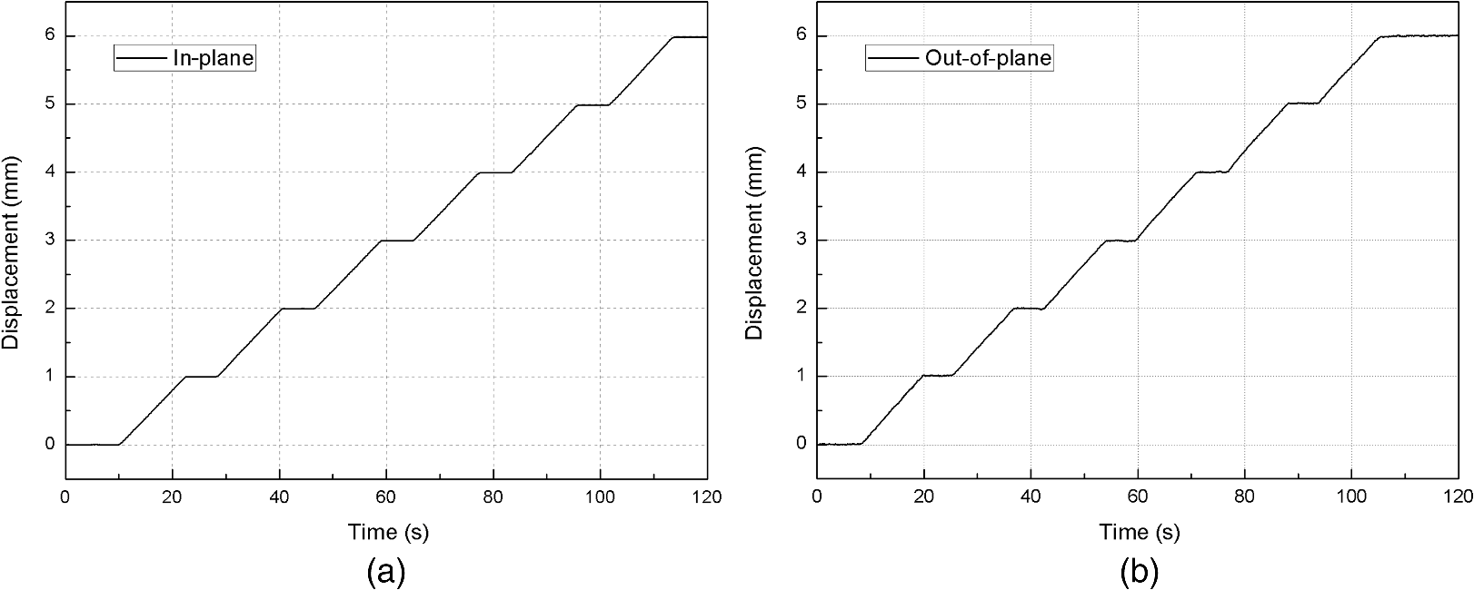 Table 1.Error estimation of the proposed real-time 3-D-DIC system.
In the foot arch experiments, the movement of the five metatarsal bones and the talus were measured as a result of loading before and after treatment. The 3-D displacements were recorded in real time using the computer. Results for the displacement trajectories with loading are shown in Fig. 6. Specifically, the displacement trajectories for the flatfoot deformation in the -, -, and -directions are shown in Figs. 6(a), 6(c), and 6(e), respectively. Similarly, the corresponding displacements in the three directions resulting from loading after the treatment are shown in Figs. 6(b), 6(d), and 6(f), respectively. As ligaments are sheets or bundles of collagen fibers that form a connection between two bones, ligaments act as protective backups for the bones. As subtalar joint arthrodesis involves the fusion of two bones to restore the position of the calcaneus under the talus, which recreates the arch, this fusion can effectively reduce the characteristic “splaying” of the foot in pes planus in the -plane. In the loading situation, the displacements of the foot arches were decreased 5 to 20 mm in all directions after treatment, as shown in Fig. 6. The degree of decrease observed in the - and -directions exceeds that in the -direction. Fig. 6The 3-D displacement trajectories for the foot arches in the individual metatarsals and the talus. Shown individually are the (a) displacement in -direction before treatment, (b) displacement in -direction after treatment, (c) displacement in -direction before treatment, (d) displacement in -direction after treatment, (e) displacement in -direction before treatment, and (f) displacement in -direction after treatment.  In the distal tibiofibular syndesmosis experiments, four markers were monitored and the relative displacement components in the three directions between the tibia and fibula were calculated. The variation of the average relative displacement with increase of torque was evaluated before and after treatment. As shown in Figs. 7(a) and 7(b), after the treatment for the broken distal tibiofibular syndesmosis, 3-D displacements for the measurement were decreased. Specially, the relative displacement decreased significantly in the -direction. This is consistent with the function of the distal tibiofibular syndesmosis, which limits tibia and fibula movement in the coronal plane. 4.DiscussionThe development and application of noncontact methods for precise displacement measurement technique is of substantial interest for engineers.25–28 For biomedical applications, there are often additional technical challenges to overcome that must be considered. This study has illustrated the use of DIC as an optical approach for accurately quantifying the movement of bones in the treatment of pes planus and distal tibiofibular syndesmosis injury. To enable real-time measurement, a fast DIC matching algorithm for 3-D measurement was employed. As shown in Figs. 6 and 7, the measured displacement trajectories of the foot bones in the three directions were presented as a function of loading. Using the displacement data, it is possible to extract key mechanical parameters that help to describe the effectiveness of treatment. For example, the vertical displacements, the relative displacements between bone/bone and bone/joint, the active degree of movement, and so on can be easily accessed. These measures can facilitate greater understanding of the interactions between foot bones and the success of surgical treatment.29–31 In order to keep the specimens intact during the experiments, the soft tissue on top of the bones was not removed. As such, surgical pins were inserted into the bones and were used as the markers for the imaging system. However, as DIC can use the surface texture as the information carrier, it can be applied without markers if the bone can be observed. From this point of view, DIC is still regarded as a noncontact measurement technique. In the traditional approach to DIC, the motion information is extracted by postprocessing the sequential images captured during testing. Clearly that approach was time-consuming, not automated, and also inapplicable for dynamic measurement. This is also a driving force for the development of real-time measurements. In these previous studies, bilinear32 or biquadratic interpolation33 was used in the correlation process to save the computational time and a 10-Hz measurement rate was achieved.32 This could potentially reduce precision in the measurement without the use of bicubic interpolation.3 In contrast, the proposed DIC approach can achieve accurate strain measurement at 60 Hz in a 2-D application.21 In this study, a robust and automatic strategy for real-time measurement of 3-D motion has been presented. As shown in Table 1, a measurement accuracy of in the -direction (in-plane) and 1.17% in the -direction (out-of-plane) was achieved. In the biomechanical experiments, the displacements of six bones in the foot were tracked in real time with a rate of 16 fps. For the proposed method, the tracking speed mainly depends on the camera frame rate, computer performance, and the measured number of points. It is possible to further improve the acquisition rate by upgrading the hardware system. For example, the displacement/strain measurement could be instantly achieved if high-speed cameras were used with greater framing rates. When compared with conventional 3-D-DIC, the proposed method has three distinct advantages. First, the proposed method for 3-D-DIC combined the PSO algorithm with the BBGDS algorithm, which enables rapid convergence to the global optimum integer pixel position. Second, the IC-GN subpixel iteration with bicubic interpolation was introduced, and all correlation matching was performed with the reference frames. That strategy requires that the Hessian matrix is calculated only once in each sequence, which significantly reduces the computational time required without any loss of accuracy in comparison to conventional DIC. Third, the proposed method employed multicore parallel computing technology, which enabled correlation of multiple points to be achieved simultaneously without noninterference. The experiments verified that the proposed 3-D-DIC method is precise and effective for real-time displacement/stain measurement in engineering and biomedical applications. It is important to comment on the potential use of the proposed technique with respect to existing technology. The infrared tracer technique has been widely applied for biomechanical research as a method for noninvasive motion analysis.34–37 This technique employs multiple high-speed or ultra high-speed infrared cameras to monitor reflective markers placed at specific locations for measurement of 3-D trajectories. Although this technique possesses the advantage of nearly instantaneous monitoring speed, it relies on the frame rate of the infrared cameras, which is quite costly. Furthermore, the tracer technique has measurement accuracy that is limited to the millimeter range. An X-ray imaging technique is also an option for determining 3-D motion in biomedical applications,38 whereas the protection for radiation makes it difficult in common laboratory studies. In comparison, the proposed real-time 3-D-DIC technique could be performed using affordable CCD cameras for real-time motion measurement and has an accuracy within the submicrometer range. The proposed technique can also achieve a high-tracking speed if high-speed CCD cameras and a multicore computer are employed. 5.ConclusionA real-time 3-D-DIC method for dynamic displacement/stain measurement has been described and applied in this paper. The proposed system is capable of measuring the displacement of six points simultaneously with a monitoring speed of about 16 fps. The approach utilizes a combination of a fast 2-D-DIC search strategy with an immediate 3-D matching scheme. The accuracy and effectiveness of the presented technique were proven through a translation test using a motorized precision translation stage and biomechanics applications involving the motion of foot bones. From the experimental results obtained, it can be concluded that the established system can offer a solution for dynamic motion measurement in 3-D space. It could facilitate performing fatigue/cyclic tests on biological materials and facilitate achieving a better understanding of the mechanical behavior of biological materials. The system has potential for improvements in displacement/strain measuring speed if the CCD cameras and the computer used possess higher speeds than the current ones. AcknowledgmentsThe authors would like to thank the National Natural Science Foundation of China Nos. 11372173 and 11672347. Technical support from the Instrumental Analysis and Research Center at Shanghai University is also acknowledged. ReferencesD. Zhang and X. Zhang,
“Data analysis system for film,”
Opt. Eng., 37
(11), 2914
–2917
(1998). http://dx.doi.org/10.1117/1.601878 Google Scholar
J. C. Passieux et al.,
“A digital image correlation method for tracking planar motions of rigid spheres: application to medium velocity impacts,”
Exp. Mech., 54
(8), 1453
–1466
(2014). http://dx.doi.org/10.1007/s11340-014-9930-y EXMCAZ 0014-4851 Google Scholar
H. W. Schreier, J. R. Braasch and M. A. Sutton,
“Systematic errors in digital image correlation caused by intensity interpolation,”
Opt. Eng., 39
(11), 2915
–2921
(2000). http://dx.doi.org/10.1117/1.1314593 Google Scholar
D. Zhang, C. D. Eggleton and D. Arola,
“Evaluating the mechanical behavior of the arterial tissue using digital image correlation,”
Exp. Mech., 42
(4), 409
–416
(2002). http://dx.doi.org/10.1007/BF02412146 EXMCAZ 0014-4851 Google Scholar
M. S. Thompson et al.,
“Digital image correlation: a technique for determining local mechanical conditions within early bone callus,”
Med. Eng. Phys., 29
(7), 820
–823
(2007). http://dx.doi.org/10.1016/j.medengphy.2006.08.012 MEPHEO 1350-4533 Google Scholar
D. Zhang, D. Arola and M. Luo,
“Analysis of the mechanical behavior of bovine hoof horn using digital image correlation,”
Chin. J. Biomed. Eng., 15
(3), 103
–112
(2006). ZSYXEI 0258-8021 Google Scholar
M. A. Sutton et al.,
“Strain field measurements on mouse carotid arteries using microscopic three-dimensional digital image correlation,”
J. Biomed. Mater. Res. A., 84A
(2), 178
–190
(2008). http://dx.doi.org/10.1002/(ISSN)1552-4965 Google Scholar
D. T. Yang, D. Zhang and D. Arola,
“Fatigue of the bone/cement interface and loosening of total joint replacements,”
Int. J. Fatigue, 32
(10), 1639
–1649
(2010). http://dx.doi.org/10.1016/j.ijfatigue.2010.03.005 IJFADB 0142-1123 Google Scholar
D. Zhang and D. D. Arola,
“Applications of digital image correlation to biological tissues,”
J. Biomed. Opt., 9
(4), 691
–699
(2004). http://dx.doi.org/10.1117/1.1753270 JBOPFO 1083-3668 Google Scholar
P. Srinivasan et al.,
“Experimental and computational micromechanics at the tibial cement-trabeculae interface,”
J. Biomech., 49
(9), 1641
–1648
(2016). http://dx.doi.org/10.1016/j.jbiomech.2016.03.054 JBMCB5 0021-9290 Google Scholar
H. Niki et al.,
“The effect of posterior tibial tendon dysfunction on hindfoot kinematics,”
Foot Ankle Int., 22
(4), 292
–300
(2001). http://dx.doi.org/10.1177/107110070102200404 FAINE4 Google Scholar
S. P. Soin et al.,
“Suture-button versus screw fixation in a syndesmosis rupture model: a biomechanical comparison,”
Foot Ankle Int., 30
(4), 346
–352
(2009). http://dx.doi.org/10.3113/FAI.2009.0346 FAINE4 Google Scholar
T. Huber, W. Schmoelz and A. Bölderl,
“Motion of the fibula relative to the tibia and its alterations with syndesmosis screws: a cadaver study,”
Foot Ankle Surg., 18
(3), 203
–209
(2012). http://dx.doi.org/10.1016/j.fas.2011.11.003 Google Scholar
F. Li, J. Liu and K. Yue,
“Exact analytical solution to three-dimensional phase change heat transfer problems in biological tissues subject to freezing,”
Appl. Math. Mech.-Engl. Ed., 30 63
–72
(2009). http://dx.doi.org/10.1007/s10483-009-0107-x Google Scholar
E. M. Mikhail, J. S. Bethel and J. C. McGlone, Introduction to Modern Photogrammetry, Wiley, New York
(2001). Google Scholar
Z. Zhang,
“A flexible new technique for camera calibration,”
IEEE Trans. Pattern Anal. Mach. Intell., 22
(11), 1330
–1334
(2000). http://dx.doi.org/10.1109/34.888718 ITPIDJ 0162-8828 Google Scholar
J. Kennedy and R. Eberhart,
“Particle swarm optimization,”
in Proc. of IEEE Int. Conf. on Neural Networks,
1942
–1948
(1995). Google Scholar
Y. Wang, B. Zhang and Y. Chen,
“Robust airfoil optimization based on improved particle swarm optimization method,”
Appl. Math. Mech.-Engl. Ed., 32 1245
–1254
(2011). http://dx.doi.org/10.1007/s10483-011-1497-x Google Scholar
B. Pan, K. Li and W. Tong,
“Fast, robust and accurate digital image correlation calculation without redundant computations,”
Exp. Mech., 53
(7), 1277
–1289
(2013). http://dx.doi.org/10.1007/s11340-013-9717-6 EXMCAZ 0014-4851 Google Scholar
L. K. Liu and E. Feig,
“A block-based gradient descent search algorithm for block motion estimation in video coding,”
IEEE Trans. Circuits Syst. Video Technol., 6
(4), 419
–422
(1996). http://dx.doi.org/10.1109/76.510936 ITCTEM 1051-8215 Google Scholar
R. Wu et al.,
“Real-Time digital image correlation for dynamic strain measurement,”
Exp. Mech., 56
(5), 833
–843
(2016). http://dx.doi.org/10.1007/s11340-016-0133-6 EXMCAZ 0014-4851 Google Scholar
A. Teramoto et al.,
“Three-dimensional analysis of ankle instability after tibiofibular syndesmosis injuries: a biomechanical experimental study,”
Am. J. Sports Med., 36
(2), 348
–352
(2008). http://dx.doi.org/10.1177/0363546507308235 Google Scholar
R. Dattani et al.,
“Injuries to the tibiofibular syndesmosis,”
Bone Jt. J., 90
(4), 405
–410
(2008). http://dx.doi.org/10.1302/0301-620X.90B4.19750 Google Scholar
A. den Daas et al.,
“Flexible stabilization of the distal tibiofibular syndesmosis: clinical and biomechanical considerations: a review of the literature,”
Strategies Trauma Limb Reconstr., 7
(3), 123
–129
(2012). http://dx.doi.org/10.1007/s11751-012-0147-2 Google Scholar
S. Zhang et al.,
“Characterization of the strain-life fatigue properties of thin sheet metal using an optical extensometer,”
Opt. Lasers Eng., 60 44
–48
(2014). http://dx.doi.org/10.1016/j.optlaseng.2014.03.011 OLENDN 0143-8166 Google Scholar
F. J. Le et al.,
“A 3d displacement control by digital image correlation for the multiaxial testing of materials with a Stewart platform,”
Exp. Mech., 54
(5), 817
–828
(2014). http://dx.doi.org/10.1007/s11340-013-9837-z EXMCAZ 0014-4851 Google Scholar
J. T. Deland et al.,
“Posterior tibial tendon insufficiency: which ligaments are involved?,”
Foot Ankle Int., 26
(6), 427
–435
(2005). http://dx.doi.org/10.1177/107110070502600601 FAINE4 Google Scholar
R. R. Wang et al.,
“Importance of aging to dehydration shrinkage of human dentin,”
Appl. Math. Mech.-Engl. Ed., 33
(3), 333
–344
(2012). http://dx.doi.org/10.1007/s10483-012-1553-8 Google Scholar
W. H. Seitz et al.,
“Repair of the tibiofibular syndesmosis with a flexible implant,”
J. Orthop. Trauma, 5
(1), 78
–82
(1991). http://dx.doi.org/10.1097/00005131-199103000-00014 JORTE5 0890-5339 Google Scholar
J. E. Johnson et al.,
“Subtalar arthrodesis with flexor digitorum longus transfer and spring ligament repair for treatment of posterior tibial tendon insufficiency,”
Foot Ankle Int., 21
(9), 722
–729
(2000). http://dx.doi.org/10.1177/107110070002100902 FAINE4 Google Scholar
J. Tome et al.,
“Comparison of foot kinematics between subjects with posterior tibialis tendon dysfunction and healthy controls,”
J. Orthop. Sports Phys. Ther., 36
(9), 635
–644
(2006). http://dx.doi.org/10.2519/jospt.2006.2293 Google Scholar
G. Tao and Z. Xia,
“A non-contact real-time strain measurement and control system for multiaxial cyclic/fatigue tests of polymer materials by digital image correlation method,”
Polym. Test., 24
(7), 844
–855
(2005). http://dx.doi.org/10.1016/j.polymertesting.2005.06.013 POTEDZ 0142-9418 Google Scholar
Y. H. Huang et al.,
“Real-time monitoring of clamping force of a bolted joint by use of automatic digital image correlation,”
Opt. Laser Technol., 41
(4), 408
–414
(2009). http://dx.doi.org/10.1016/j.optlastec.2008.08.010 OLTCAS 0030-3992 Google Scholar
M. P. Kadaba, H. K. Ramakrishnan and M. E. Wootten,
“Measurement of lower extremity kinematics during level walking,”
J. Orthop. Res., 8
(3), 383
–392
(1990). http://dx.doi.org/10.1002/(ISSN)1554-527X JOREDR 0736-0266 Google Scholar
A. Arndt et al.,
“Intrinsic foot kinematics measured in vivo during the stance phase of slow running,”
J. Biomech., 40
(12), 2672
–2678
(2007). http://dx.doi.org/10.1016/j.jbiomech.2006.12.009 JBMCB5 0021-9290 Google Scholar
C. Nester et al.,
“Foot kinematics during walking measured using bone and surface mounted markers,”
J. Biomech., 40
(15), 3412
–3423
(2007). http://dx.doi.org/10.1016/j.jbiomech.2007.05.019 JBMCB5 0021-9290 Google Scholar
A. R. Altman and I. S. Davis,
“A kinematic method for footstrike pattern detection in barefoot and shod runners,”
Gait Posture, 35
(2), 298
–300
(2012). http://dx.doi.org/10.1016/j.gaitpost.2011.09.104 Google Scholar
C. Wang et al.,
“Three-dimensional motions of distal syndesmosis during walking,”
J. Orthop. Surg. Res., 10
(1), 1
–8
(2015). http://dx.doi.org/10.1186/s13018-014-0138-8 Google Scholar
BiographyRong Wu received his BS degree in measurement and control technology and instruments from East China Jiaotong University, China, and his MS degree in solid mechanics from Shanghai University. Currently, he is pursuing his PhD with research interests including digital image correlation, 3-D stereo measurement, and the applications in engineering and biomedical applications. Hua Wu received his MS degree in clinical medicine from Shanghai Sixth People’s Hospital, Shanghai, China. He is currently an orthopedist at the Second People’s Hospital of Foshan, China. He has been engaged in clinical work in orthopedics for 6 years. Dwayne Arola is currently a professor of material science and engineering (MSE) at the University of Washington. He also holds joint appointments in mechanical engineering, oral health science, and restorative dentistry. His research involves studies concerning the microstructure and mechanical behavior of dental, engineering, and natural materials. His interests are presently focused on the fatigue and fracture behavior of structural materials and understanding the influence of environmental challenges and aging on these aspects of durability. Dongsheng Zhang received his PhD at Tianjin University, Tianjin, China, in 1993. He is currently a professor in the Department of Mechanics, Shanghai University, Shanghai, China. His research involves research and development of the advanced optical measurement methods including interferometry and digital image correlation. He is also interested in studying the mechanical behaviors of biological hard tissues such as enamel, dentin, and bone with change in microstructure. |
|||||||||||||||||||||||||||||||||||