|
|
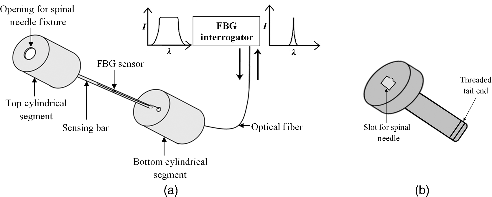
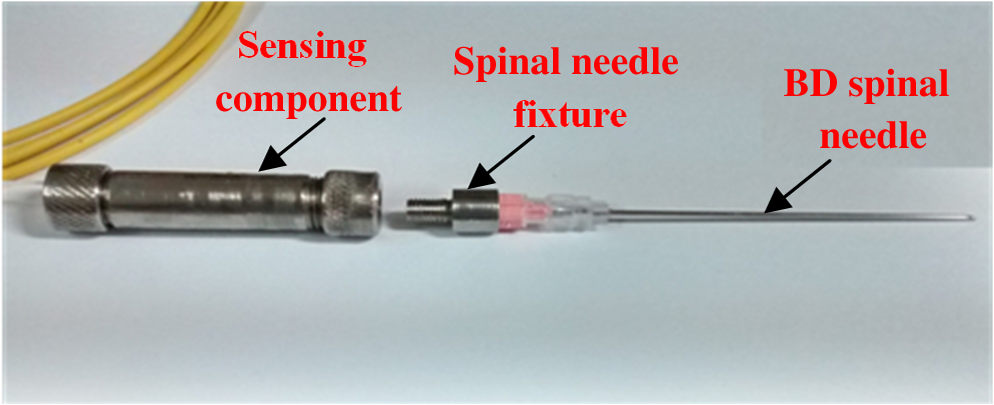
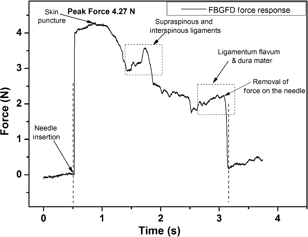
1.IntroductionClinical practices mostly involve needle insertion procedures that require puncturing of skin tissues. A skilled medical practitioner penetrates the needle through different tissue layers in order to reach to the target location for treatment, optimizing the traverse path of the needle by virtue of his own sensory feel of the resistance force. Tissue properties for different individuals vary in terms of thickness, stiffness, and so on. In procedures such as biopsy and epidural anesthesia, needle positioning accuracy is highly essential. Study of biomedical interaction of a surgical needle for invasive diagnosis through tissue layers is an essential aspect for surgical applications. Critical cases of medical errors, such as accidental puncturing of vital organs during surgeries, committed by trainee surgeons and staff, need to be avoided. These can be prevented with a better understanding of needle interaction with tissue assisted by essential surgical skills training with advanced technical tools.1 Also, it is imperative to know the real-time positioning of the spinal needle during the lumbar puncture (LP) procedure which is utilized for several diagnostic and therapeutic medical practices involving collection of cerebrospinal fluid (CSF)2 or to reduce increased intracranial pressure. The most common issue persisting in this methodology is post-dural-puncture headache.3 Earlier studies carried out on force feedback monitoring of needle insertion4–7 mainly focus on applications involving robotic surgery or minimally invasive surgeries using haptic feedback mechanism.8–15 Magill et al. demonstrated a mechanical actuator-based technique that simulates a haptic experience similar to penetrating tissue with a needle using brushless motors supported force feedback system.16 A direct methodology of needle insertion force measurement has been illustrated for gelatine analogs, a bevel-tip needle mounted on a digital force gauge that provides the needle insertion forces used to model the consistency of the tissues in the lumbar region of the back.9 Another prototype for haptic force feedback monitoring on a human mannequin torso using a hardware- and software-based haptic device and simulation methodology was demonstrated by Gorman et al.2 A few other epidural hardware- and software-based simulators for force feedback monitoring are also reported.3,17–20 These techniques employ bulky sensors and complex system application for force estimation on spinal needle insertion. However, the above-mentioned methodologies do not provide a practical hand-held solution for force monitoring during spinal needle insertion. Recently, FBG sensors are greatly in use for applications in the biomedical field due to their numerous advantages such as small size, chemical inertness, high sensitivity, ultrafast response, electrically passive operation, insensitivity to radio frequency, and immunity to electromagnetic interference.21–24 In their basic form, FBG sensors are sensitive to strain and temperature; with employment of various transduction techniques they can be used to sense a variety of parameters such as pressure, vibration, force, and flow.25–27 The present study describes a methodology of spinal needle force monitoring system during LP using fiber Bragg grating force device (FBGFD). The developed FBGFD transduces the spinal needle interaction forces with tissue regions into strain variations that are acquired by the FBG sensor. A major advantage of using an FBG sensor in FBGFD is its compact dimension that fits in perfectly making it a rugged and portable device. The basic idea behind the design of FBGFD is to dynamically monitor the force experienced by a spinal needle during LP by which the region of penetration of the spinal needle may be evaluated. The prominent difficulty faced in force monitoring on the spinal needle is its bending effect. The major advantage of the developed FBGFD is its ability to measure the force experienced on the spinal needle by the elimination of bending effect. 2.Materials and Methods2.1.Fiber Bragg Grating SensorAn FBG sensor consists of a periodic modulation of the refractive index of the core of a single-mode photosensitive optical fiber along its axis. When a broadband light is launched into an optical fiber inscribed with FBG, one particular wavelength that satisfies the Bragg condition, given by Eq. (1), is reflected back and the remaining wavelengths are transmitted through the optical fiber.28 The reflected Bragg wavelength from the FBG is given as Here, the Bragg resonance wavelength is the free space center wavelength of the input light that will be backreflected from the Bragg grating. is the effective refractive index of the fiber and Λ is the grating periodicity. In the present work, phase mask technique is29–31 used for photoinscription of gratings32,33 by exposing the core of a photosensitive, germano-silicate fiber through an interference pattern created using KrF excimer UV laser of wavelength 248 nm (BraggStar industrial, TUI laser). FBG sensors with a gauge length of 3 mm are fabricated. The strain effect on an FBG sensor is expressed as where and are components of the strain-optic tensor, is the Poisson’s ratio, and is the axial strain change.34 The strain sensitivity of an FBG inscribed in a germania-doped silica fiber is .35As the temperature variations may also cause a shift in the Bragg wavelength, it is imperative to compensate for temperature variations (if any) while using the FBG sensor for strain measurements. In this work, experiments carried out are within a short duration of time and in controlled environmental conditions where temperature change was negligibly small thus the temperature effect on the FBG sensor is ignored. 2.2.Design and Fabrication of Fiber Bragg Grating Force DeviceThe FBGFD comprises two cylindrical segments made of stainless steel (top and bottom) of diameter 10 mm and length 15 mm each, joined together by means of a sensing bar of length 40 mm and diameter 0.9 mm. The FBG sensor is positioned on the surface of the sensing bar such that the sensor grating length of 3 mm lies at the center along the length of the sensing bar. The FBG sensor is glued using industrial adhesive (Loctite 420) and allowed to cure for 30 min. This assembly constitutes to form the sensing component of FBGFD as shown in Fig. 1(a). An opening on the top cylindrical segment is provided with threads in order to attach the spinal needle fixture. A spinal needle fixture with a head part of diameter 10 mm and tail part of diameter 4 mm is designed for holding the spinal needle. The spinal needle fixture facilitates a groove that is made to house the spinal needle with a depth of holding of 8 mm as shown in Fig. 1(b). The tail end of the spinal needle fixture can be screwed to the sensing component by the means of threads provided on it. The assembly of the sensing component is housed inside a 70-mm-long hollow casing of inner diameter 10 mm and outer diameter 12 mm. The inner diameter of the hollow tube is maintained such that the sensing component is housed perfectly inside it. This is done in order to restrict any lateral movement of the sensing component allowing it to move only axially. The length of the hollow tube is maintained so as to match the full longitudinal dimension of the sensing component. Both ends of the tube are closed using threaded caps provided with openings for the spinal needle fixture to attach on one side and for routing the optical fiber connecting FBG sensor on the other side. Thus, this mechanism ensures only 1-deg of freedom for the movement of the sensing component, i.e., only axial movement inside the hollow tube. Upon application of any force on the spinal needle mounted over the spinal needle fixture which is attached to the sensing component, the compressive force will be axially translated via the spinal needle fixture to the sensing component which further induces a compressive strain on the sensing bar. The FBG sensor acquires the compressive strain in terms of shift in Bragg wavelength. The lateral movement of the sensing component due to the spinal needle bending is negated by virtue of hollow tube walls. The reflected Bragg wavelength is acquired by means of micron optics interrogator SM130-700 which has a resolution of 1-pm wavelength shift. The complete system of the spinal needle fixture attached to the sensing component bonded with the FBG sensor housed inside a hollow casing constitutes to become the FBGFD. This is used with a mounted spinal needle for real-time dynamic monitoring of force acting on a spinal needle as shown in Fig. 2. Thus utilizing FBGFD force experienced by the spinal needle during LP procedure, different tissue regions of varying stiffness penetrated can be dynamically monitored negating the effect of spinal needle bending. All components of FBGFD are made of stainless steel material as shown in Fig. 3. The FBGFD is made lightweight, compact, and rugged facilitating its easy usage manually by the medical practitioner. 3.Experimental Analysis3.1.Calibration TestThe FBGFD developed has been calibrated using a Mecmesin’s micro-universal testing machine () for a range of applied force. The FBGFD is allowed to stand upright on a fixture for compressive force measurement (Fig. 4). The spinal needle fixture is put in direct contact with the UTM force device. The UTM is programmed to travel vertically at a rate of with application of force on FBGFD from the spinal needle fixture end. The Bragg wavelength shift of the FBG sensor of FBGFD due to progressive application of force from UTM is continuously monitored and recorded. Figure 5(a) shows the comparison of force monitored by UTM and the corresponding strain from the FBG sensor. It can be deduced that both FBG response and UTM response are in good agreement with each other in the investigated ranges of force. Further, for the range of forces applied by UTM, the strain experienced by FBGFD is obtained from the shift in the Bragg wavelength of the FBG sensor, using the strain sensitivity of .35 The shift in wavelength and the strain experienced by the FBGFD, with the application of UTM force, exhibits a linear response which is demonstrated by the correlation coefficient of 0.99 obtained as shown in Fig. 5(b). For a maximum applied force of 19.3 N, the compressive strain in the FBGFD is found to be , indicating an FBGFD sensitivity of . The force sensitivity of FBGFD in terms of wavelength shift is obtained as . The FBGFD sensitivity is dependent upon the thickness of the sensing bar. The sensitivity of the device reduces as the thickness of the sensing bar increases. The device has a fine resolution of 0.021-N force measurement. 3.2.Experimental MethodologyAn attempt is made to quantify the forces experienced by a spinal needle while it is introduced into the subarachnoid space of the Thoraco-lumbar spine. The experiment is carried out on a specially embalmed human cadaver specimen that has retained the organoleptic properties and gives the feel of live tissue while handling. The Cadaver specimen has been positioned in the right lateral position and the interspinous spaces have been palpated at the Thoraco-lumbar junction and the lumbar spine. The spinal needle with Quincke type point from Becton, Dickinson and Company (BD) of 18GA 3.50IN () is mounted to the FBGFD and introduced into the subarachnoid space as shown in Fig. 6(a). The dynamic force variations experienced by the spinal needle due to the resistance offered by various tissue layers are recorded from FBGFD during the spinal needle traversal. Multiple attempts of puncturing with the spinal needle are made with 18 gauge spinal needles at multiple levels from T12-L1 to L4-L5. As the spinal needle penetrates through different tissue layers, the force experienced by it varies with the resistance due to tissue stiffness or in other words the force required to penetrate through a tissue layer depends on its stiffness. When the spinal needle traverses from regions of tissues with lower stiffness to higher stiffness, the tissue resistance increases which generates higher compressive force on the spinal needle recorded by the FBGFD and vice versa. The repeated tests and trials have been conducted with spinal needle insertion in different directions and pace in order to monitor the varying forces on the spinal needle. 4.ResultsThe validation experiments are carried out by an experienced medical practitioner by progressive insertion of the spinal needle, while performing an LP procedure on a human cadaver specimen; during the procedure, the dynamic force variations experienced by the spinal needle is recorded from the FBGFD. The dynamic force variations over the spinal needle are converted to strain variation and continuously recorded from the FBGFD during the LP procedure. The varying force experienced by the spinal needle upon full length traversal through skin to epidural space puncturing various tissue layers during LP is shown in Fig. 7. The force response from the FBGFD is quantified with respect to time during the performance of the LP. Before the insertion of the spinal needle into the lumbar area, there is no force experienced on the needle as observed by the 0-N force response. Compressive force monitored during spinal needle traversal inside the specimen is marked with the dotted lines. The spinal needle insertion initiates with the encounter of skin opposing its penetration with a resistive force creating a compressive force on it. A peak force of 4.27 N is recorded at which skin punctures allowing the needle to enter the cadaver specimen, as observed in Fig. 7. With continued traversal of the spinal needle, the force experienced on it decreases due to the lesser resistance offered by the tissue layers beneath the skin layer. Further, the spinal needle at the supaspinous and interspinous ligament regions experiences higher resistance and hence a force of 3.5 N is recorded during piercing this region. The sudden decrease in the force on the spinal needle as observed in Fig. 7 indicates the specific tissue being punctured and the spinal needle’s progression into the next tissue layer. As the spinal needle traverses further the resistance offered by the tissue layers are lower when compared to the initial tissue layers beneath the skin. This shows that the tissue layers beneath the skin are stiffer than the tissue layers in the supaspinous and interspinous ligament regions. A force of 2.2 N is recorded on the spinal needle which represents the piercing of the ligamentum flavum and dura mater and the entrance of the spinal needle into the epidural space, as observed from Fig. 7. Upon reaching the epidural space, the resistance offered to the spinal needle drastically decreases, which is also sensed by the medical practitioner who is performing the procedure. As the spinal needle enters the epidural space, the insertion process is stopped which is observed as the force on the spinal needle returning toward the zero baseline, depicting the end of the LP procedure. Direction of spinal needle insertion and its traversal is a key factor during the LP test in order to find an optimized pathway of its traversal avoiding encounter of unwanted bones, organs, or tissues, minimizing accidental injuries. Another LP test performed on the same cadaver specimen, from different directions is depicted in Fig. 8. It is observed that the force on the spinal needle increases with the traversal after the puncturing of the skin layer. The force on the spinal needle increases to 11.45 N, which is due to the bone encountered in the traversal path of the spinal needle. The bone does not allow the spinal needle to pierce through and hence a high opposing force is observed as indicated by trial 1 in Fig. 8. As no further insertion of the spinal needle is possible, the medical practitioner had to retrace the needle and begin the procedure again in a different direction. During the reinsertion of the spinal needle shown as trial 2 in Fig. 8, the application of force for skin puncturing is carried out at a slower rate. The spinal needle punctures the skin with a force of 4.31 N which is in good agreement with the earlier test performed. Also, the penetration of regions of supaspinous and interspinous ligament along with ligamentum flavum and dura mater by the spinal needle is observed with a force of 2.2 and 0.8 N, respectively. The resistance offered by the tissue regions to the traversal of the spinal needle also depends on the direction of the spinal needle insertion. Therefore, the forces required to penetrate these regions in the opted pathway of trial 2 are observed to be less than the earlier tests performed. Upon reaching the epidural space, the insertion procedure is halted and the force on the spinal needle returns to the baseline state. The undesirable bone encounter can be avoided upon comprehending a high spinal needle force on real time using FBGFD. 5.DiscussionThese obtained results proved the efficacy of the developed FBGFD’s employment as a force feedback mechanism during the LP tests. The FBGFD responds only to compressive force acting on the spinal needle negating any bending effect along with any vibrations generated during the insertion procedure. Also, chances of the sensor getting damaged are greatly reduced because of the rugged and enclosed structure of FBGFD. The FBG sensor is present inside the FBGFD and is not in direct contact with the specimen body or the surgeon performing the LP procedure. Thus, the FBG sensor is not affected by any temperature change; hence no temperature compensation is required. This demonstrates its usability in clinical applications for real-time force monitoring during spinal needle insertion procedures. It is important to note that the FBGFD is devised providing the possibility for sterilization of the detachable spinal needle fixture. The FBGFD can be reused for LP tests with the replacement of the spinal needle. The continuous feedback force monitoring of the spinal needle traversal helps in correctly determining the regions penetrated and also preventing any unwanted further penetration of the spinal needle upon reaching the region looked-for. As the spinal needle reaches the desired location in the epidural space, the FBGFD can be detached releasing the spinal needle. Thus, only the spinal needle is left, from which a sample of CSF may be extracted from the epidural space for testing and for any further procedures required in surgery. Furthermore, FBGFD with its feedback force monitoring capability may greatly aid in providing a safe method for trainees to perform the LP procedure, knowing the region of spinal needle penetration. 6.ConclusionA FBGFD, based on an FBG sensor, for the real-time dynamic spinal needle force monitoring, having a resolution of 0.021 N, has been presented in this work. Design and development of the FBGFD and its validation in an LP test are detailed. The FBGFD has an ability to mount spinal needles of various gauge size for carrying out LP procedures. The resistances experienced due to various tissue regions of varying stiffness encountered while inserting the spinal needle is axially translated into strain which is acquired by the FBG sensor. The resultant compressive force acting on the spinal needle is evaluated which in turn is the coarse indication of the region of tissue layer being pierced by the spinal needle. Various layers encountered by an 18-GA spinal needle during experiments performed on a human cadaver specimen have been illustrated in the form of varying forces for the spinal needle traversal. The present device can be potentially used to provide real-time tactile feedback for a successful LP avoiding any severe surgical accident. The FBGFD has an assembly of parts that can be repeatedly utilized. Further, the present device can be used to examine the forces experienced by different gauges of spinal needles using FBGFD, during LP tests. The authors declare that there is no conflict of interest. ReferencesB. Tang, G. B. Hanna and A. Cuschieri,
“Analysis of errors enacted by surgical trainees during skills training courses,”
Surgery, 138 14
–20
(2005). http://dx.doi.org/10.1016/j.surg.2005.02.014 SURGAZ 0039-6060 Google Scholar
P. Gorman et al.,
“A prototype haptic lumbar puncture simulator,”
Medicine Meets Virtual Reality, 106
–109 IOS Press, Amsterdam
(2000). Google Scholar
A. P. Daykin and R. J. Bacon,
“An epidural injection simulator,”
Anaesthesia, 45 235
–236
(1990). http://dx.doi.org/10.1111/ana.1990.45.issue-3 Google Scholar
A. M. Okamura, C. Simone and M. D. O’Leary,
“Force modeling for needle insertion into soft tissue,”
IEEE Trans. Biomed. Eng., 51
(10), 1707
–1716
(2004). http://dx.doi.org/10.1109/TBME.2004.831542 Google Scholar
J. Z. Moore et al.,
“Hollow needle tissue insertion force model,”
CIRP Ann. Manuf. Technol., 60 157
–160
(2011). http://dx.doi.org/10.1016/j.cirp.2011.03.101 Google Scholar
L. L. H. Holton,
“Force models for needle insertion created from measured needle puncture data,”
Medicine Meets Virtual Reality, 180
–186 IOP Press, Amsterdam
(2001). Google Scholar
H. Kataoka et al.,
“Measurement of the tip and friction force acting on a needle during penetration,”
MICCAI 2488, 216
–223 Springer-Verlag, London
(2002). Google Scholar
N. Vaughan et al.,
“A review of epidural simulators: where are we today?,”
Med. Eng. Phys., 35 1235
–1250
(2013). http://dx.doi.org/10.1016/j.medengphy.2013.03.003 Google Scholar
K. W. Ng et al.,
“Needle insertion forces studies for optimal surgical modeling,”
Int. J. Biosci., Biochem. Bioinf., 3 187
–191
(2013). http://dx.doi.org/10.7763/IJBBB.2013.V3.193 Google Scholar
B. Gillespie and L. B. Rosenberg,
“Design of high-fidelity haptic display for one-dimensional force reflection applications,”
Proc. SPIE, 2351 44
–54
(1994). http://dx.doi.org/10.1117/12.197331 Google Scholar
N. Abolhassani, R. Patel and M. Moallem,
“Needle insertion into soft tissue: a survey,”
Med. Eng. Phys., 29 413
–431
(2007). http://dx.doi.org/10.1016/j.medengphy.2006.07.003 Google Scholar
D. S. Kwon et al.,
“Realistic force reflection in a spine biopsy simulator,”
in Proc. IEEE Int. Conf. on Robotics & Automation,
1358
–1363
(2001). http://dx.doi.org/10.1109/ROBOT.2001.932799 Google Scholar
M. Farber, J. Heller and H. Handels,
“Simulation and training of lumbar punctures using haptic volume rendering and a 6DOF haptic device,”
Proc. SPIE, 6509 65090F
(2007). http://dx.doi.org/10.1117/12.709253 Google Scholar
G. Tholey, J. P. Desai and A. E. Castellanos,
“Force feedback plays a significant role in minimally invasive surgery—results and analysis,”
Ann. Surg., 241 102
–109
(2005). http://dx.doi.org/10.1097/01.sla.0000149301.60553.1e Google Scholar
A. R. Lanfranco et al.,
“Robotic surgery: a current perspective,”
Ann. Surg., 239 14
–21
(2004). http://dx.doi.org/10.1097/01.sla.0000103020.19595.7d Google Scholar
J. C. Magill et al.,
“A novel actuator for simulation of epidural anesthesia and other needle insertion procedures,”
J. Soc. Simul. Healthcare, 5
(3), 179
–184
(2010). http://dx.doi.org/10.1097/SIH.0b013e3181ce761a Google Scholar
P. N. Brett et al.,
“Automatic surgical tools for penetrating flexible tissues,”
IEEE Eng. Med. Biol. Mag., 14
(3), 264
–270
(1995). http://dx.doi.org/10.1109/51.391778 Google Scholar
M. Bostrom, S. K. Singh and C. W. Wiley,
“Design of an interactive lumbar puncture simulator with tactile feedback,”
in IEEE Virtual Reality Annual International Symp.,
280
–286
(1993). http://dx.doi.org/10.1109/VRAIS.1993.380768 Google Scholar
T. Dang, T. M. Annaswamy, M. A. Srinivasan,
“Development and evaluation of an epidural injection simulator with force feedback for medical training,”
Medicine Meets Virtual Reality, 81 97
–102 IOP Press, Amsterdam
(2001). Google Scholar
S. P. DiMaio and S. E. Salcudean,
“Needle insertion modeling and simulation,”
IEEE Trans. Robot. Automat., 19 864
–875
(2003). http://dx.doi.org/10.1109/TRA.2003.817044 IRAUEZ 1042-296X Google Scholar
S. Umesh and S. Asokan,
“A brief overview of the recent bio-medical applications of fiber Bragg grating sensors,”
J. Indian Inst. Sci., 94
(3), 319
–328
(2014). JIISAD 0970-4140 Google Scholar
A. Mendez,
“Fiber Bragg grating sensors for biomedical applications,”
in OSA Photonics and Fiber Technology Congress,
(2016). Google Scholar
E. Al-Fakih, N. A. A. Osman and F. R. M. Adikan,
“The use fiber Bragg grating sensors in biomechanics and rehabilitation applications: the state-of-the-art and ongoing research topics,”
Sensors, 12 12890
–12926
(2012). http://dx.doi.org/10.3390/s121012890 SNSRES 0746-9462 Google Scholar
P. Roriz et al.,
“Review of fiber-optic pressure sensors for biomedical and biomechanical applications,”
J. Biomed. Opt., 18
(5), 050903
(2013). http://dx.doi.org/10.1117/1.JBO.18.5.050903 Google Scholar
Q. Yu et al.,
“Study on optical fiber Bragg grating temperature sensors for human body temperature monitoring,”
in Proc. Symp. Photonics and Optoelectronics (SOPO),
1
–4
(2012). Google Scholar
J. Paul, L. Zhao and B. K. A. Ngoi,
“Fiber optic sensor for handgrip-strength monitoring: conception and design,”
Appl. Opt., 44
(18), 3696
–3704
(2005). http://dx.doi.org/10.1364/AO.44.003696 APOPAI 0003-6935 Google Scholar
D. H. C. Wang et al.,
“An optical fiber Bragg grating force sensor for monitoring sub-bandage pressure during compression therapy,”
Opt. Express, 21
(17), 19799
–19807
(2013). http://dx.doi.org/10.1364/OE.21.019799 OPEXFF 1094-4087 Google Scholar
A. Othonos,
“Fiber Bragg gratings,”
Rev. Sci. Instrum., 68 4309
–4341
(1997). http://dx.doi.org/10.1063/1.1148392 RSINAK 0034-6748 Google Scholar
K. O. Hill et al.,
“Bragg gratings fabricated in monomode photosensitive optical fibers by UV exposure through a phase mask,”
Appl. Phys. Lett., 62 1035
–1037
(1993). http://dx.doi.org/10.1063/1.108786 APPLAB 0003-6951 Google Scholar
A. Othonos and K. Kalli, Fiber Bragg Gratings Fundamentals and Applications in Telecommunications and Sensing, Artech House, Boston
(1999). Google Scholar
R. Kashyap, Fiber Bragg Gratings, Academic Press, San Diego
(1999). Google Scholar
K. O. Hill and G. Meltz,
“Fiber Bragg grating technology fundamentals and overview,”
J. Lightwave Technol., 15 1263
–1276
(1997). http://dx.doi.org/10.1109/50.618320 JLTEDG 0733-8724 Google Scholar
G. Meltz, W.W. Morey and W. H. Glam,
“Formation of Bragg grating in optical fibers by a transverse holographic method,”
Opt. Lett., 14 823
–825
(1989). http://dx.doi.org/10.1364/OL.14.000823 OPLEDP 0146-9592 Google Scholar
B. A. Tahir, J. Ali and R. A. Rahman,
“Fabrication of fiber grating by phase mask and its sensing application,”
J. Optoelec. Adv. Mat., 8
(4), 1604
–1609
(2006). 1454-4164 Google Scholar
S. M. Melle et al.,
“A Bragg grating-tuned fiber laser strain sensor system,”
IEEE Photonics Technol. Lett., 5
(2), 263
–266
(1993). http://dx.doi.org/10.1109/68.196025 IPTLEL 1041-1135 Google Scholar
BiographyShikha Ambastha received her MTech degree in measurement and instrumentation from Indian Institute of Technology, Roorkee, India, in 2010. She joined CSIR-CMERI, Durgapur, India, as a scientist in 2010 and worked in the field of robotics and automation. Currently, she is pursuing a doctoral degree at the Fiber Bragg Grating Sensors Laboratory, Department of Instrumentation and Applied Physics, Indian Institute of Science. Her current research interest includes FBG sensors applications for biomedical sensing and engineering application, and sensor packages for robotic applications. Sharath Umesh received his doctorate from the Department of Instrumentation and Applied Physics, Indian Institute of Science, Bangalore, India, in 2016. He received his BE degree in mechanical engineering from Visvesvaraya Technological University, India, in 2009. He is the recipient of the Prof. K. N. Amulya Reddy Award among the Gandhian Young Technological Innovation Awards 2015. He is currently working as a research associate at the Indian Institute of Science. Sundaresh Dabir received his MBBS degree from Manipal University, India, and his master’s degree in orthopedics from KMC Manipal, India. He has been the HOD at the Ramaiah Hospital and an orthopedic surgeon as well as president of the Advanced Learning Centre and pro vice-chancellor of the M S Ramaiah University of Applied Sciences. He has served as the chairman and senior consultant, Orthopedic Department at Sri Sathya Sai Institute of Higher Medical Sciences, Prasanthigram. Currently, he is the director of the Sri Sathya Sai Institute of Higher Medical Sciences, Whitefield, Bangalore, India. Sundarrajan Asokan is currently a professor and chairman of the Department of Instrumentation and Applied Physics, Indian Institute of Science, India. He is the recipient of the Martin J. Forster Gold Medal of the Indian Institute of Science for the best PhD thesis in the Division of Physical and Mathematical Sciences, the Young Scientist Medal of the Indian National Science Academy in 1990, and the Young Scientist Research Award of the Department of Atomic Energy in 1995, India. He has been elected a fellow of the National Academy of Sciences, India, in 2008. |