|
|
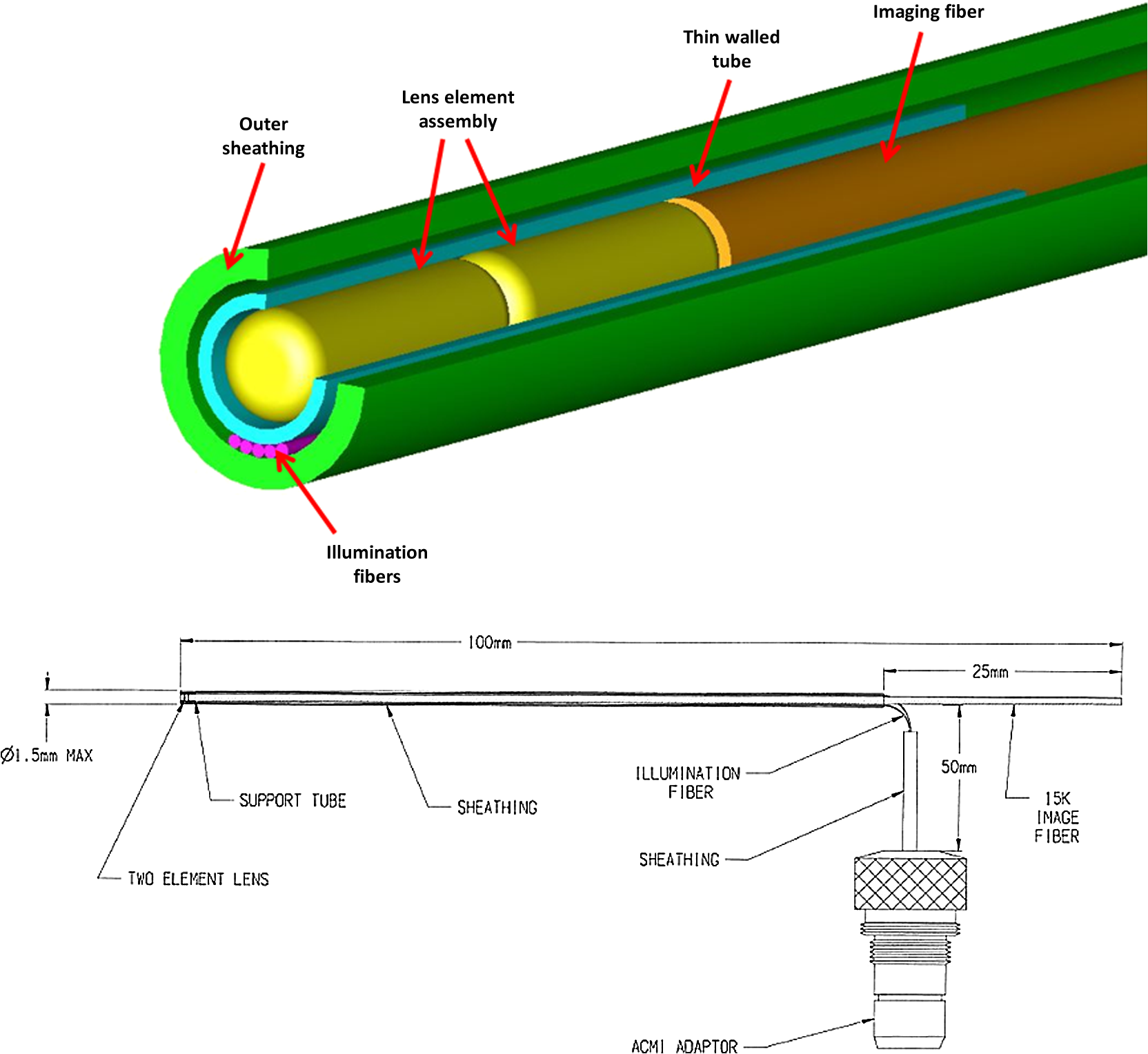
1.IntroductionRoot canal visualization plays an increasingly important role in endodontic surgery, since it enhances precision and results in better outcomes for combating pulp infection.1 The most widely used imaging device is the endodontic operating microscope (OM), and its adoption has helped ease the completion of previously impossible/difficult procedures for clinicians.2 The American Association of Endodontists (AAE) declared in a position statement, that as of 2007, 90% of endodontists have access to and use the endodontic microscope in their practice.3 Many studies highlight the advantages of using the OM. For example, by using the OM, Görduysus et al. improved the ability to negotiate canals in maxilliary molars.4 Another application involved therapy for “dens invaginatus,” a tooth abnormality where the coronal enamel and dentin fold inward toward the pulp cavity. This required the OM for proper management of the complex tooth morphology.5 However, the efficacy of root canal surgery is still being hampered by some limitations in therapy imaging technology. Such challenges include the relative inconvenience in using the OM due to size and cost of equipment. Furthermore, there are ergonomic concerns with the use of current equipment that need a lot of careful positioning,6 resulting in back pain due to incovenient postures. To address the size and usability concerns, endoscopes have also been applied for endodontic purposes.7,8 Shubhashini et al. reported the use of 30- and 70-deg endoscopes for microsurgical procedures.9 Endoscopes have also been shown to have comparatively high sensitivity for in vitro studies involving the correct identification of dentinal cracks10 and visualization of interradicular structures.11 A discussion on the use of endoscopy in endodontics, highlighting its ease of use and visualization during dental procedures, was undertaken by Moshonov and Nahlieli.12 Commercial endodontic endoscopes currently exist in the market. Examples include the Karl Storz oral surgery endoscopes, which have been adapted for oral use. They have the advantage of having small tips (as small as 2.2 mm outer diameter), but have to be directly wired to a viewing device. This complicates use with one hand while performing a dental procedure with the other. Other instruments such as the Henan Milo and Discovery Ultra wireless intraoral camera have the benefit of being wireless and hence are more flexible. Nevertheless, these particular devices have relatively large tips that are unsuitable for root canal surgery. This manuscript reports on the development of a handheld wireless imaging device that delivers clear images of the pulp chamber with sufficient resolution, using commercial and comparatively inexpensive components. Our work is a direct result of an NIH small business innovative research (SBIR) phase 1 grant award to explore the feasibility of our invention for root canal imaging. In addition, we show that using relatively standard off-the-shelf components, our instrument, called the pulpascope, satisfies several constraints for root canal imaging such as adequate pulp cavity illumination, high fidelity image relay, and near real-time wireless image transmission. This latter constraint is particularly important as a wireless device provides more flexibility with single-hand control and helps to satisfy the ergonomic constraints of the OM without sacrificing image quality. 2.DesignThe pulpascope addresses core requirements of sample illumination and relay by the choice and design of its components. These decisions were determined by cost, accessibility, and efficiency considerations. Briefly, the sample surface is illuminated by a fiber bundle, and the scattered light is imaged by the gradient-index (GRIN) element assembly into an imaging fiber bundle. This coherent imaging bundle transmits the image information along its length, and the image is subsequently relayed to a CMOS sensor by a combination of an objective lens and a tube lens. Figure 1 shows the components incorporated in the imaging scheme and the ray path from sample to camera sensor. Fig. 1Block diagram showing optical train. Components highlighted are (a) integrated fiber bundle, (b) light source, (c) Relay module consisting of: [c1] objective lens and [c2] tube lens, and (d) camera module.  2.1.Integrated Illumination and Relay Fiber BundleThe tight coupling of the illumination and imaging fibers yields a compact and efficient design for the pulpascope. The arrangement in Fig. 2 consists of a coherent imaging fiber bundle surrounded by concentric incoherent illumination fibers and terminating with a two-element lens assembly at the distal end. The motivation for the arrangement of the outer fibers is to provide uniform illumination of the target. The inner fiber bundle, which is made coherent for faithful image relay, has elements and an operating minimum bend radius of 60 mm. The total outer tip diameter of 1.5 mm makes this a very viable option for viewing root canals. Each fiber in the bundle has a single core diameter of and a length of 100 mm. The two-element lens assembly focuses at 3 mm with a field-of view of 70 deg. On the other end, the two-fiber bundles are separated, with the illumination fiber connecting to American Cystoscope Makers Inc. (ACMI) adapter that feeds light from a source and the imaging fiber directed toward the relay module. 2.2.Illumination SourceA 15 lumens commercial LED source with surface dimensions of is used as the source of lighting. The size is chosen for compactness and better fitting with the ACMI adapter of the illumination fiber bundle. It has an operating DC voltage of 9 to 15 V at a current of 20 mA and is connected via a small wire to a battery. 2.3.Relay ModuleSeveral practical concerns call for image relay using free space optics from the tip of the imaging bundle to the surface of the CMOS sensor. One is the use of a transparent surface above the sensor for protection, which limits the extent to which the fiber bundle gets close to the sensor. Moreover, it is preferable to avoid touching the surface of the sensor. In similar fashion to a microscope, an infinity-corrected objective lens (Spencer 0.66 NA) and a tube lens (25.6 mm) are used. This combination largely handles the issues of chromatic and spherical aberrations with lenses. Also, the use of the infinity-corrected objective enables more flexibility in distance settings. 2.4.Camera ModuleFor such a portable device, the sensing unit needs to have a wireless power source and image transmission capabilities. A good candidate for this prototype is the Moticam MCX2 Wi-Fi color camera module. Its CMOS sensor has a pixel pitch of , and it is connected to a Wi-Fi transmitter that sends the images to a viewing device with digital zoom capabilities. The camera module is powered by a rechargeable 1300 mAh battery, which experiments show can support of continuous image transmission. 3.Experimental SetupFigure 3 shows the setup of components on a laboratory optical bench. An artificial sample tooth is drilled to simulate a tooth pulp and then placed on an optical platform. The integrated fiber bundle is positioned on an imaging platform, while the relay lenses are housed in a lens tube and mounted on an adjustable height V-Clamp for proper alignment and positioning. The housing tube is screwed onto the camera module via the C-mount. 4.Integration4.1.Computer-Aided Design and Rapid Prototyping of Fiber HolderThe pulpascope fiber holder was modeled in three-dimensions (3-D) using PTC Creo Parametric 3.0 (one view shown in Fig. 4). It has a broad base that can fit into a 25-mm-diameter lens tube via an external thread to optic mount adapter, and terminates via a curved tip of diameter at the other end. A hollow spacing for the fiber runs through the case, with a side entry point for the illumination. The holder was then 3-D printed on a PolyJet Objet Eden 350 machine using Vero Black material. 4.2.Assembled PrototypeFigure 5 shows the prototype of the pulpascope. Lens tubes with retaining rings were used for careful alignment and fine scale adjustments. 5.Results and DiscussionOverall, the pulpascope achieves the goal of ease-of-use and cost effectiveness in preliminary imaging results. The cost for design and assembly of the pulpascope was and greater convenience in its use addresses the ergonomics concerns. 5.1.ResolutionThe resolution of the imaging system, defined as the smallest element imaged, is limited by a single core of imaging fiber bundle. The small tip of the integrated fiber bundle is ideal for imaging narrow regions of the root canal. The two-lens assembly of effective diameter 0.5 mm focuses at 3 mm. Since this lens assembly has an angular FOV of 70 deg, a circle of radius 4.7 mm can be imaged at the focal plane (Fig. 6). This means there is a demagnification of from the sample plane to the surface of the coherent fiber bundle. Each fiber in the bundle has a diameter of and hence, the resulting resolution of the pulpascope is given by . This implies that a circle of diameter fits within the fiber diameter after demagnification for relay through the pulpascope. For better resolution, the GRIN lens arrangement can be made to have a lower demagnification, giving a higher resolution, but at the expense of the FOV. Figure 7 shows images obtained at different distances with ambient laboratory lighting. 5.2.IlluminationLighting plays a major role in the quality of images obtained. Figure 8 shows the images of the drilled tooth at different distances and lighting conditions and/or sources. Fig. 8Images of tooth with light from (a)–(c) 30 W halogen bulb, (d)–(f) laboratory flashlight, and (g)–(h) 15 lumens LED. Note that there is no ambient light. Each scale bar is 1 mm.  A 30-W laboratory halogen bulb fed through the illumination fiber created saturated images with glare, whereas the 15 lumens little dot LED source created inadequate illumination. A laboratory flashlight created better images than the previous two. By using a light source with adjustable brightness, the quality of images can be altered to suit a user. 6.Future Work and ConclusionThis project has shown the development of a handheld wireless dental imaging device with strong potential for accurate visualization of the root canal during surgery. The pulpascope was developed using a 15,000 coherent fiber bundle, with each fiber having a core diameter of . The tooth is illuminated by a light source, and the image is relayed to a sensor, which transmits the image to a viewing device. This combination of the benefits of an endoscope with wireless transmission capabilities gives the pulpascope an advantage over existing systems. We are currently in the next stage of translational development, which focuses on miniaturization, weight reduction, improved battery life, and further ergonomics improvement. Resolution enhancement can be achieved with the adjustment of GRIN lens parameters at the tip. Also, the ability to vary the illumination of a small and powerful light source, using a knob for instance, will afford the user necessary control for adequate imaging. AcknowledgmentsThis work was supported by the National Institutes of Health Grant No. R43DE024345-01. The authors acknowledge financial interest in Moon Ark Inc., which developed the instrument described. ReferencesP. Michaelides,
“Use of the operating microscope in dentistry,”
J. Calif. Dent. Assoc., 24
(6), 45
–50
(1996). Google Scholar
G. B. Carr and C. A. Murgel,
“The use of the operating microscope in endodontics,”
Dent. Clin. North Am., 54
(2), 191
–214
(2010). http://dx.doi.org/10.1016/j.cden.2010.01.002 DCNAAC 0011-8532 Google Scholar
“AAE position statement: use of microscopes and other magnification techniques,”
J. Endod., 38
(8), 1153
–1155
(2012). http://dx.doi.org/10.1016/S0099-2399(12)00624-3 Google Scholar
M. Ömer Görduysus, M. Görduysus and S. Friedman,
“Operating microscope improves negotiation of second mesiobuccal canals in maxillary molars,”
J. Endod., 27
(11), 683
–686
(2001). http://dx.doi.org/10.1097/00004770-200111000-00008 Google Scholar
H. Kato,
“Non-surgical endodontic treatment for dens invaginatus type iii using cone beam computed tomography and dental operating microscope: a case report,”
Bull. Tokyo Dent. Coll., 54
(2), 103
–108
(2013). http://dx.doi.org/10.2209/tdcpublication.54.103 BTDCAV Google Scholar
A. Castellucci,
“Magnification in endodontics: the use of the operating microscope,”
Endod. Pract., 6 29
–37
(2003). Google Scholar
S. A. Held, Y. H. Kao and D. W. Wells,
“Endoscopean endodontic application,”
J. Endod., 22
(6), 327
–329
(1996). http://dx.doi.org/10.1016/S0099-2399(96)80270-6 Google Scholar
J. Marshall et al.,
“An endodontic fiber optic endoscope for viewing instrumented root canals,”
J. Endod., 7
(2), 85
–88
(1981). http://dx.doi.org/10.1016/S0099-2399(81)80248-8 Google Scholar
N. Shubhashini et al.,
“Endoscope assisted endodontic surgery,”
J. Conserv. Dent., 9
(2), 81
–84
(2006). http://dx.doi.org/10.4103/0972-0707.42363 Google Scholar
C. C. Slaton et al.,
“Identification of resected root-end dentinal cracks: a comparative study of visual magnification,”
J. Endod., 29
(8), 519
–522
(2003). http://dx.doi.org/10.1097/00004770-200308000-00007 Google Scholar
W. Engelke et al.,
“In vitro visualization of human endodontic structures using different endoscope systems,”
Int. J. Clin. Exp. Med., 8
(3), 3234
(2015). Google Scholar
J. Moshonov and O. Nahlieli,
“Endoscopy in endodontics,”
Alpha Omegan, 104
(1/2), 26
–34
(2011). Google Scholar
BiographyChukwuemeka Okoro received his bachelor’s degree in electrical engineering from the University of Lagos, Nigeria, and his master’s degree in electrical engineering from the University of Illinois at Urbana Champaign (UIUC). He is a doctoral candidate in the Department of Electrical and Computer Engineering at UIUC. His research interests include nonlinear biomedical imaging and image processing. Albert Vartanian is a practicing general dentist in Los Angeles. He is the founder and president of Moon Ark Inc., a company that is responsible for inventing new instruments that are designed to facilitate and advance dental practices. He and his company conduct collaborative efforts with leading engineers at the University of Illinois at Urbana-Champaign in research and development of technology for dental surgery. Kimani C. Toussaint, Jr. is an associate professor at the Department of Mechanical Science and Engineering, and an affiliate in the Departments of Electrical and Computer Engineering, and Bioengineering at the University of Illinois at Urbana-Champaign. He directs an interdisciplinary lab that focuses on developing optical techniques for quantitatively imaging collagen-based tissues, and investigating the properties of plasmonic nanostructures for control of near-field optical forces. He is a senior member of the SPIE, OSA, and IEEE. |