|
|
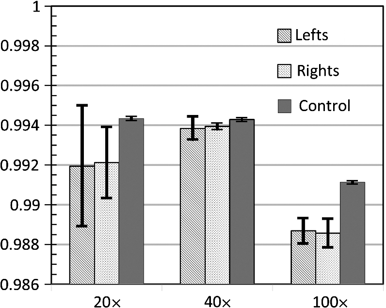
1.IntroductionImage disparity, provided by slightly different view angles, is one of the most important depth cues for depth perception.1 Compared with nonstereomicroscopes, stereomicroscopes can provide more information about the microscale morphology and topology of a desired sample.2 Depth perception of a sample object provides an opportunity for adequate preparation of the sample, as well as an ability to intervene and interpose on the microscopic level.2–4 There are two design types of optical stereomicroscopes: (1) Greenough, which utilizes two separate objective lenses and light channels, and (2) common main objective (CMO) stereomicroscopes, which benefit from a single large objective lens, two light channels, and two eyepiece lenses.5–7 Regardless of image quality considerations, both designs usually have the following three main limitations: (1) limited resolution and magnification, mostly limited to objectives, (2) fixed or not fully adjustable optical channels, and (3) the necessity to use higher quality and higher cost channel components, compared with conventional two-dimensional (2-D) optical microscopes.6,7 While the convergence angle between the left and right views should be under 10 deg to 15 deg for optimal stereovision,5 both of the aforementioned stereomicroscope designs are not satisfactory for high-resolution biological and research microscopy, owing to their objective characteristics.6,7 It is theoretically possible to design two small, tight optical channels that are very close to each other in CMO stereomicroscopes for overcoming this limitation. For example, liquid crystal technology and spatial light modulators were recently used in some microscopy studies for generating stereo images.8 With this technology, part of the incoming light is lost. In addition, the resulting system is still expensive and does not have fully adjustable image disparity for perfect stereovision. Different objectives have different working distances and nosepiece opening diameters; therefore, the diameter and position of the optical channel must be changed in stereo imaging to preserve a perfect view angle.5 These limitations preclude the use of optical stereomicroscopy in applications that require high magnification such as imaging of biological systems. Most of the existing commercial optical stereomicroscopes support only a single camera output, and the term “stereo” primarily refers to two eyepiece lenses. In some cases, stereo imaging is established using two camera outputs;4 however, this results in a significantly higher cost and larger device size. Additional limitations are posed by difficulties associated with the optical setup, data transfer, and color balance characteristics of cameras.1,9 In addition, difficulties with two-dimensional/three-dimensional (2-D/3-D) mode conversion must be accounted for when using these microscopes. Of course, nonoptical methods, such as electron microscopy, are widely used in stereomicroscopy;2,10 however, they are not as easily available as optical microscopes and have their advantages and disadvantages. Further, working with two eyepiece lenses is in many cases irritating and causes a significant physical fatigue of eyes and neck during long-term observations.9,11 Such side effects also occur while working with one eyepiece, regardless of the microscope type. However, using a camera in a microscope has some advantages such as higher magnification, a more comfortable observation, prevention of phototoxic and sample photobleaching, eye safety considerations of light protection, storage, data sharing, and invisible light source application. In a previous study, we introduced a single-channel stereoscopic video imaging modality based on a transparent rotating deflector (TRD) for macrolevel stereo imaging.9,12,13 Therewith, stereo images of left and right pairs were generated by the refraction of light that passed through a TRD.9,13 Here, we introduce a single-channel optical video stereomicroscope (SOVSM), which uses the principle described in our previous study. This stereo imaging method may be compatible with various types of microscopes such as bright-field microscopes, dark-field microscopes, light sheet microscopes, and fluorescence microscopes. This study utilized a bright-field microscope for investigating the feasibility of the SOVSM. The SOVSM used common , , and objectives for visualizing samples of blood cells and a piece of cleaning tissue and was characterized by evaluating: (1) the corresponding rotation angle of the TRD for human stereovision, (2) the required torques for different rotation angles of the TRD as a function of the rotation speed, and (3) the stability of the image quality under the TRD rotation, for different magnifications. 2.Materials and Methods2.1.System SetupA National Instruments (NI) data acquisition system was used over digital I/O ports for managing and synchronizing the illumination, motor, and camera. Utilizing LabVIEW, the NI data acquisition (DAQ) system (NI PCI-6115, 64 MS Memory, 12 Bit, ) was programmed and controlled in real time. The rotation angle and the rotation speed of the TRD, the camera exposure time, the illumination mode, and the timing of the delay were defined by the user through the LabVIEW interface during real-time imaging and display. Figure 1 shows the time and motion profiles of one cycle of operation controlled by the NI DAQ. Fig. 1Timing and motion profiles of one cycle of operation of stereo imaging. Top: the status of illumination and the camera exposure; Middle: the TRD position; and bottom: the DAQ signal generation. Depending on the desired rotation angle and motor type, the controller unit (the DAQ system) sent a number of signals that were translated into mechanical rotation (counterclockwise for rotation from to and vice versa clockwise) in the motor; afterward, a rest time was provided for settling the TRD, for eliminating possible vibrations. Later, the controller unit triggered the camera and the light source, which was followed by the predetermined exposure time. Immediately after capturing the image, the controller unit signaled for backward rotation at exactly the same time as that of the forward rotation.  An inverted optical microscope was setup using a cold white LED and , , and standard objectives (Olympus; Plan N, Japan). The TRD was made from an optical glass of SF10 with the refractive index of 1.7; it had a entrance window and was 18-mm long. It was mounted on a two-phase hybrid step motor (Applied Motion; HT17-278) for continuous rotation in an arc and placed across the light pathway in a lens tube. A complementary metal-oxide semiconductor (CMOS) camera (Basler, acA1600-60gc) with an achromatic doublet lens with the focal length of 300 mm was used for obtaining stereoscopic video images. Figures 2(a) and 2(b) show the optical setup of the SOVSM. 2.2.Stereovision Convergence AngleThe rotation angle of the TRD was calculated by considering the convergence angle of the imaging axes at the specimen, , the TRD size, and the objective characteristics (see Fig. 3). In the calculation, the cover glass of the specimen was not considered. Furthermore, it was assumed that the specimen was located in the front focal plane of the objective in air (); therefore, the TRD was located within the infinity space. Thus, where is the distance between the imaging axes at the objective front lens surface, WD is the working distance (the front focal length of the objective), is the convergence angle of the imaging axes at the specimen, is the effective diameter of the objective front lens, and is the objective view angle, represented by the numerical aperture (NA):Fig. 3Relationship between the convergence angle of the imaging axes and the TRD rotation angle. The TRD generates two parallel imaging axes, which converge at the specimen by the objective. The convergence angle depends on the characteristics of the objective and the TRD and on the TRD rotation angle. 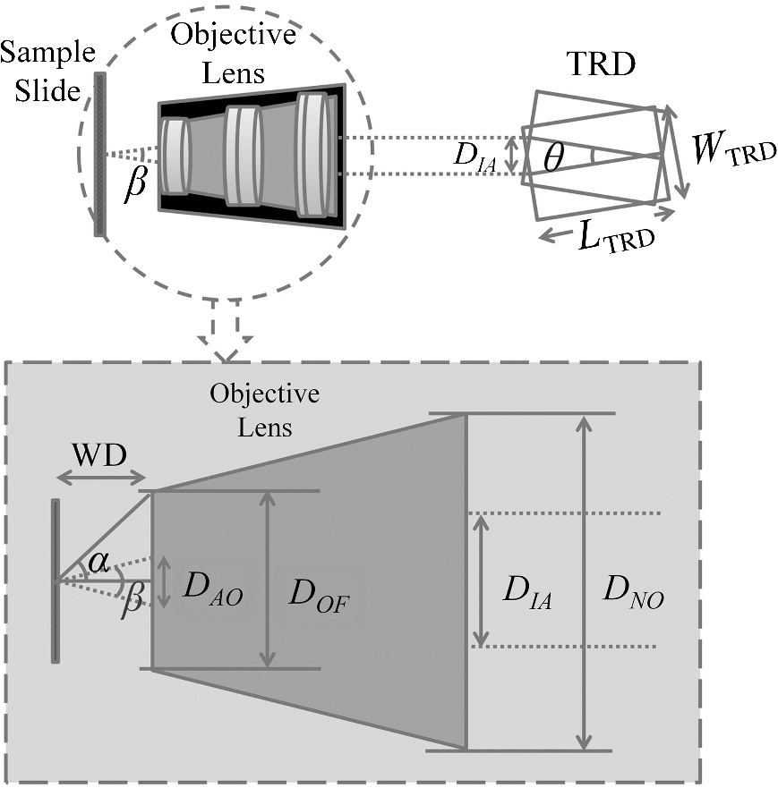 Therefore, when the effective area of TRD is smaller than the incoming light beam’s diameter, and the TRD is fully in the light pathway during rotation, the displacement of the imaging axes due to the TRD, , and the TRD rotation angle, , is defined by and where is the internal diameter of the objective at the nosepiece opening, is the TRD length, and is the refractive index of the TRD. Please note that the TRD can be designed for various types of objective lens and rotation angles; therefore, depending on the diameter of an incoming light beam arriving from a specific objective, the extra part of the TRD face should be blocked and is not expected to affect the calculation. Otherwise, when the effective area of the TRD is larger than the diameter of the incoming light beam or when it is partially out of the light beam’s pathway during rotation, the and the rotation angle of the TRD can be expressed as follows: where is the TRD width (Fig. 3).2.3.Required Torque and Imaging Speed CalculationTo estimate the holding torque of the motor, the possible rotation time (), and the speed of the designed TRD, we calculated the minimal required torque and the rotation time from one position of TRD () to another position () (see Fig. 1) for each image acquisition, as a function of the rotation speed. Torque is a tendency of a force to rotate an object about an axis and is defined by where is the moment of inertia of the TRD and is the angular acceleration. To calculate the minimal torque to generate the desired motion profile, the TRD angular acceleration and deceleration were assumed to be constant during the rotation. Therefore, where is the TRD rotation angle and is the rotation time, which is a function of the rotation speed.2.4.Evaluation of Image Quality StabilityStructural similarity (SSIM) indexing14 was employed for investigating the possible vibration effects of the TRD rotation on the image quality stability. Although SSIM indexing has already been used in our previous study,9 here, microscopic images of a stable sample under constant illumination, focus, magnification, exposure time, and imaging rate were used for investigating whether or not the TRD rotation affects the image quality. For this, two separate test groups consisting of 100 consecutive left and right view images were proposed. Consecutive images in each test group were compared in pairs based on the SSIM index. In a control group, the same comparison was performed for consecutive images while the motor was turned off. In addition, four ranges of SSIM indices were considered for classifying the visual stability of image quality: values below 0.9 corresponded to low stability and high-image distortion, values in 0.9 to 0.95 range corresponded to acceptable image quality stability, values in 0.95 to 0.99 range corresponded to good stability of image quality with insignificant distortion, and values above 0.99 corresponded to an excellent stability. 3.Results3.1.Stereovision Convergence AngleTable 1 shows the required rotation angle of the TRD, (in deg), for different values of (in deg) for , , and objectives. Table 1Required rotation angle, θ (in deg), for different values of β (in deg) for 20×, 40×, and 100× objectives.
Clearly, a more accurate calculation requires more detailed knowledge of the objective design and components, which can be provided by the manufacturers. Note that the TRD rotation angle should practically be slightly larger than the one calculated theoretically to compensate for some neglected issues, such as the light divergence effect in the lens tube. 3.2.Required Torque and Imaging Speed CalculationThe required torque was calculated as a function of the rotation speed for different rotation angles [Fig. 4(a)]. Here, the direction of gravity and air resistance effects were not considered, owing to their very small influence. In the setup, the moment of inertia of the TRD and its mount were calculated as . Fig. 4(a) The required torque and (b) the rotation time per image, as a function of the TRD rotation speed, for different rotation angles. 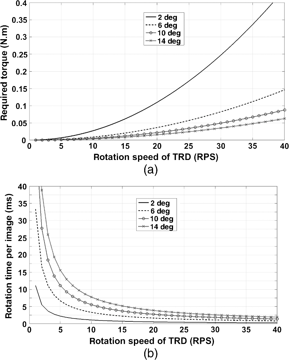 Regardless of the capability of the camera and the exposure time, there is a maximal imaging rate based on the motion profile, owing to the rotation time and the duty cycle available for imaging. Figure 4(b) shows the rotation time per each image, as a function of the rotation speed, for different rotation angles. 3.3.Evaluation of Image Quality StabilityThe images were compared with samples of blood cells and a piece of cleaning tissue, using , , and objectives at an imaging rate of 16 fps, with a 1-ms-long exposure time. The TRD rotation angle, , was 10.8 deg for the , 5.4 deg for the , and 5.4 deg for the objective. Figures 5(a), 5(b), and 5(c) show side-by-side stereo image pairs of a blood cell sample using the objective and a piece of optical cleaning tissue using and objectives, respectively. Figures 5(d), 5(e), and 5(f) show the stereo type of red-cyan composite view of Figs. 5(a), 5(b), and 5(c), respectively. Figures 5(g), 5(h), and 5(i) show the image differences between left and right views in Figs. 5(a), 5(b), and 5(c), respectively. The differences between left and right views present the additional depth information provided by the SOVSM. Figure 6 shows the stability results of image quality assessment based on the SSIM index. Although the results demonstrate a little change in terms of the SSIM index stability for sequential image pairs in left and right views under the TRD rotation when compared with the control group, most of the test groups still demonstrated excellent image quality stability (). Fig. 5The blood cell sample using the objective [(a), (d), and (g)] and a piece of optical cleaning tissue using [(b), (e), and (h)] and [(c), (f), and (i)] objectives. (a)–(c) Side-by-side stereo images; (d)–(f) the red-cyan composite view of stereo images; and (g)–(i) differences between left and right views. The red scale bar is .  4.DiscussionStereomicroscopes are essential for magnifying small objects in 3-D, which provides depth information compared with monocular microscopes. In this study, an effective method has been proposed for enhancing stereo imaging and stereovision for optical microscopy applications. Compared with binocular stereomicroscopes, SOVSMs may be much safer and easier to operate from the user’s point of view, while also enabling multiuser observation, storage, and sharing of stereo images. In addition, SOVSM does not require additional camera and high-quality optical components that are required by CMO stereomicroscopes. Furthermore, the proposed microscopy method significantly improves stereovision and decreases side effects associated with long-term use, owing to its adjustable image disparity and view angle.9 Although most of the existing CMO stereomicroscopes use two fixed light pathways for each eyepiece or camera channel,4,5 the SOVSM adjusts the light pathways depending on the user’s preferences. Different objective lenses with different magnifications, working distances, and numerical apertures result in different convergence angles; therefore, fully adjustable light pathways are essential for achieving compatible stable image disparity and the view angle of human vision. Ignoring such points in the optical setup of stereomicroscopy causes stereovision side effects and incompatibility during long-term observations. The management of the effective area of the objective lens for each view is one of the primary advantages of the SOVSM adjustability over the other types of single objective lens stereomicroscopes. While CMO stereoscopes use an effective area of at most less than half of the objective lens area for each optical channel,5–7 the effective area of the SOVSM varies depending on the TRD size and rotation angle. In other words, the physical size and location of each optical channel are independent of the other channels [see Fig. 2(b)]. However, the SOVSM still has some off-axis aberrations because incident light passes through the off-center region of the objective lens, but this is less limiting than the same limitation for CMO stereomicroscopes.5–7 Because all conventional high-NA objectives used in this experiment were designed to be used in centered optical axis, it is not informative and fair to compare the resolution and aberrations of left and right images with central images. Observing a stereo image on a screen, rather than using the eyepiece lens of a binocular microscope, minimizes the fatigue of eyes and neck. Moreover, using the eyepiece lens is not practical, is impossible, or is hazardous in some applications or devices such as invisible photon detection, laser tweezers, and high-resolution fluorescence 3-D microscopy; in these cases, the SOVSM may be advantageous because it provides real-time stereo images on a screen. Notwithstanding the fact that the test groups of the objective did not fall in the excellent stability class of image quality (Fig. 6), they were still in the upper range of the good image stability class (). Comparison of the control groups for all objectives illustrates that the images of the objective are more sensitive to any instability; so that even when the motor was off, intangible instability occurred in the sample stage, sample slide, or elsewhere in the equipment. Considering the large number of frames visualized in a short time, the research-level system setup, and the high SSIM index score of the test results, no limitations on the image quality stability are expected if a more stable mechanical construction and sufficient torque can be supplied. The SSIM indexing was performed to measure the image quality stability in terms of the visual aspects14 of sequential images. However, the image quality itself needs to be investigated in further comparative studies in different applications, while aberration correction methods and image processing solutions are also considered. As mentioned previously, each imaging cycle has a certain dead time that arises owing to the TRD rotation time, which sometimes limits the imaging speed, especially for high-speed imaging. To maintain the efficient use of light exposure to the sample, and to prevent phototoxicity and photobleaching of the sample, illumination was also synchronized with the camera exposure time. While using smaller rotation angles or faster motors with a larger generated torque would augment the imaging speed, it is possible to simply remove the motor from the light beam’s pathway, or turn the motor off, and utilize the benefits of the 2-D imaging mode for faster imaging, if needed. In addition, depending on the application, field of view, and optical resolution of the microscope, one may use a different size of TRD with a lower moment of inertia for enhancing the imaging speed. However, based on our experience, in the majority of cases involving bright-field microscopy, a high-frame rate is not a major concern, and a frame rate is typically restricted by the camera’s capability and is determined by the exposure time. Considering the desired values for the rotation angle, rotation speed, delay time, and exposure time, it is possible to define an exact value for the frame rate in advance. For example, by providing a sufficient torque [see Figs. 4(a) and 4(b)], a rotation angle of 10 deg at the rotation speed of 30 rps would take at most 2 ms. With a 5-ms-long delay followed by a 20-ms-long exposure time, each imaging cycle would be 27-ms long, implying the final imaging speed of . Like other imaging systems, the SOVSM inevitably deals with the inherent limitations of microscopy. The working distance and field of view should be balanced in an imaging system requiring high magnification. High numerical aperture objectives are designed for a very precise and relatively short working distance and depth of field. Although the TRD-based method can be utilized with similar objectives and optical systems of CMOs, this study focused on the development of high-magnification and high-resolution stereomicroscopy, resulting in a shorter working distance and lower depth of field. Depth perception (the quality of a stereo effect) is defined in terms of the convergence angle, , which is limited by NA and . Therefore, NA should be above 0.25 for obtaining proper stereovision; otherwise, the Greenough design could be a better choice than the SOVSM and CMOs. In conclusion, this study demonstrated that the SOVSM could provide a noticeable improvement from two points of view: (1) developing and introducing an approach for high-magnification stereomicroscopy, and (2) opening a window for using the advantages of stereovision in diverse high-resolution optical microscopy fields for the first time. Considering these primary advantages of the SOVSM, we believe that this technology can be utilized in a wide array of practical and basic research applications of microscopy. The contemporary optical setup of the SOVSM on conventional microscopes may make this technology much easier to use and more attractive for future research and commercialization. AcknowledgmentsThis research was supported by the Ministry of Trade, Industry & Energy (MOTIE) and the Korea Institute for Advancement of Technology (KIAT). ReferencesB. Mendiburu, 3D Movie Making: Stereoscopic Digital Cinema from Script to Screen, Focal Express, Burlington, Massachusetts
(2009). Google Scholar
S. Roy et al.,
“Automatic 3D reconstruction of quasi-planar stereo scanning electron microscopy (SEM) images,”
Conf. Proc. IEEE Eng. Med. Biol. Soc., 2012 4361
–4364
(2012). http://dx.doi.org/10.1109/EMBC.2012.6346932 Google Scholar
M. P. Lee et al.,
“A multi-modal stereo microscope based on a spatial light modulator,”
Opt. Express, 21 16541
–16551
(2013). http://dx.doi.org/10.1364/OE.21.016541 OPEXFF 1094-4087 Google Scholar
Z. Hu et al.,
“Fluorescent stereo microscopy for 3D surface profilometry and deformation mapping,”
Opt. Express, 21 11808
–11818
(2013). http://dx.doi.org/10.1364/OE.21.011808 OPEXFF 1094-4087 Google Scholar
P. E. Nothnagle, W. Chambers and M. W. Davidson,
“Introduction to stereomicroscopy,”
(2015) http://www.microscopyu.com/print/articles/stereomicroscopy/stereointro-print.html December ). 2015). Google Scholar
K.-P. Zimmer,
“Optical designs for stereomicroscopes,”
Proc. SPIE, 3482 690
–697
(1998). http://dx.doi.org/10.1117/12.321966 Google Scholar
H. Schnitzler and K.-P. Zimmer,
“Advances in stereomicroscopy,”
Proc. SPIE, 7100 71000P
(2008). http://dx.doi.org/10.1117/12.797409 Google Scholar
M. Hasler, T. Haist and W. Osten,
“Stereo vision in spatial-light-modulator-based microscopy,”
Opt. Lett., 37 2238
–2240
(2012). http://dx.doi.org/10.1364/OL.37.002238 OPLEDP 0146-9592 Google Scholar
E. Radfar et al.,
“Single-channel stereoscopic video imaging modality based on transparent rotating deflector,”
Opt. Express, 23 27661
–27671
(2015). http://dx.doi.org/10.1364/OE.23.027661 OPEXFF 1094-4087 Google Scholar
T. Zhu et al.,
“Quantitative stereovision in a scanning electron microscope,”
Exp. Mech., 51 97
–109
(2010). http://dx.doi.org/10.1007/s11340-010-9378-7 EXMCAZ 0014-4851 Google Scholar
F. L. Kooi and A. Toet,
“Visual comfort of binocular and 3D displays,”
Displays, 25 99
–108
(2004). http://dx.doi.org/10.1016/j.displa.2004.07.004 DISPDP 0141-9382 Google Scholar
E. Radfar et al.,
“Single-channel stereoscopic video imaging modality based on a transparent rotating deflector,”
Proc. SPIE, 9330 93301N
(2015). http://dx.doi.org/10.1117/12.2079267 Google Scholar
B. Jung, W. H. Jang and Y. Bae,
“Three-dimensional stereoscopic imaging modality based on a single optical channel and detector,”
J. Biomed. Opt., 18 116006
(2013). http://dx.doi.org/10.1117/1.JBO.18.11.116006 JBOPFO 1083-3668 Google Scholar
Z. Wang et al.,
“Image quality assessment: from error visibility to structural similarity,”
IEEE Trans. Image Process., 13 600
–612
(2004). http://dx.doi.org/10.1109/TIP.2003.819861 IIPRE4 1057-7149 Google Scholar
|
||||||||||||||||||||||||