|
|
1.IntroductionPhotoacoustic tomography (PAT) is a hybrid imaging modality, gaining importance rapidly in the field of biomedical imaging. It utilizes the high contrast of optical absorption and high resolution of ultrasound imaging.1–3 The potential clinical applications for photoacoustic (PA) imaging include sentinel lymph node (SLN) imaging, breast cancer imaging, brain imaging, temperature sensing, and so on.4–9 In comparison to other optical imaging modalities, such as optical coherence tomography or optical microscopy, PAT has various advantages, such as deeper penetration depth, good spatial resolution, and high soft tissue contrast. In PAT, a pulsed laser light is used to irradiate the tissue sample. The light is absorbed by the chromophores present in the tissue. Due to thermoelastic expansion, the absorbed light produces a local temperature rise leading to the generation of the PA waves. The PA signals are detected by an ultrasonic transducer placed on the surface of the tissue and are used to image the light absorption map inside the tissue. Other than intrinsic contrast (blood, melanin, or even water), several exogenous contrast agents (organic dyes, metal nanoparticles, and so on) were developed to enhance the imaging contrast as well as to do targeted molecular imaging.10–14 In terms of PA signal detection, single element ultrasound transducer-based PAT scanners require mechanical scanning and hence are slow.15 Such, PAT systems will be less preferred in a clinical setup. Therefore, clinical ultrasound array transducers are better suited for clinical applications. Clinical ultrasound imaging systems consist of different types of array transducers (linear, convex, and phased array) and allow the user to choose based on the area/region of imaging. Therefore, integrating PA imaging with the clinical ultrasound system is a better design for clinical translation of PA imaging. Additionally, such a system also provides dual-modality ultrasound as well as PA imaging capability, which will be very useful for clinicians. A multimodal PA ultrasound fluorescence imaging system combining PA, ultrasound, and fluorescence imaging was reported earlier.16 However, such a system may find limitations in acceptance to the clinical community, since it is not integrated with the clinical ultrasound imaging platform. To use a clinical ultrasound imaging platform for PA imaging, one needs to find ways to integrate the light delivery with the ultrasound probe. One can achieve this by modifying the ultrasound transducer itself internally to incorporate the laser light delivery. A pulsed laser diode was integrated inside the linear array transducer to develop an integrated PA ultrasound imaging system.17 The energy of the light source is still quite low for deep tissue imaging (only small diode laser sources can be housed inside an ultrasound probe). Moreover, this involves modification of the ultrasound transducer internally during the probe manufacturing process, leading to a custom-made probe. Hence, the cost associated with it is high. The other, more practical approach is to externally integrate the laser light delivery with the ultrasound probe. This method was used for the guided needle biopsy of the SLN for both preclinical and clinical imaging8,18,19 With this system, it was shown that PA imaging can be done up to a depth of 5.2 cm.20 A clinical ultrasound machine was used for combined PA-Ultrasound imaging at different depths for different types of transducers (liner array, convex array, phased array, and endocavity). Light was coupled externally to the transducer from a portable optical parametric oscillator (OPO) laser with a customized adapter. In vivo PA imaging was done in small animals and a human forearm using a contrast agent.21 The design of this probe holder, which combines the light delivery and the ultrasound probe, is critical for optimizing the light delivery to the target area. There are several factors affecting the light reaching the target object inside the tissue, such as the angle of light delivery, the distance between the ultrasound transducer and the fiber, the distance between the fiber tip and the tissue surface, optical properties of the tissue and the target object, and so on. Using a clinical PA imaging setup, the irradiation distance was optimized for three-dimensional (3-D) scanning of the human forearm.22 Light was coupled externally with a bifurcated fiber bundle at varying angles (20 deg to 80 deg) for PA imaging on tissue mimicking samples. The fiber was placed on one side of the transducer using a clip. The best angles were found to be 40 deg to 50 deg for an imaging depth of 1 to 2 cm.23 The angle of illumination depends on the distances at which the fiber and the ultrasound probe are placed.24 In this work, we optimize the angle of light delivery from both sides of the ultrasound probe using Monte Carlo simulation for light propagation in tissues with embedded sphere (MCES). Experiments were carried out for different imaging depths using a clinical PA imaging setup. In the simulations, apart from the light launching angles, the fiber-to-tissue distance (FTD) and the fiber-to-ultrasound probe distance were also considered. No work has been reported till now on the optimization of the probe holder design using Monte Carlo simulation as a precursor for light delivery from both sides of the ultrasound probe. The probe holder design may also vary depending on the area/organ being imaged. In this work, we focus on SLN imaging. PA imaging for noninvasive SLN identification is a promising tool for breast cancer staging.8,18 SLN biopsy (SLNB) is commonly used for the staging of breast cancer. To visualize the lymph nodes, radioactive colloids together with methylene blue (MB) dye are commonly used. Noninvasive SLN imaging along with percutaneous fine needle aspiration biopsy will reduce the morbidity associated with SLNB. In this work, we used MCES to study the light delivery angle for a range of imaging depths of SLN.25–27 The Monte Carlo code by Wang et al.28 was modified for fiber source illumination and to handle refractive index mismatch of embedded sphere (SLN is modeled as a sphere in this work) and tissue. Previously, Monte Carlo simulations were reported for light optimization for breast imaging,29 however, inclusion of different types of embedded objects (sphere in this case) was not considered. Initially (study 1), the effect of fiber-to-probe distance (FPD) was computed for different angles of illumination (0 deg to 89 deg) for a fixed SLN depth. Then (study 2), we considered the light hitting the transducer (the photons were terminated to keep it simple), which mimics the experimental setup better. Next (study 3), we focused on the effect of FTD for various light launch angles. Lastly (study 4), for a fixed FPD and FTD, the SLN depth inside the tissue was varied and simulations were done for various light launching angles. Reflection of diffuse reflected light back into the tissue by fiber bundle face and probe surface (in contact with tissue) was also considered in studies 2 to 4. Four different probe holders were designed, which were printed using a 3-D printer. Later, experiments were carried out mimicking the simulation setup (study 4). 2.Methods2.1.Monte Carlo Simulation for Designing the ProbeMonte Carlo simulation for light propagation in multilayered tissue (MCML) written in American National Standards Institute (ANSI) C was modified to embed the SLN inside the tissue layer.28,30 The modifications in the code are explained in more detail in the Appendix. Figure 1(a) illustrates the cross sectional view of the simulation geometry at the plane, across axis. Table 1 lists the optical properties used for the simulations.31–34 The ultrasound probe ( along axis) extends into the first layer (water) to contact the tissue. Modifications were also made to simulate the light delivery using the bifurcated fiber bundle, where each end has 800 fiber tips distributed over a plane of . The fibers of diameter (with cladding, core diameter is ) were randomly packed during fabrication. Hence, for simulation, the fibers were randomly placed in the rectangle of with a minimum distance of between the fibers. Two sets of 800 fiber tips were distributed for two fiber bundles. From the generated fiber tips, the minimum distance between the fiber tips was calculated as , the maximum separation distance between the fibers was , and the mean (std) of minimum distance was . The angular distribution of photons exiting the fiber was modeled as a function of its numerical aperture (NA).35 Further explanations are given in the Appendix on how the photons were launched from the fiber bundle. For angular launch from the fiber bundle, the direction cosines of the photons were varied according to the launching angle. Figures 1(b)–1(f) demonstrate the angular launch of the photons for 0 deg to 60 deg launching angles, where FPD is 2 cm and FTD is 1 cm. At higher launching angles, one can see that the photons start hitting the transducer placed in-between the fibers [Fig. 1(f)]. Fig. 1Monte Carlo simulation geometry and fiber-based light illumination design. (a) Schematic diagram of the simulation geometry across the plane. The OF is at a distance of 1 cm on top of the tissue surface where each end has 800 fiber tips. The SLN (sphere with MB here) is embedded inside a semi-infinite tissue medium. Optical properties used in the simulations are given in Table 1. UST, ultrasound transducer; FPD, fiber-to-probe distance; and FTD, fiber-to-tissue distance. (b)–(f) show the laser beam launched on tissue at angles 0 deg, 15 deg, 30 deg, 45 deg, and 60 deg. The distance between the fiber bundles is 4 cm. The views are at azimuthal angle 60 deg and elevation angle 30 deg. 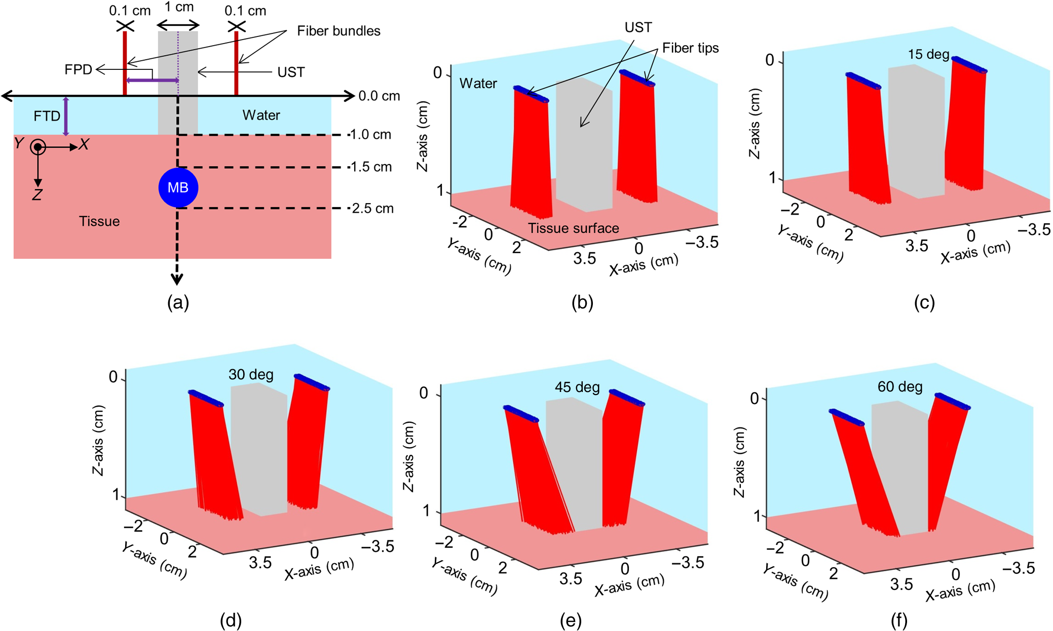 Table 1Optical properties of various elements used in the MCES at 675-nm wavelength.
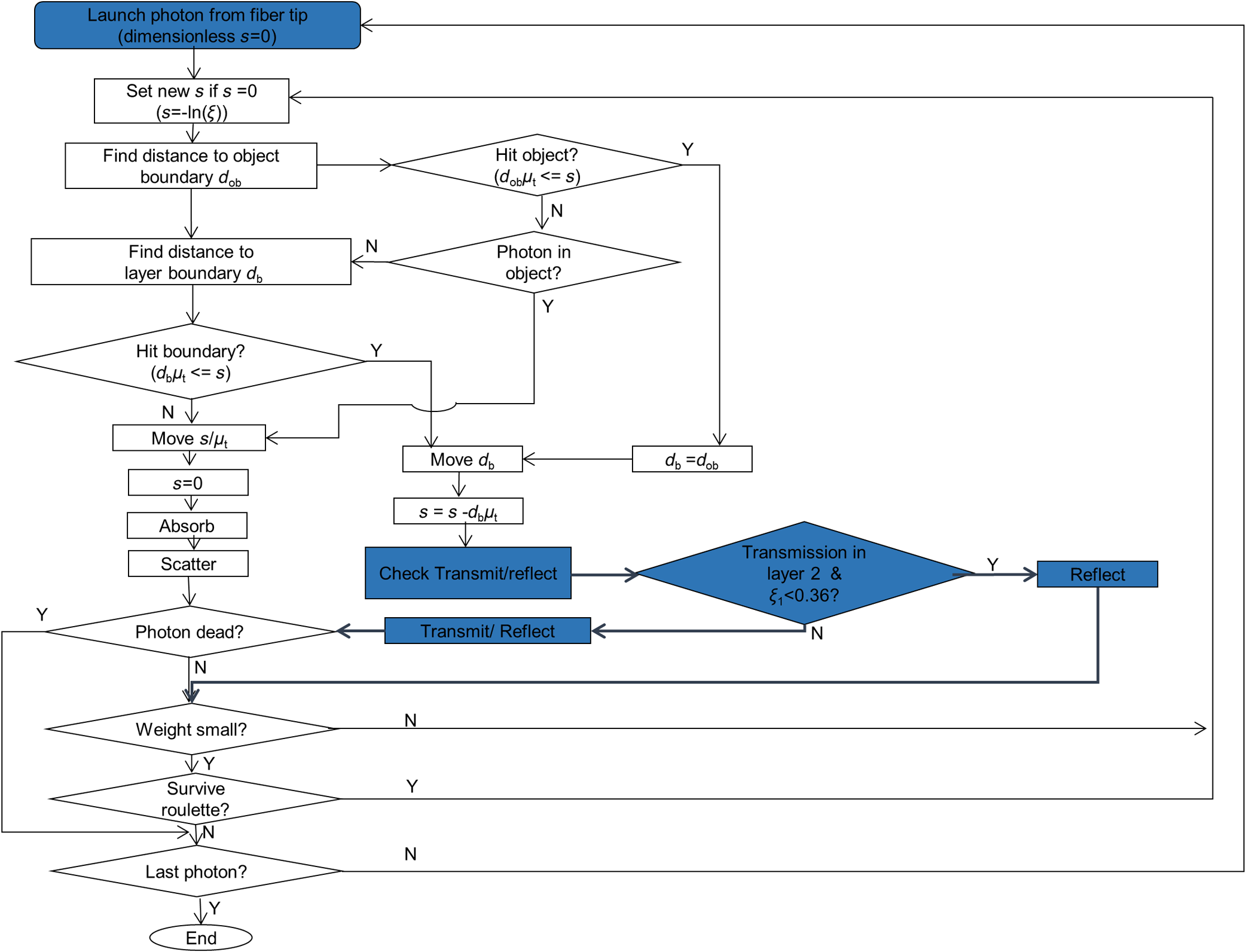
Fiber tips were at plane and the FPD was varied from 1 to 3 cm for an SLN (sphere) placed at a depth (thickness of tissue above sphere) of 1.5 cm. In studies 1 and 2, the angle of illumination was varied from 0 deg to 89 deg in steps of 15 deg, and FTD was a constant of 1 cm. Study 1 was designed to understand the variation of the absorbance in sphere with respect to angle of illumination and change in FPD, when none of the photons was blocked. On the contrary, in our experimental setup, the ultrasound probe was placed in-between the bifurcated fiber bundles. Hence, in simulation, the photons that hit the probe were terminated as seen in study 2. Since the light delivery on tissue is also a function of the FTD, in study 3, FPD was fixed at 2 cm and sphere depth was maintained at 1.5 cm whereas angle of illumination was varied as 0 deg, 5 deg, 10 deg, 15 deg, 20 deg, 30 deg, 45 deg, and 60 deg and FTD was 1, 2, 3, and 4 cm. All the simulations were done with a semi-infinite simulation setup; but in the experimental setup, the size of the tissue medium was finite. In study 4, we considered finite tissue boundaries. For simplicity, the photons that crossed the boundary were terminated. In study 4, the angle of illumination was 0 deg, 5 deg, 10 deg, and 15 deg. Optical properties of the medium, such as absorption coefficient (), scattering coefficient (), scattering anisotropy (), and refractive index (), determine the propagation of the photon.31,30 Here, equal numbers of photons were launched from each fiber tip. Total absorbance in the sphere and distribution of absorbance in 3-D grids were recorded. Total absorbance in the sphere is independent of the element size chosen in the simulation. For the distribution of absorbance, an element size (grid size) of was used. The PA signal generated from the SLN is directly proportional to the absorbance in the sphere. Thus, the absorbance inside the sphere was a good indicator of the strength of the generated PA signal. MATLAB® (MathWorks, Massachusetts) was used for generation of the absorption maps. Studies 1 to 3 were run for 6.4 million photons (4000 photons per fiber tip). Study 4 was run for 16 million photons (10,000 photons from each fiber tip). Convergence analysis was done and the standard deviation of the absorption in the sphere was less than 0.25% when 6.4 million photons were used and less than 0.15% when 16 million photons were used. Each simulation took (for 16 million photons) to run on the desktop. The 3-D design of the fiber holder was such that the distance between the two fiber bundles was not the same for different angles of illumination. For 0-deg holder, the fiber-to-fiber (center-to-center) distance was 3.8 cm; for 5 deg and 10 deg angles, the distance was 3.4 cm; and for 15 deg, the distance was 3.6 cm. These distances were used in simulation of study 4 for consistency between simulation and experimental setup. The thickness of the tissue layer above the sphere was varied from 0.5 to 3.0 cm in steps of 0.5 cm (whereas with respect to plane the center of the sphere varies from 4.0 to 6.5 cm) in study 4. In experimental cases, diffuse reflected photons from tissue are reflected back into the tissue by surfaces, such as stainless steel metal in fiber bundle and the ultrasound transducer. Considering the above reflecting surfaces, 36% of the diffused reflected photons are diverted back into the medium in studies 2 to 4. This reflection of photons in simulation happens at plane. All simulations were done on a desktop computer with an Intel Xeon 3.7 GHz, 64-bit processor, and 16-GB RAM running windows 10 operating system. 2.2.Photoacoustic and Optical Spectrum of Methylene BlueSince MB is a clinically approved contrast agent for SLN imaging, here we have used the same for all our experiments. From the literature, MB has an absorption peak around 668 nm;34 however, the OPO laser used here has a minimum wavelength of 670 nm. To find an optimum wavelength to work, we first recorded the PA spectrum of the MB in the near-infrared (NIR) wavelength range in which the OPO operates. The MB (Sterop, Belgium) was injected into a transparent low-density polyethylene tube with a diameter of 1.15 mm and placed in a water bath. A single element ultrasound transducer (3.5 MHz center frequency) was used to record the PA signal. The signals were first amplified, then bandpass filtered by an ultrasound signal receiver (R/A/F) unit (Olympus-NDT, 5072PR), and then digitized and stored in a desktop with a data acquisition (DAQ) card (Gage, compuscope 4227). The wavelength of the laser was varied from 670 to 870 nm with a 5-nm step size. Each of the obtained PA signals was averaged 10 times. The peak-to-peak PA signal intensity is plotted against the wavelengths. The PA signals were normalized with the laser power. For comparison, the optical spectrum of MB with the UV-visible spectrophotometer (Spectramax M5) was done for the same wavelength range. The concentration of MB used is . 2.3.Design of the Fiber Bundle HolderThe 3-D design of the optical bundle holder was done using a computer-aided design software package Creo Elements/Pro (Parametric Technology Corporation, Massachusetts). The current designs of the holder are inexpensive and easy to fabricate because they are designed as a single piece without any overhanging features and eliminate the need for assembly of parts. The images of the bundle holder design for the various angles 0 deg, 5 deg, 10 deg, and 15 deg are shown in Figs. 2(a)–2(d). These angles were chosen keeping in mind the practical difficulties due to the fiber flexibility and length. The holders were fabricated using 1.75-mm-diameter polylactic acid filament in a desktop 3-D printer (MakerBot Replicator 2, MakerBot Industries, Brooklyn). Replicator 2 printer settings for the various parameters were as follows, high resolution, 15% infill with the extruder temperature at 230°C, and extruder speed of . The fiber holder was designed with two slots to hold two ends of the fiber and a single slot to accommodate the ultrasound transducer. The variations in distance between the fiber-bundles for each of the angles were taken into consideration for simulation. The holder was designed for different angles at which the fiber bundle is fixed. The various angles used for the experiments are 0 deg, 5 deg, 10 deg, and 15 deg. The images of the same are shown in Figs. 2(e)–2(h), respectively. Fig. 2(a)–(d) The drawings used to fabricate the fiber holder with various angles of light delivery, 0 deg, 5 deg, 10 deg, and 15 deg, respectively. (e)–(h) Photographs of the 3-D printed fiber holders. (i) PA imaging system with clinical ultrasound platform. OPO, optical parametric oscillator; OF, optical fiber bundle; FH, fiber holder; USM, clinical ultrasound machine; and L, lens. (j) Zoomed section of the handheld probe and imaging sample, showing the fiber holder with the OFs and transducer. UST, ultrasound transducer and MB, spherical phantom with MB embedded in tissue and placed in a water bath. (k) Photograph of the fiber bundle. (l) Photograph of the input and the output ends of the fiber bundle. The two rectangular parts constituting the output end of the fiber bundle and the input end is of a circular shape. (m) Top view of the fiber holder with the OFs and the transducer attached. (n) Front view of the fiber holder with the OFs and the transducer attached. (o) Chicken breast tissue with the embedded spherical phantom filled with MB. (p) Photograph showing the phantom stacked with 2.5 cm of chicken breast tissue. 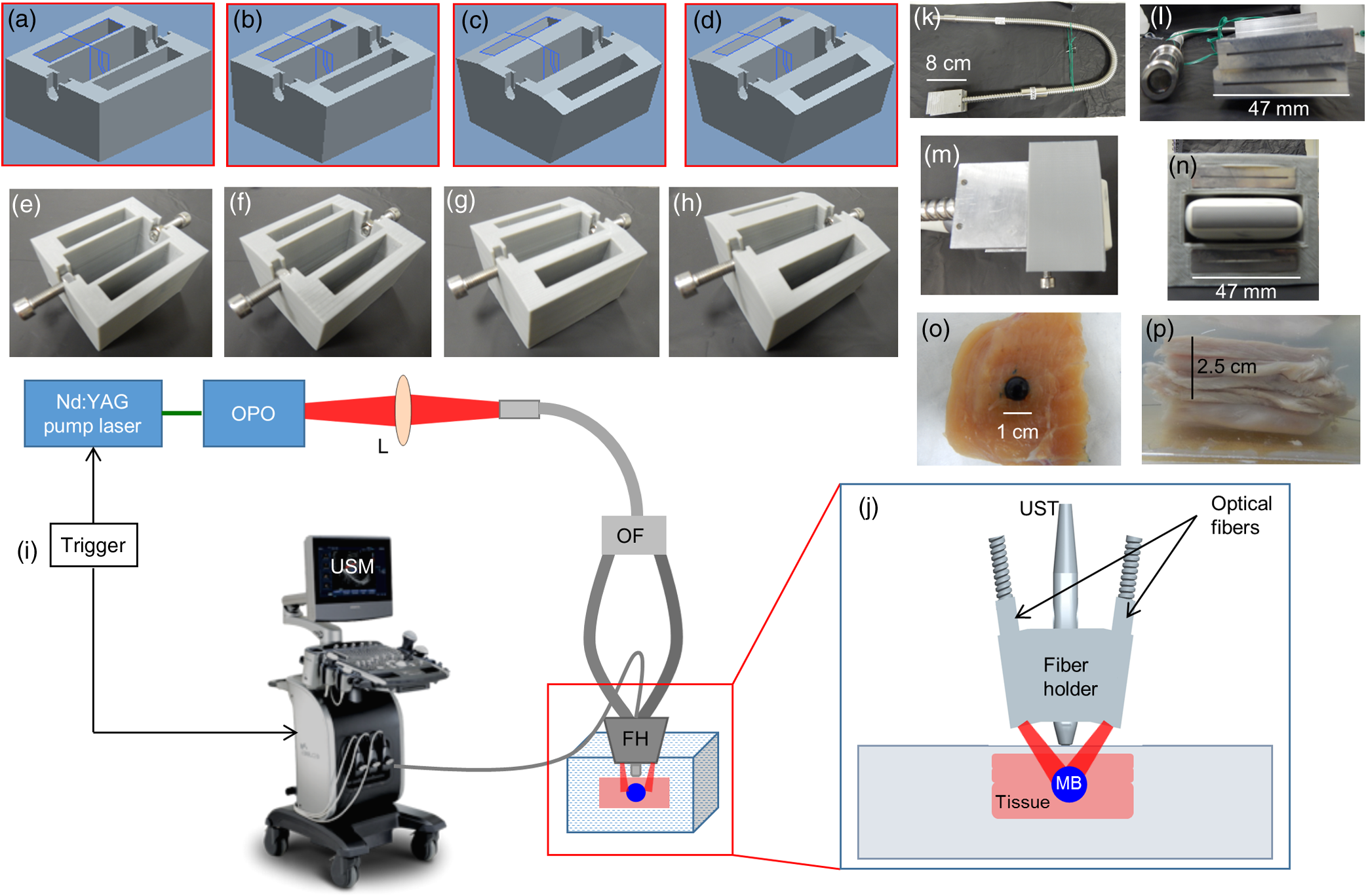 2.4.Photoacoustic Tomography Imaging SystemThe PAT experimental setup is shown in Fig. 2(i) and an enlarged image of the imaging area is shown in Fig. 2(j). The clinical research ultrasound system (E-CUBE 12R, Alpinion, South Korea), capable of dual-modal imaging (both PA imaging and ultrasound imaging), was used in this study. To operate the system in the PA mode, laser excitation needs to be provided in sync with the trigger, which synchronizes the laser excitation and DAQ. The PA signals generated were acquired with a linear array transducer (L3-12 probe, center frequency ). The excitation laser was an OPO (Continuum, Surelite OPO) laser pumped by a frequency doubled nanosecond pulsed Nd:YAG pump laser (Continuum, Surelite Ex). The OPO generates 5-ns duration pulses at 10 Hz repetition rate with wavelengths tunable from 670 to 2500 nm. For the imaging experiments, the laser was tuned to 675 nm. The laser output from the system was delivered to the sample by coupling through a 1-m-long optical fiber (OF) bundle (Ceramoptec GmbH, Germany) containing 1600 fused multimode fibers. The photograph of the fiber bundle is shown in Fig. 2(k). A lens (L) was used to focus the light to the input end of the OF bundle. The fiber bundle was bifurcated toward the end and light output is delivered through two bundles, rectangular in shape and the area from which light is delivered is . Each of this area is comprised of 800 fiber tips. Each fiber has a core diameter of ( with cladding) with an NA of 0.22. The input and the output ends of the fiber are shown in Fig. 2(l). The two output ends of the fiber bundle are fixed in the custom-made probe holder. The energy at the input and the output ends of the fiber was measured and the coupling efficiency of the fiber was . The light energy at the output side of the fiber bundle was per pulse at 675 nm. The radiant exposure on the sample surface was estimated to be (total spot size of illumination from both the fiber bundles is ). Thus, the radiant exposure was within the ANSI safety limit of .36 The ultrasound probe was also fixed inside the fiber holder along with the two fiber ends to make a handheld PA and ultrasound probe. The lateral and horizontal views of the assembled probe are shown in Figs. 2(m) and 2(n). The trigger out from the pump laser synchronizes the DAQ on the E-CUBE system. The PA images are displayed on the E-CUBE screen at a frame rate of 5 frames per second, since two laser shots are required to obtain one PA image. 2.5.Photoacoustic Data Acquisition and Image FormationThe PA signal generated within the sample was acquired using linear array transducer L3-12, which is compatible with the E-CUBE ultrasound system. This system is capable of dual-modality imaging (ultrasound and PA) and has 64 parallel DAQ hardware. In this work, it was operated in the combined mode. This was achieved by operating the system in research mode. In this mode, the parameters, such as the imaging depth, number of frames to be saved, and the type of data to be saved, are specified using a python code. The total imaging depth was set at 4 cm. A total number of 50 frames was saved in the beam-formed datatype. The L3-12 transducer is made of 128 array elements with 8.5-MHz center frequency (95% fractional bandwidth). The active area of the transducer is . Due to the DAQ hardware of the system for each laser pulse fired, data are collected by 64 channels only. Therefore, two laser pulses are needed to obtain data from all 128 channels. Following two laser pulses, the system automatically combines the PA signal obtained by all 128 channels into a single image. The final processed image is displayed on the E-CUBE monitor after it passes through a series of inbuilt filters. 2.6.Phantom ExperimentsImaging with phantoms mimicking SLN was performed. A spherically shaped transparent object was prepared with a commercially available latex material similar to gloves of thickness and filled with 0.5 mL of MB. It was knotted manually to seal in the shape of a sphere of 1 cm diameter to mimic the SLN. The spherical object was completely filled with MB dye at a concentration of . The spherical phantom was embedded in a chicken breast tissue, in thickness. For imaging at various depths, commercially available chicken breast tissue was cut manually in the size and 0.5 cm in thickness. Five such slices were cut and stacked one by one to increase the depth of imaging from 0.5 to 2.5 cm in steps of 0.5 cm. The photograph of the spherical phantom embedded in the tissue is shown in Fig. 2(o). The SLN phantom along with the chicken breast tissue was placed in a water bath in which the handheld ultrasound-laser probe was placed to acquire PA images at different depths and at different angles of the light launch (by using a different probe holder) at FTD 3 cm. The different angles used for light delivery are 0 deg, 5 deg, 10 deg, and 15 deg. The different depths for which phantom imaging were performed are 0.5, 1, 1.5, 2, and 2.5 cm. The photograph of the phantom with multiple layers of tissue is shown in Fig. 2(p). 3.Results and DiscussionSince MB is used clinically for SLN imaging, it has been used as a contrast agent for this study. MB has a peak light absorption at 668 nm. The UV-visible spectrum of MB is shown in Fig. 3(a). Since the OPO laser provides a laser output from 670 nm, it was first checked that the MB can produce a strong PA signal near or above 670 nm. The MB PA spectrum is shown in Fig. 3(b). Note that the maximum peak-to-peak PA signal intensity is at 670 nm. The PA spectrum is in correlation with the absorption spectrum of MB. Although the highest peak-to-peak PA signal was obtained at 670-nm wavelength, it happens to be the starting wavelength of the OPO laser in the NIR range. It was found that the laser output was unstable at the initial excitation wavelength. Hence, in this work, we have used 675-nm wavelength, for both MCES and experimental work. Fig. 3(a) Optical spectrum of MB in the NIR range and (b) PA spectrum of the MB in the NIR wavelength range. The PA signals were normalized by the laser energy at each wavelength.  Monte Carlo simulations were carried out to optimize the light delivery to the SLN as described. The mean (standard deviation) spot size from each fiber bundle is 4.4 (0.58) cm and 0.6 (0.001) cm along - and -axes, respectively. Figure 4(a) shows the absorbance in sphere for variation in FPD (study 1). When the illumination angle is 89 deg (, which implies photons are parallel to the tissue surface), a negligible number of photons enters the simulation medium (yellow star). The maximum absorbance was at 30 deg (blue circle), 45 deg (brown inverted triangle), and 60 deg (blue star) for FPD of 1, 2, and 3 cm, respectively. When none of the photons was blocked by the transducer, with increase in the FPD, a higher angle of illumination was needed for maximum absorbance. Also note that with an increase in FPD the maximum absorption decreases. Hence, to increase the signal (absorbance), one should try to illuminate closer to the object with lower illumination angle. In practice, getting very low FPD is not possible as the ultrasound probe is placed between the fiber-bundles. Fig. 4Simulation results. (a) Study 1: absorbance in sphere for angle of illumination varying from 0 deg, 15 deg, 30 deg, 45 deg, 60 deg, 75 deg, and 89 deg when FPD was increased from 1 to 3 cm (FTD was fixed 1 cm). (b) Study 2: absorbance in sphere for angle of illumination varying from 0 deg, 15 deg, 30 deg, 45 deg, 60 deg, 75 deg, and 89 deg when FPD was increased from 1 to 3 cm with the photons that fall on the transducers being blocked. (c) Study 3: FPD was 2 cm and FTD was varied from 1 cm to 4 cm for angles 0 deg, 5 deg, 10 deg, 15 deg, 20 deg, 30 deg, 45 deg, and 60 deg. (d) Study 4: absorbance in SLN for spheres at depths 0.5 to 3 cm in steps of 0.5 cm when FTD was kept at 3 cm, FPD for 0 deg was 1.9 cm, 1.7 cm for 5 deg and 10 deg, and 1.8 cm for 15 deg. The angles of illumination were 0 deg, 5 deg, 10 deg, and 15 deg. (e)–(h) The absorbance maps of sphere at depth 0.5 cm for illumination angles 0 deg, 5 deg, 10 deg, and 15 deg. 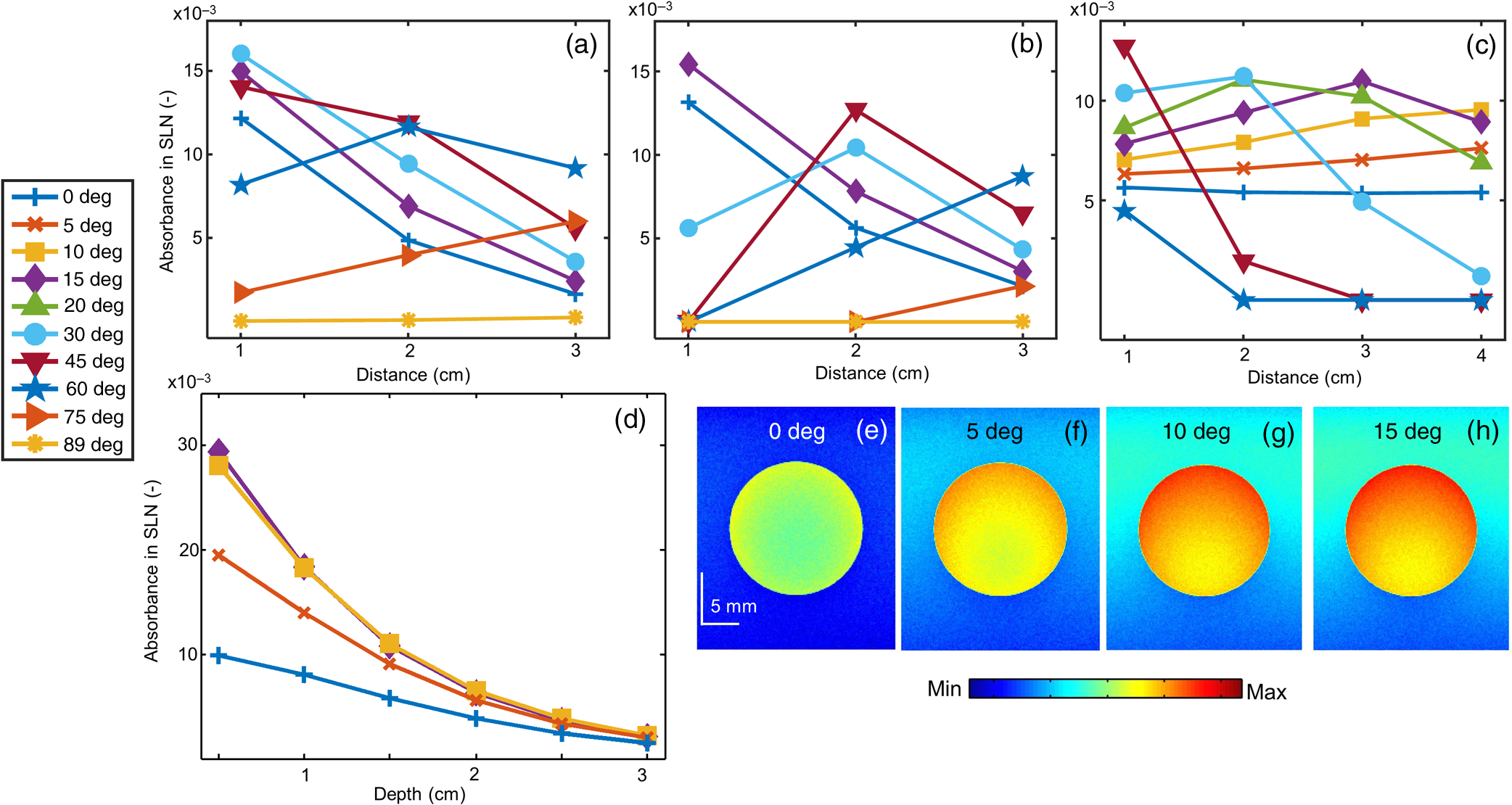 Figure 4(b) shows the results from study 2. It was observed that for lower FPD (1 cm) illumination at 30 deg did not produce maximum absorbance as seen in study 1. This was because of the partial blockage of photons hitting the probe and those photons did not reach the imaging area. At this FPD, illumination at angles higher than 30 deg gave nil absorbance since none of the photons (or very few photons in practice could reach) reached the simulation medium (tissue). For FPD of 2 cm, partial light from 60-deg illumination was blocked and all photons were blocked for illumination of 75 deg (brown right sided triangle) and 89 deg. When FPD was increased to 3 cm, illumination at 0 deg to 60 deg was unaffected, whereas light for 75-deg illumination was partially blocked. Since the absorbance for 75 deg and 89 deg was negligible, these two angles were not considered for further studies. FPD of 1 cm is ideal for getting maximum light reaching the target object (SLN). However, due to the size of the probe, the OF casing, and the fiber holder design, FPD of 1 cm was not realistic and practically feasible. Therefore, FPD of 2 cm was chosen for study 3. Figure 4(c) shows the result of study 3, in which FPD was fixed at 2 cm, sphere was at 1.5 cm under the tissue surface, and the FTD was varied from 1 to 4 cm for illumination angle of 0 deg (blue plus), 5 deg (brown cross), 10 deg (yellow square), 15 deg (purple diamond), 20 deg (green triangle), 30 deg (blue circle), 45 deg (brown inverted triangle), and 60 deg (blue star). With the increase in the FTD, for a higher angle of illumination, the amount of photons blocked increased. FTD was varied from 1 to 4 cm, maintaining an FPD of 2 cm (distance between the probe outer surface and center of fiber bundle is 1.5 cm). Theoretically [], the illumination photons above angles 56 deg, 37 deg, 27 deg, and 21 deg were partially or completely blocked at FTD of 1, 2, 3, and 4 cm, respectively. Hence, for FTD of 1, 2, 3, and 4 cm, an illumination angle of 45 deg, 30 deg, 15 deg, and 10 deg gave maximum absorbance, respectively. The flexibility of the fiber bundle, due to its heavy metal casing, is confined the bending angle to 15 deg. To maximize the light absorbance inside the sphere we chose to use FTD of 3 cm for further study. Study 4 was done to see the effect of different illumination angles at different depths of the SLN. This study was also experimentally validated for SLN (spheres) at different depths. Hence, FPD was chosen within 1.7 to 1.9 cm (which is close to 2 cm) depending on the bundle holder fabricated. Due to the additional limitation of the flexibility of the fiber bundle, the maximum possible illumination angle was 15 deg. At FTD of 3 cm, we observed maximum absorbance at this angle [Fig. 4(c)]. Hence, FTD of 3 cm was chosen for both simulations and experiments in this study. Figure 4(d) shows the absorbance plot (spheres placed at depth 0.5 to 3 cm) for illumination angles 0 deg (blue plus), 5 deg (brown cross), 10 deg (yellow square), and 15 deg (purple diamond). For spheres at depths (0.5 and 1 cm), illumination of 15 deg gave the maximum absorbance and 10 deg gave the maximum absorbance for other depths. Trend in the plots reveals that the angle of launch plays an important role for delivering light from different distances between the fiber probe and fiber tissue. With an increase in the angle of illumination, propagation of photons toward the center of the geometry (closer to the origin) increases the light absorbance in the sphere. The variation across maximum and minimum absorbance in sphere across angles 0 deg to 15 deg in steps of 5 deg was 110%, 86%, 66%, 52%, 42%, and 36% for 0.5, 1, 1.5, 2, 2.5, and 3 cm sphere depth, respectively. Figures 4(e)–4(h) shows the light absorption maps in the SLN at depth 0.5 cm. The 320 million photons were simulated for obtaining the smooth absorption maps. Lastly, experiments were done to validate the simulation results from study 4. Probe holders were designed to hold the fiber bundle at angles 0 deg, 5 deg, 10 deg, and 15 deg. Due to the limited length and limited flexibility of the fiber bundle inclination, more than 15 deg for light delivery was not feasible. Hence, the maximum angle of light delivery was experimentally restricted to 15 deg. Phantom experiments were carried out with all four different probe holders for various SLN depths of 0.5, 1, 1.5, 2, and 2.5 cm. The FTD was kept at 3 cm. Although in simulation 3-cm-deep imaging was done, it was not done experimentally as the PA signals were very weak for this depth (simulation showed that the sphere placed at 3 cm absorbed only one-tenth of the photons in comparison to a sphere placed at 0.5 cm). Figure 5(a) shows the signal-to-noise ratio (SNR) obtained from the beam-formed PA images (after Hilbert transformation) of the SLN phantom using the clinical PA imaging system. The SNR was defined as the amplitude of the PA signal from the SLN divided by the standard deviation of the background noise, , here is the PA signal amplitude from SLN and is the standard deviation of the background noise. To obtain the signal from the SLN, a rectangular region was chosen manually in the area in which the SLN phantom was located. The average of the top 10 pixels in the region was taken as the signal value (). To calculate noise (), a rectangular area was taken near the SLN and the standard deviation was calculated. Using the above two values, SNR was calculated. The size of the region of interest used to calculate the SNR (both signal and noise) was the same for all the images. No masking was used for the selection of the target feature. The SNR is plotted with respect to the depth of the sphere. Multiple plots in the graph represent the different angles of light delivery (or different probe holder). No acoustic attenuation correction was performed for the experimental PA results. Fig. 5Experimental results. (a) Plot showing the SNR of the PA images for various depths of the SLN (0.5, 1, 1.5, 2, and 2.5 cm) and for different light launching angles (0 deg, 5 deg, 10 deg, and 15 deg). FTD was kept at 3 cm. (b) Screenshot captured from the E-CUBE display of the combined ultrasound and PA imaging [the SLN (1 cm diameter sphere filled with MB) was placed at a depth of 0.5 cm under the chicken tissue]. (c)–(f) B-scan PA images at a depth of 0.5 cm for various light delivery angles, all images are shown with the same colorbar.  Trend in the SNR confirms experimentally that probe holder design is important depending on the imaging depths and target locations. At most of the depths, the SNR obtained at 0 deg was the lowest. At shallower imaging depths, the variation in SNR is more than 100%. At an imaging depth of 2.5 cm, the SNR values do not vary significantly, which is as expected. With increase in depth, the SNR drops irrespective of the angle of launch. From Fig. 5(a), it is observed that the maximum SNR was obtained at an angle of 15 deg for 0.5 cm, and for other depths, 10 deg gives the maximum SNR, which closely matches with our simulation results. Figure 5(b) shows the screenshot captured from the E-CUBE display monitor of the combined ultrasound and PA imaging of the SLN at 0.5 cm. The grayscale image represents the ultrasound image and the colored overlap represents the PA. This image is shown to confirm the position of the sphere. For representative purpose, the B-scan PA images of the sphere placed at 0.5 cm depth for different angles of light delivery is also shown. To reduce the effect of energy variation in the laser, the Hilbert transformed PA images shown are averaged from 25 frames (Beam-formed images). Figures 5(c)–5(f) show the PA images at 0.5-cm depth. Comparing the absorbance image obtained from the simulation and the PA image, SNR plot obtained from the experimental results, it is concluded that the simulation data are a close match to the experimental outcome, as the results obtained from both follow a similar trend. It is to be noted that the simulation and the experimental results will not match 100% as there are many factors that cannot be controlled in the experimental scenario including experimental error. Also, we are comparing the absorbance measured in simulations versus the SNR from the PA images, which can lead to minor deviations in the results. However, simulation data can be used as a precursor since the general trend is similar in both cases. Due to practical difficulties, a light delivery angle of more than 15 deg was not done experimentally. For all the depths and for most of the values, the simulation’s absorbance trend coincides with the trend of the PA image SNR obtained from experimental data. Hence, Monte Carlo simulation with embedded objects can be used as a precursor to design the probe for various experimental needs. This highly reduces the trial-and-error method in choosing the angle of light delivery when the object is known to be located at a certain depth or reduces the risk of using just one angle of light delivery, irrespective of how deep the object is. In clinical application, this will be very useful by reducing the amount of exposure to laser light by eliminating the necessity to experiment with different angles of light delivery in order to obtain the best results. Also, if the depth of imaging is known, it greatly reduces the actual imaging time on the patient. There are several factors such as the angle of illumination, the distance between the transducer and the fiber tip, the distance between the fiber and the skin surface, and so on, that can affect the PA signal. Although, we have considered all these factors in simulation studies, experimental validation is provided only for different light illumination angles with respect to depth at a fixed fiber tissue distance owing to practical limitations of the fiber bundle. The kind of imaging setup (imaging area, tissue properties, and so on) one is interested in will also play a key role. For example, here, we have used SLN imaging scenario. For a different application, there will be different types of tissues, and the target object structure could also be different. In this work, we have considered the SLN as a spherical model. We have used this only as a model to demonstrate that simulations can be used as a precursor to optimize clinical imaging. Another factor is the illumination light wavelength. In this particular problem, since MB is used as a contrast agent for the SLN mapping, the excitation wavelength used is 675 nm, since MB has peak absorption close to this wavelength. So to conclude, users may need to do the appropriate simulations with all these factors taken into consideration before designing the probe holder for a particular problem they have in hand. Another challenge is to have a single probe holder in which the angle of illumination can be controlled. At present, we have several separate probe holders and for each angle of illumination we need to change the probe holder. Ideally, one probe holder with flexibility of angle will be better for an in vivo imaging setup. 4.ConclusionMonte Carlo simulations were done to study the effect of the light launching angles on the PA signal amplitude for a handheld PA probe. Different simulation scenarios were considered for the different parameters affecting the imaging. Experimental validation was provided for the different illumination angles at various SLN depths for a given fiber to tissue and FPDs. It is shown from simulations that different illumination angles are needed to obtain maximum absorbance in SLN. Accordingly, several 3-D printed probe holders were designed and PA imaging was done using the clinical ultrasound platform. It was confirmed through experiments that the angle of light delivery plays an important role with respect to the depth of imaging at a given FTD. Studies for other illumination parameters influencing the light absorbance in SLN (such as effect of dimension of SLN) or any other imaging scenario (other body parts/organ) will be part of our future work. AppendicesAppendix:Modification in the Monte Carlo SimulationLaunching of photons in conventional MCML and MCEO is a pencil beam. In the experimental setup, a fiber bundle was used. Hence, the simulations here also needed the fiber bundle. The fiber bundle tips were generated as follows. The fiber core diameter was (with cladding the diameter was ). The fiber bundle fabricated for experiments had 800 tips randomly positioned in a rectangular region of . The core of was approximated to a point source. Hence, for the launch of photons in simulation, 800 points were generated with a minimum distance of between each of them. A random vector of dimension was initialized. The values of the random vector range from 0 to 1. Vector was scaled to 4 and 0.142 to match the probe dimension. A new random vector was generated and scaled. The distance between the previously generated fiber tip and the new vector was computed. If the distance between the vectors was greater than , then the new vector was appended to set final fiber tip positions. The list was grown until 800 points were obtained. Two sets of fiber tips were generated, which formed a look-up table. An equal number of photons was launched from each of the fiber tips. Once launched the position of the photons ( and ) was initialized with the value from the look-up table and was set to 0. Direction cosines of the photon (, , and ) were computed based on the launch angle. With the help of a random number, the further spin angle due to the NA was computed for each photon.35 Spinning of the photon was done in the local co-ordinate system and then the direction cosines were converted back to the global co-ordinate system. Co-ordinate system conversion and spin done here are explained in the original MCML simulation.28 The photon’s conventional steps of scattering and absorption are illustrated in Fig. 6. Exclusively for study 4, when the photons hopped beyond the tissue size ( and ) they were terminated. When the photon was to be transmitted from layer 2 (which is tissue), 36% of it was reflected back into the medium. The reflection of the photon back into the medium was by changing the sign of the direction cosine of the -axis (). AcknowledgmentsThe authors would like to acknowledge the financial support from the Tier 1 research grant funded by the Ministry of Education in Singapore (No. RG31/14: M4011276) and Tier 2 research grant funded by Ministry of Education in Singapore (No. ARC2/15: M4020238). ReferencesA. Taruttis and V. Ntziachristos,
“Advances in real-time multispectral optoacoustic imaging and its applications,”
Nat. Photonics, 9
(4), 219
–227
(2015). http://dx.doi.org/10.1038/nphoton.2015.29 Google Scholar
L. V. Wang and S. Hu,
“Photoacoustic tomography: in vivo imaging from organelles to organs,”
Science, 335
(6075), 1458
–1462
(2012). http://dx.doi.org/10.1126/science.1216210 SCIEAS 0036-8075 Google Scholar
P. Beard,
“Biomedical photoacoustic imaging,”
Interface Focus, 1
(4), 602
–631
(2011). http://dx.doi.org/10.1098/rsfs.2011.0028 Google Scholar
R. Li et al.,
“Assessing breast tumor margin by multispectral photoacoustic tomography,”
Biomed. Opt. Express, 6
(4), 1273
–1281
(2015). http://dx.doi.org/10.1364/BOE.6.001273 BOEICL 2156-7085 Google Scholar
G. Diot, A. Dima and V. Ntziachristos,
“Multispectral opto-acoustic tomography of exercised muscle oxygenation,”
Opt. Lett., 40
(7), 1496
–1499
(2015). http://dx.doi.org/10.1364/OL.40.001496 OPLEDP 0146-9592 Google Scholar
M. Anastasio et al.,
“Recent advancement in transcranial brain imaging using photoacoustic computed tomography,”
J. Acoust. Soc. Am., 135
(4), 2208
(2014). http://dx.doi.org/10.1121/1.4877210 Google Scholar
X. Cai et al.,
“Photoacoustic tomography of foreign bodies in soft biological tissue,”
J. Biomed. Opt., 16
(4), 046017
(2011). http://dx.doi.org/10.1117/1.3569613 JBOPFO 1083-3668 Google Scholar
T. N. Erpelding et al.,
“Sentinel lymph nodes in the rat: noninvasive photoacoustic and US imaging with a clinical US system,”
Radiology, 256
(1), 102
–110
(2010). http://dx.doi.org/10.1148/radiol.10091772 RADLAX 0033-8419 Google Scholar
M. Pramanik and L. V. Wang,
“Thermoacoustic and photoacoustic sensing of temperature,”
J. Biomed. Opt., 14
(5), 054024
(2009). http://dx.doi.org/10.1117/1.3247155 JBOPFO 1083-3668 Google Scholar
Y. Lyu et al.,
“Intraparticle molecular orbital engineering of semiconducting polymer nanoparticles as amplified theranostics for in vivo photoacoustic imaging and photothermal therapy,”
ACS Nano, 10
(4), 4472
–4481
(2016). http://dx.doi.org/10.1021/acsnano.6b00168 ANCAC3 1936-0851 Google Scholar
S. Huang et al.,
“A dual-functional benzobisthiadiazole derivative as an effective theranostic agent for near-infrared photoacoustic imaging and photothermal therapy,”
J. Mater. Chem. B, 4
(9), 1696
–1703
(2016). http://dx.doi.org/10.1039/C5TB02367J Google Scholar
D. Pan et al.,
“Molecular photoacoustic imaging of angiogenesis with integrin-targeted gold nanobeacons,”
FASEB J., 25
(3), 875
–882
(2011). http://dx.doi.org/10.1096/fj.10-171728 FAJOEC 0892-6638 Google Scholar
C. Kim, C. Favazza and L. V. Wang,
“In vivo photoacoustic tomography of chemicals: high-resolution functional and molecular optical imaging at new depths,”
Chem. Rev., 110
(5), 2756
–2782
(2010). http://dx.doi.org/10.1021/cr900266s CHREAY 0009-2665 Google Scholar
M. Pramanik et al.,
“Single-walled carbon nanotubes as a multimodal-thermoacoustic and photoacoustic-contrast agent,”
J. Biomed. Opt., 14
(3), 034018
(2009). http://dx.doi.org/10.1117/1.3147407 JBOPFO 1083-3668 Google Scholar
P. K. Upputuri and M. Pramanik,
“Performance characterization of low-cost, high-speed, portable pulsed laser diode photoacoustic tomography (PLD-PAT) system,”
Biomed. Opt. Express, 6
(10), 4118
–4129
(2015). http://dx.doi.org/10.1364/BOE.6.004118 BOEICL 2156-7085 Google Scholar
J. James, V. M. Murukeshan and L. S. Woh,
“Integrated photoacoustic, ultrasound and fluorescence platform for diagnostic medical imaging-proof of concept study with a tissue mimicking phantom,”
Biomed. Opt. Express, 5
(7), 2135
(2014). http://dx.doi.org/10.1364/BOE.5.002135 BOEICL 2156-7085 Google Scholar
K. Daoudi et al.,
“Handheld probe integrating laser diode and ultrasound transducer array for ultrasound/photoacoustic dual modality imaging,”
Opt. Express, 22
(21), 26365
–26374
(2014). http://dx.doi.org/10.1364/OE.22.026365 OPEXFF 1094-4087 Google Scholar
A. Garcia-Uribe et al.,
“Dual-modality photoacoustic and ultrasound imaging system for noninvasive sentinel lymph node detection in patients with breast cancer,”
Sci. Rep., 5 15748
(2015). http://dx.doi.org/10.1038/srep15748 SRCEC3 2045-2322 Google Scholar
L. G. Montilla et al.,
“Real-time photoacoustic and ultrasound imaging: a simple solution for clinical ultrasound systems with linear arrays,”
Phys. Med. Biol., 58
(1), N1
(2013). http://dx.doi.org/10.1088/0031-9155/58/1/N1 PHMBA7 0031-9155 Google Scholar
K. Chulhong et al.,
“Deeply penetrating in vivo photoacoustic imaging using a clinical ultrasound array system,”
Biomed. Opt. Express, 1
(1), 278
–284
(2010). http://dx.doi.org/10.1364/BOE.1.000278 BOEICL 2156-7085 Google Scholar
J. Kim et al.,
“Programmable real-time clinical photoacoustic and ultrasound imaging system,”
Sci. Rep., 6 35137
(2016). http://dx.doi.org/10.1038/srep35137 SRCEC3 2045-2322 Google Scholar
G. Held et al.,
“Effect of irradiation distance on image contrast in epi-optoacoustic imaging of human volunteers,”
Biomed. Opt. Express, 5
(11), 3765
(2014). http://dx.doi.org/10.1364/BOE.5.003765 BOEICL 2156-7085 Google Scholar
K. E.-Z. Christoph Haisch et al.,
“Combined optoacoustic/ultrasound system for tomographic absorption measurements: possibilities and limitations,”
Anal. Bioanal. Chem., 397 1503
–1510
(2010). http://dx.doi.org/10.1007/s00216-010-3685-9 ABCNBP 1618-2642 Google Scholar
V. Periyasamy and M. Pramanik,
“Monte Carlo simulation of light transport in tissue for optimizing light delivery in photoacoustic imaging of the sentinel lymph node,”
J. Biomed. Opt., 18
(10), 106008
(2013). http://dx.doi.org/10.1117/1.JBO.18.10.106008 JBOPFO 1083-3668 Google Scholar
V. Periyasamy et al.,
“Experimentally validated Raman Monte Carlo simulation for a cuboid object to obtain Raman spectroscopic signatures for hidden material,”
J. Raman Spectrosc., 46
(7), 669
–676
(2015). http://dx.doi.org/10.1002/jrs.4709 JRSPAF 0377-0486 Google Scholar
R. Valentine et al.,
“Monte Carlo simulations for optimal light delivery in photodynamic therapy of non-melanoma skin cancer,”
Phys. Med. Biol., 57
(20), 6327
–6345
(2012). http://dx.doi.org/10.1088/0031-9155/57/20/6327 PHMBA7 0031-9155 Google Scholar
Q. Liu, C. Zhu and N. Ramanujam,
“Experimental validation of Monte Carlo modeling of fluorescence in tissues in the UV-visible spectrum,”
J. Biomed. Opt., 8
(2), 223
–236
(2003). http://dx.doi.org/10.1117/1.1559057 JBOPFO 1083-3668 Google Scholar
L. V. Wang, S. L. Jacques and L. Zheng,
“MCML—Monte Carlo modeling of light transport in multi-layered tissues,”
Comput. Methods Programs Biomed., 47
(2), 131
–146
(1995). http://dx.doi.org/10.1016/0169-2607(95)01640-F CMPBEK 0169-2607 Google Scholar
G. Wang et al.,
“Simulation of light delivery for photoacoustic breast imaging using the handheld probe,”
Chin. Opt. Lett., 12
(5), 051703
(2014). http://dx.doi.org/10.3788/COL201412.051703 CJOEE3 1671-7694 Google Scholar
V. Periyasamy and M. Pramanik,
“Monte Carlo simulation of light transport in turbid medium with embedded object—spherical, cylindrical, ellipsoidal, or cuboidal objects embedded within multilayered tissues,”
J. Biomed. Opt., 19
(4), 045003
(2014). http://dx.doi.org/10.1117/1.JBO.19.4.045003 JBOPFO 1083-3668 Google Scholar
R. C. Smith and K. S. Baker,
“Optical properties of the clearest natural waters (200–800 nm),”
Appl. Opt., 20
(2), 177
–184
(1981). http://dx.doi.org/10.1364/AO.20.000177 APOPAI 0003-6935 Google Scholar
R. M. Pope and E. S. Fry,
“Absorption spectrum (380–700 nm) of pure water. II. Integrating cavity measurements,”
Appl. Opt., 36
(33), 8710
–8723
(1997). http://dx.doi.org/10.1364/AO.36.008710 APOPAI 0003-6935 Google Scholar
G. Marquez et al.,
“Anisotropy in the absorption and scattering spectra of chicken breast tissue,”
Appl. Opt., 37
(4), 798
–804
(1998). http://dx.doi.org/10.1364/AO.37.000798 APOPAI 0003-6935 Google Scholar
S. Prahl,
“Tabulated molar extinction coefficient for methylene blue in water,”
(2016) http://omlc.ogi.edu/spectra/mb/mb-water.html December ). 2016). Google Scholar
P. Naglič et al.,
“Limitations of the commonly used simplified laterally uniform optical fiber probe-tissue interface in Monte Carlo simulations of diffuse reflectance,”
Biomed. Opt. Express, 6
(10), 3973
–3988
(2015). http://dx.doi.org/10.1364/BOE.6.003973 BOEICL 2156-7085 Google Scholar
American National Standard for Safe Use of Lasers, Laser Institute of America, New York
(2000). Google Scholar
BiographyKathyayini Sivasubramanian received her master’s degree in medical nanotechnology from SASTRA University, Tanjore, India in 2014. She is currently a PhD student in the School of Chemical and Biomedical Engineering, Nanyang Technological University, Singapore. Her research interests include development of clinical photoacoustic imaging systems and exploring its various applications. Vijitha Periyasamy is a project officer in the School of Chemical and Biomedical Engineering, Nanyang Technological University, Singapore. She has a bachelor’s degree in medical electronics from Visvesvaraya Technological University, India. Her research interests include biomedical image processing for clinical evaluation, development of multimodal imaging systems, Monte Carlo simulation for light transport in biological tissue, and application of bioengineering for different medical practice systems. Kew Kok Wen graduated with an honors degree in bioengineering from Nanyang Technological University in 2016. He is currently working in Republic Polytechnic, Singapore, as a research staff developing robotic rehabilitative devices to create long-lasting impact on individuals and communities. He is passionate about improving the living standard of the less-fortunate by translating invention and innovation into practical solutions that can address their difficulties. Manojit Pramanik received his PhD in biomedical engineering from Washington University in St. Louis, Missouri, USA. He is an assistant professor of the School of Chemical and Biomedical Engineering, Nanyang Technological University, Singapore. His research interests include the development of photoacoustic/thermoacoustic imaging systems, image reconstruction methods, clinical application areas such as breast cancer imaging, molecular imaging, contrast agent development, and Monte Carlo simulation of light propagation in biological tissue. |