
|
|
|
Confocal laser scanning microscopy (CLSM) is widely applied in biological and biomedical sciences. While in many cases the objective is a localization of fluorescent species, some applications seek to quantify the concentration of fluorophores.1–3 This proves less than straightforward in the proximity of an object with a refractive index () different from that of the surrounding medium. The refractive index mismatch introduces optical aberrations and blocks optical access to the objects of interest, resulting in the fluorescence intensity distribution not reflecting the fluorophore concentrations. Such situations can be observed inside polydimethylsiloxane (PDMS) channels used for microfluidics4 or in hydrogels attached to optical fibers5 where a vertical boundary between media with different refractive indices is present. This challenge can be circumvented in many cases by imaging only near the sample/coverslip interface, but if images from larger depths are required, the issue needs to be addressed differently. One of the options is to match the refractive index of the solution to that of the object, but due to the difficulty of achieving a perfect match, this merely reduces rather than eliminates the issue. Thus, it is common to image further from the object where the optical aberration due to index mismatch does not have an effect.4 In some instances, this approach is not usable, such as in the case of hydrogels attached to optical fibers,5,6 where the region of interest is in close proximity to the cylindrical glass fiber. The refractive index matching strategy may also introduce changes in other physical parameters, e.g., viscosity that is unwanted in certain applications. The effects of mismatches in the refractive index along the optical axis have previously been reported.7–13 These include mismatch between the sample medium and the lens immersion fluid or use of coverslips with thicknesses different from that calibrated for the objective lens. The result is a broadening and loss of axial symmetry in the point spread function (PSF), and a shift in the axial position of the maximum of the PSF (focal point). This spherical aberration causes a depth-dependent decrease in resolution and brightness and generates errors in quantitative measurements involving the axial dimension. Not only has the refractive index mismatch along the optical axis been studied and described, there are also various correcting procedures suggested.14,15 In the case of a lateral refractive index step change as considered here, the boundary is vertical and only a part of the illuminating cone and detected light is affected. This is illustrated in Fig. 1 using simple geometrical optics for light rays in the -plane [i.e., two-dimensional (2-D) illustration showing only a cross section of the illuminating cone of the objective]. The light rays not affected by the object are focused at the nominal focus position (NFP), which is the geometrical focus in a perfectly matched system. The part of the illuminating cone that passes through the object is reflected/refracted and not focused (at NFP or elsewhere). However, it can still contribute to the total illumination PSF (iPSF) and cause distortions to the unaffected part of the iPSF. Additionally, a fraction of the incident illumination undergoes total internal reflection inside the object. The detection PSF is affected in a similar manner. Fluorescence emitted from NFP and passing though the object is rejected by the pinhole, thus further reducing the detected intensity, whereas emission from points other than NFP may reach the detector after being refracted by passing through the object. Fig. 1Effect of refraction on the excitation light rays at four different scanning points (a–d) with NFP - and -coordinates being (10, 10), (50, 10), (10, 50) and (50, 50) , respectively. The image shows a 2-D ray optics scheme of light illuminating the sample. The refractive indices of the object and the solution are 1.50 and 1.33, respectively (for the wavelength of the depicted light rays). The half angle of the collected light is 64.5 deg, equivalent to a numerical aperture of 1.2, with a water immersion lens ( for the wavelength used). Assuming that the objective is corrected for the coverslip and immersion fluid, the refraction at these horizontal boundaries is not taken into account and thus not shown in the images.  The 2-D simulations (Fig. 1) indicate that the fraction of affected light increases with the focal plane (distance from focal point to coverslip/sample interface), as well as with the decreasing lateral distance from the refractive index boundary. The larger the solid angle taken up by the object as viewed from the focus toward the objective, the larger the fraction of light refracted and reflected, causing more severe spherical aberration. This introduces gradients in the detected fluorescence intensity both in the axial -direction (as for sample/immersion mismatch) and in the lateral -direction, thus making quantitative estimates of the concentration of the fluorophore not straightforward. The following experimental data were acquired using glass cuboids (borosilicate glass, , VWR), PDMS cuboids (16), and cleaved optical glass fibers ( for the core, Huber-Suhner, cylindrical shape with diameter ; the of the cladding are estimated to ) as embedded objects. These objects were embedded in buffered aqueous solution (150 mM NaCl, 10 mM Tris, 1 mM EDTA) of Alexa Fluor 647-conjugated oligonucleotides (17). A polyacrylamide hydrogel attached to an optical fiber was also imaged. The refractive index of the hydrogel was calculated to be using a linear expansion of for water in the polymer concentration and refractive index increment of .18 Images were acquired by a confocal laser scanning microscope (Leica TCS SP5) with a , water immersion objective. The exciting wavelength was 633 nm and a bandpass filter of 655 to 709 nm was employed on the emission side. For cuboids, fluorescence intensity profiles perpendicular to the lateral edge were averaged. In the case of the cylinders (fibers), the profiles were averaged over [, 25 deg] angle from the axis of the fiber. The CLSM micrographs and the corresponding intensity profiles in the proximity of a glass cuboid immersed in a homogeneous fluorescent solution (Fig. 2) illustrate the depth and lateral dependence of the recorded fluorescence intensity. At depth , the intensity of the detected fluorescence in the solution is constant, independent of the lateral distance. At depth , there is a significant decrease in fluorescence depending on the lateral distance to the glass cuboid. The fluorescence loss extends laterally from the cuboid/solution interface and the intensity close to the interface is about one-third of the plateau intensity. The fluorescence intensity loss in the proximity of the boundary increases with the imaging depth . Thus, the detected fluorescence intensity in the -image does not reflect the expected constant fluorophore concentration in the solution. Fig. 2(a) Schematics of the experimental setup for CLSM with a glass cuboid immersed in a homogeneous fluorescent solution, indicating also two different imaging planes. (b) CLSM images of a glass cuboid () in a homogeneous fluorescent solution () at depth and . The lines depict the location of the intensity profiles used for analysis. (c) Fluorescence intensity profiles at depths and perpendicular to the boundary. The profiles are an average of 200 profiles taken parallel to the lines in images from (b).  The fraction of the illuminating and detection cone that is passing through the object influences the extent of the aberration. In the first approximation, it can be assumed that only the fraction unaffected by the object contributes to the image formation. The fraction of the light cone that does not pass through a cuboid infinitely long in the direction (the unaffected fraction ), depends on the lateral distance and depth as where is the distance from the vertical refractive index boundary to the NFP, is the distance from the coverslip/sample interface to the NFP (Fig. 1), and is the half-angle of the collected rays from the NFP.The fluorescence profiles recorded when imaging at depths ranging from 0 to , close to the glass cuboid, are compared with the of a light cone for a cuboid infinitely long in the direction calculated using Eq. (1) (Fig. 3). This model accounts for the illumination only, while in reality this effect would be observed both for the illumination and for the emitted fluorescence. Assuming that only light emitted from the NFP can pass a pinhole, the same fraction will pass through the object in the case of the emitted light as for the illumination light, hence a square of the () should provide a better fit. Fig. 3Experimental fluorescence intensity profiles in the proximity of a vertical glass/solution interface extracted from CLSM images of a glass cuboid () in a homogeneous fluorescent solution (). Normalized detected intensity as a function of distance from the glass/solution interface is shown for NFP at depths 10 (blue) and (orange). The smooth lines show for corresponding depths . The dotted lines show . 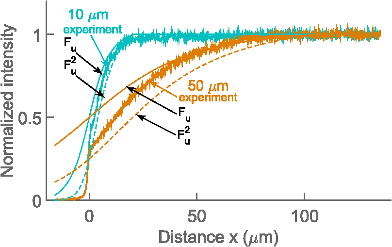 In this largely simplified geometrical model, none of the refracted light rays contributes to the PSF, which leads to large deviations from the experimental data. This error becomes larger with increasing depth , as the fraction of affected light increases. Although this geometrical approach is too simplified to provide an accurate fit for the data, it illustrates the effect of the refractive index on the detected intensity and can identify the distance at which this effect will be observed for each depth . The distorted PSFs were characterized based on acquisition of a -stack of the glass fiber cylinder immersed in an acrylamide gel (10 wt. % acrylamide, 1 mol. % -methylene-bisacrylamide, ) with 170-nm green fluorescent subresolution beads (PS-Speck, P7220, from Invitrogen), using the water immersion lens. The excitation wavelength was 488 nm and the fluorescence detected in the range 500 to 550 nm. The PSFs close to the coverslip (small ) and some distance ( in the range above ) from the fiber were not distorted (images not shown). For the PSF obtained at larger , spherical aberration becomes more severe, particularly in the vicinity of the fiber where the light is refracted and reflected [Fig. 4(c)]. The orthogonal central slice and the -slice show PSF asymmetry and anisotropy. Also, loss in intensity is observed. The PSF far away from the fiber is distorted only in the -direction because of the large imaging depth and slight refractive index mismatch between the sample and the immersion fluid. Fig. 4Fluorescent PSF beads and a glass fiber cylinder immersed in a polyacrylamide gel. (a) The merged CLSM fluorescent and transmission image acquired into the sample using the water immersion lens. The slices in (b) and (c) show the fluorescence of the beads indicated by arrows 1 and 2 in (a), respectively. The -images show the maximum intensity projection (image size ), whereas the and images are slices across the center of the two beads [image size in (b) and for and , respectively, and in (c) and for and , respectively]. The voxel size is .  Due to the presence of the lateral refractive index boundary, the PSF becomes asymmetrical and spatially variant both in the and directions. For the most accurate restoration of the concentration profiles within the image, a deconvolution using spatially variant PSFs should be applied. This is computationally demanding, and current algorithms only employ a -variant PSF.19,20 The available algorithms also restore the total intensity of the images, but they do not compensate for intensity lost outside of the sample volume. Since a significant part of the intensity is permanently lost due to the fiber, these algorithms would not restore the intensity. Deconvolution would also require the knowledge of the PSF at each point in space, either by measuring or by calculating it. However, the PSF becomes complicated as different light rays gain different phase shifts due to the refraction. Salter and Booth21 have suggested a solution to a similar problem in laser manufacturing that consisted of modulating the phase of the laser to restore the PSF to its intended shape and thereby avoid aberration. This approach can also, in principle, be implemented in microscopy to compensate for axial refractive index mismatch, although phase modulation is not readily available for commercial microscopes. In our case, due to the light being refracted twice by the object, the computations become even more complicated. Instead of a deconvolution, we propose to apply an empirical scaling factor to restore the lost intensity although not the resolution. To recover the concentration profiles from a sample image taken in the proximity of an object with different , a reference image is taken of the same object (or similar object with the same geometry and ) in a homogeneous solution. The intensity profile from the reference image is fitted to a suitable function (for simpler geometries, where applicable) or simply smoothed; acquiring a reference profile . The sample profile is then multiplied by the scaling factor to recover the concentration gradients. For the geometries presented here (cuboids and cylinders), the profiles were fitted with a Gaussian curve. The Gaussian was selected because it is the simplest function that adequately describes the experimental data, and causes minimal trends in the residuals as a function of . The fitting function has the following form: where is the intensity at distance along the profile, is the plateau intensity in the unaberrated case, is the height of the peak, is the center of the peak, and gives information about the width of the peak.The adjusted values for each fit were calculated. For cuboid geometries, the values ranged between 0.980 and 0.996, for cylinders between 0.940 and 0.960. For both geometries the values were lower for fitting at , with 0.880 to 0.890. These profiles resemble the step change the most and it is usually not necessary to use the correction for them. In Fig. 5(b) an example of a plot of residuals is shown, with no apparent trends. Fig. 5(a) Experimental fluorescence intensity profiles in the proximity of a vertical glass/solution interface extracted from CLSM images of a glass cuboid () in a homogeneous fluorescent solution (). Normalized detected intensity as a function of distance from the glass/solution interface is shown for NFP at depths varying from (blue) up to (red). Black lines indicating a fitted Gaussian. (b) Plot of residuals as a function of for the fitting of profile at in (a). (c) Experimental fluorescence profile as in (a) and smoothed profiles using a Savitzky–Golay filter. (d) (see text for details) for . (c) for fibers ( for cladding), PDMS () and glass cuboids () at different depths. The markers show the average values of four measurements for fiber and PDMS and two measurements for glass cuboid and the shaded areas depict the standard deviations. The online version depicts the plots in color. 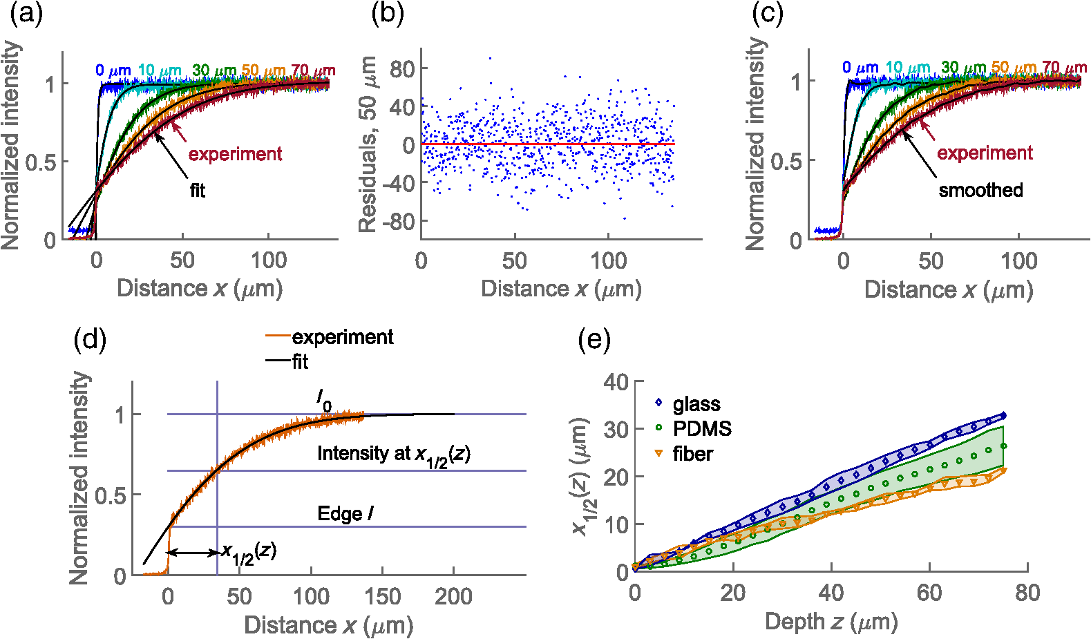 To compare the effects for different materials (different refractive indices ) and different geometries (glass cuboid, end of glass cylinder-fiber) the lateral distance to the half maximum intensity was used. Half maximum intensity [Fig. 5(d)] is the average of the intensity at the boundary and the plateau intensity of the solution in the unaberrated case, located at = distance to half maximum. Figure 5(e) shows the plot of the distance to half maximum intensity for glass cuboids, glass fibers, and PDMS cuboids. The relatively large standard deviations are partly due to the unevenness of the object edges which was largest for the PDMS cuboid. The parameter is larger for glass than for PDMS cuboids at a given which could be due to a larger refractive index difference between the glass and solution than between the PDMS and solution. The parameter for the fiber is expected to differ from that of the cuboid due to the difference in geometry as well as . To test the applicability of the proposed restoration procedure using the scaling factor , several sample objects (Fig. 6) in a homogeneous solution were imaged and intensity profiles from the images were restored using data from reference objects of the same and geometry (in this case the reference object and sample object were not the same). Since the samples were immersed in homogeneous solutions, there is an -independent concentration of the fluorophore which should be recovered by the proposed restoration procedure. The scaling was done using both Gaussian fitting and smoothing with a Savitzky–Golay filter. The restored profiles are nearly constant (Fig. 6), but deviations are observed near the edge of the object. This is mostly due to the restoration process being sensitive to misalignments in the sample and reference image depths, as well as in the -position of the object edge. Both the position of the imaging plane inside the object and the exact position of the edge are difficult to identify precisely due to the blurring at the boundaries, which occurs as a result of the nonzero confocal volume. Fig. 6Fluorescence restoration using Gaussian fitting and smoothing. Examples of unrestored (a–d) and restored (e–h) profiles along the white lines shown in the CLSM image () for different materials (refractive indices indicated) and geometries. The profiles restored using Gaussian fitting are the main ones, while the restored intensities using the smoothing are shown as insets (e–g). (a, e) Glass cuboid, (b, f) PDMS cuboid, (c, g) glass fiber cylinder, and a (d, h) glass fiber with a polyacrylamide PAM hydrogel at its end. Each object is immersed in a homogeneous fluorescent solution (). The intensity profiles at various depths are plotted individually and normalized before correction and after the correction. In the case of the hydrogel, the reference object was a fiber without a hydrogel. Optical effects due to refraction at hydrogel/solution interface were not taken into account. The online version depicts the plots in color.  Figure 6 also shows the restoration procedure applied to a polyacrylamide gel bound to the end of the glass fiber. Here the reference image was of a fiber in a solution only. This means that the refractive index difference for the reference object (fiber/solution) differs from that of the sample object (fiber/gel) and is not accurate. However, the correction still shows that what appeared to be a concentration gradient inside the gel in the initial image is an imaging aberration due to the presence of the fiber. There is also an observed intensity loss in the solution in the proximity of the gel/solution interface. This loss is not corrected for in the restoration procedure, suggesting that a similar aberration process takes place at this interface. Optical aberration occurs whenever light crosses a refractive index boundary. Direct quantitative concentration measurements are impossible near such boundaries due to the observed fluorescence gradient. The extent of this aberration increases with imaging depth (distance from coverslip/sample boundary) and with the proximity to the boundary. While the loss due to aberration is negligible for images recorded close to the coverslip/sample interface, the effect can reduce observed intensity to one-third at larger depths. If it is not possible to image at a sufficient distance from the boundary, we show that using a Gaussian fitting for a reference object allows restoration to recover fluorescence and detect true concentration gradients near simple geometries such as a cuboid or a base of a cylinder. ReferencesD. Fairbairn, K. L. O’Neill and M. D. Standing,
“Application of confocal laser scanning microscopy to analysis of -induced DNA damage in human cells,”
Scanning, 15
(3), 136
–139
(1993). http://dx.doi.org/10.1002/sca.v15:3 SCNNDF 0161-0457 Google Scholar
H. Kawai et al.,
“Direct measurement of doxorubicin concentration in the intact, living single cancer cell during hyperthermia,”
Cancer, 79
(2), 214
–219
(1997). http://dx.doi.org/10.1002/(ISSN)1097-0142 CANCAR 0008-543X Google Scholar
J. W. Lampe et al.,
“Imaging macromolecular interactions at an interface,”
Langmuir, 26
(4), 2452
–2459
(2010). http://dx.doi.org/10.1021/la903703u LANGD5 0743-7463 Google Scholar
A. D. Stroock et al.,
“Chaotic mixer for microchannels,”
Science, 295
(5555), 647
–651
(2002). http://dx.doi.org/10.1126/science.1066238 SCIEAS 0036-8075 Google Scholar
K. Gawel, M. Gao and B. T. Stokke,
“Impregnation of weakly charged anionic microhydrogels with cationic polyelectrolytes and their swelling properties monitored by a high resolution interferometric technique. Transformation from a polyelectrolyte to polyampholyte hydrogel,”
Eur. Polym. J., 48
(11), 1949
–1959
(2012). http://dx.doi.org/10.1016/j.eurpolymj.2012.07.006 EUPJAG 0014-3057 Google Scholar
M. Gao, K. Gawel and B. T. Stokke,
“High resolution interferometry as a tool for characterization of swelling of weakly charged hydrogels subjected to amphiphile and cyclodextrin exposure,”
J. Colloid Interface Sci., 390
(1), 282
–290
(2013). http://dx.doi.org/10.1016/j.jcis.2012.09.020 JCISA5 0021-9797 Google Scholar
A. Egner, S. W. Hell,
“Aberrations in confocal and multi-photon fluorescence microscopy induced by refractive index mismatch,”
Handbook of Biological Confocal Microscopy, 404
–413 Springer, New York
(2006). Google Scholar
S. Hell et al.,
“Aberrations in confocal fluorescence microscopy induced by mismatches in refractive index,”
J. Microsc., 169
(3), 391
–405
(1993). http://dx.doi.org/10.1111/jmi.1993.169.issue-3 JMICAR 0022-2720 Google Scholar
R. Rottenfusser, C. E. Steenerson and M. W. Davidson,
“Focus depth and spherical aberration. Interactive tutorials, basic microscopy,”
(2016) http://www.zeiss.com/microscopy/en_de/solutions/reference/all-tutorials/basic-microscopy/focus-depth-and-spherical-aberration.html December ). 2016). Google Scholar
E. H. Keller,
“Objective lenses for confocal microscopy,”
Handbook of Biological Confocal Microscopy, 145
–161 Springer, New York
(2006). Google Scholar
M. J. Nasse and J. C. Woehl,
“Realistic modeling of the illumination point spread function in confocal scanning optical microscopy,”
J. Opt. Soc. Am. A, 27
(2), 295
–302
(2010). http://dx.doi.org/10.1364/JOSAA.27.000295 JOAOD6 0740-3232 Google Scholar
Y. Deng and J. W. Shaevitz,
“Effect of aberration on height calibration in three-dimensional localization-based microscopy and particle tracking,”
Appl. Opt., 48
(10), 1886
–1890
(2009). http://dx.doi.org/10.1364/AO.48.001886 APOPAI 0003-6935 Google Scholar
A. Diaspro, F. Federici and M. Robello,
“Influence of refractive-index mismatch in high-resolution three-dimensional confocal microscopy,”
Appl. Opt., 41
(4), 685
–690
(2002). http://dx.doi.org/10.1364/AO.41.000685 APOPAI 0003-6935 Google Scholar
H. W. Yoo et al.,
“Automated spherical aberration correction in scanning confocal microscopy,”
Rev. Sci. Instrum., 85
(12), 123706
(2014). http://dx.doi.org/10.1063/1.4904370 RSINAK 0034-6748 Google Scholar
M. J. Booth, M. A. A. Neil and T. Wilson,
“Aberration correction for confocal imaging in refractive-index-mismatched media,”
J. Microsc., 192
(2), 90
–98
(1998). http://dx.doi.org/10.1111/j.1365-2818.1998.99999.x JMICAR 0022-2720 Google Scholar
I. Martinček, I. Turek and N. Tarjányi,
“Effect of boundary on refractive index of PDMS,”
Opt. Mater. Express, 4
(10), 1997
–2005
(2014). Google Scholar
“Concentrative properties of aqueous solutions: density, refractive index, freezing point depression, and viscosity,”
CRC Handbook of Chemistry and Physics, 97th ed.CRC Press/Taylor & Francis, Boca Raton, Florida
(2016). Google Scholar
J. François et al.,
“Polyacrylamide in water: molecular weight dependence of ⟨R2⟩ and [] and the problem of the excluded volume exponent,”
Polymer, 20
(8), 969
–975
(1979). http://dx.doi.org/10.1016/0032-3861(79)90194-0 POLMAG 0032-3861 Google Scholar
S. B. Hadj and L. Blanc-Féraud, Restoration Method for Spatially Variant Blurred Images, 2011). Google Scholar
S. B. Hadj et al.,
“Modeling and removing depth variant blur in 3D fluorescence microscopy,”
in IEEE Int. Conf. on Acoustics, Speech and Signal Processing (ICASSP 2012),
(2012). http://dx.doi.org/10.1109/ICASSP.2012.6287977 Google Scholar
P. S. Salter and M. J. Booth,
“Focusing over the edge: adaptive subsurface laser fabrication up to the sample face,”
Opt. Express, 20
(18), 19978
–19989
(2012). http://dx.doi.org/10.1364/OE.20.019978 OPEXFF 1094-4087 Google Scholar
|


