|
|
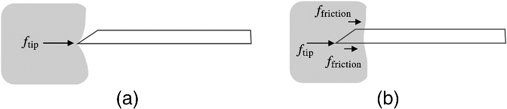
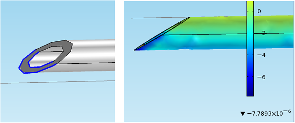
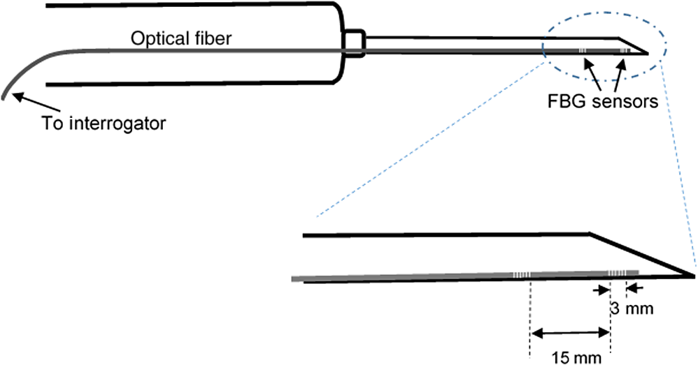
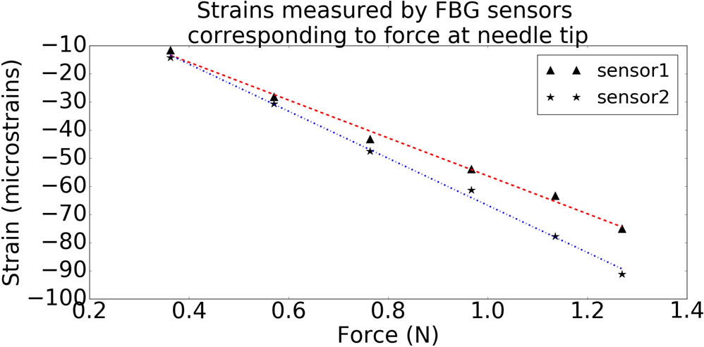
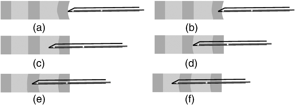
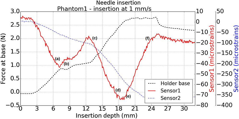
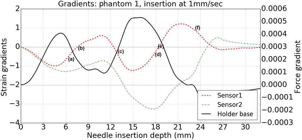
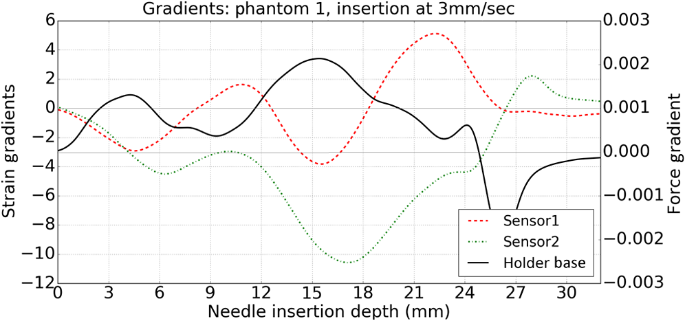
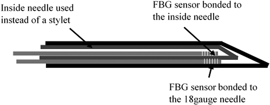
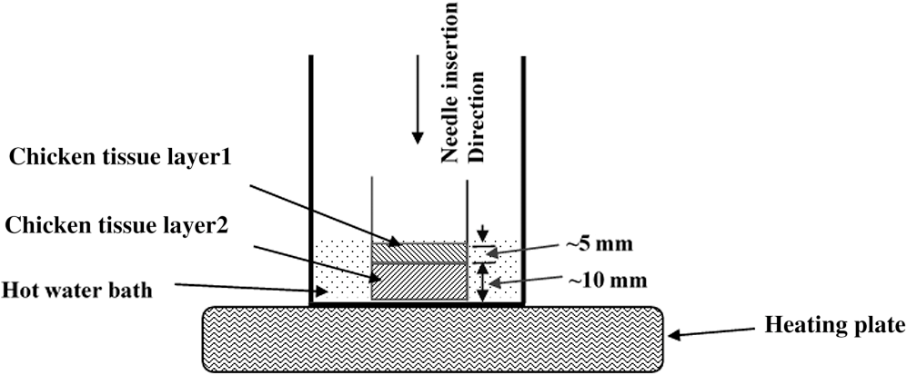
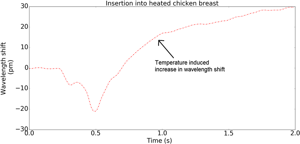
1.IntroductionMedical practices such as biopsy, radiological seed implantation, minimally invasive procedures, and neurosurgery employ needles. With the advancements in the use of robotic and robot assisted procedures, the study of needle–tissue interactions has gained prominence.1–4 Newer procedures, such as natural orifice translumenal endoscopic surgery5–7 which involve indirect manipulation of surgical tools including needles, necessitate both control and haptic feedback. In recent years, a significant part of studies involving needle–tissue interactions has been on solid flexible needles (usually made of Nitinol).8–10 These studies have depended on the measurement of forces at the base of needle holders for all estimations with an aim to create a model for needle–tissue interaction forces based on stiffness, friction, and cutting. The forces acting on a needle can be seen in Fig. 1. The high variations in tissue properties (even for the same organs) make modeling and parameter estimation difficult; the estimated forces using models have high variations compared to forces measured at the needle holder base and the sources of error are difficult to isolate.11,12 These studies have been supplemented by studies involving the estimation of needle deflection for flexible needles. Fiber Bragg grating (FBG) sensors have been used to estimate the shape of the flexible needle by bonding sensors into grooves made in the needle.13–18 A sensing mechanism close to the needle tip can be advantageous compared to measuring the forces at the needle holder base considering the high variability in stiffness and frictional forces as well as varying tissue deflections. Since the mechanical properties of tumors differ from a healthy tissue, observing small localized changes can be useful. This can get lost when other variabilities like frictional forces are involved. Also, in endoscopic procedures, it is difficult to measure the forces at the needle holder base. In this paper, we extend our previous work19 toward estimating the needle–tissue interaction forces using FBG sensors. The experiments have been restricted to hollow needles. 2.Materials and Methods2.1.Needle and Sensor CharacteristicsThe most important parameters to consider for hollow needles are the needle diameter and needle tip geometry. For example, most prostrate brachytherapy needles are 18-G needles that have an outer diameter of 1.27 mm. The common commercially available needles have variations of bevel shaped cutting tips (e.g., brachytherapy and spinal needles) and symmetrical multiplane cutting tips (e.g., Franseen needles used in lung biopsy) as shown in Fig. 2. An 18-G bevel tipped needle (Quincke)20 has been used for the experiments. Before deciding on placement of sensors, finite element method (FEM) simulation has been performed using an approximate model in COMSOL and applying a fixed load at the cutting edge of the needle as shown in Figs. 3 and 4. This is done to check if the amount of strain that would be encountered along the axis of the needle can be measured using the sensing setup. In the simulation results, as shown in Fig. 4, for a load of 0.1 N applied axially at the tip, a strain of approximately five microstrains has been observed at regions 1 to 2 mm away from the tip along the axis. Fiber optic sensors including FBG sensors and long period grating sensors have been extensively used in structural health monitoring21,22 and biomedical applications.23 FBG sensors are optical sensors created by a periodic refractive index modulation in the core of an optical fiber.24 The Bragg wavelength , which is the peak wavelength reflected by the sensor, is a function of the grating pitch and the effective refractive index as follows: where is the effective refractive index and is the grating pitch. The sensing principle is based on the change in Bragg wavelength due to change in grating pitch and the effective refractive index in response to a physical phenomenon as follows: where is the change in temperature and is the change in length.21For constant temperature, the response can be reduced to where is the photoelastic constant and is the longitudinal strain.The strain of five microstrains for a 0.1 N load as seen in the simulation results corresponds to a wavelength shift of 3.94 pm. This can be easily detected by the FBG interrogation systems used in the present experiments (SM130 from Micron Optics and IMON-512 from Ibsen Photonics). FBG sensors were fabricated in a germanosilicate optical fiber (Nufern) using the phase mask method.25 The phase mask method provides high repeatability and control on the Bragg wavelength. However, one challenge with the method is replacement of phase masks for fabricating sensor arrays. Two sensors close to each other were fabricated using prestretching of the fiber for the second sensor and translating the fiber as shown in Fig. 5. This allowed easy fabrication of sensors with a Bragg wavelength separation in the range of 1.5 to 2 nm. Fig. 5Sensors fabrication (a) first sensor fabricated with no stretching and (b) second sensor by translating the fiber and prestretching. 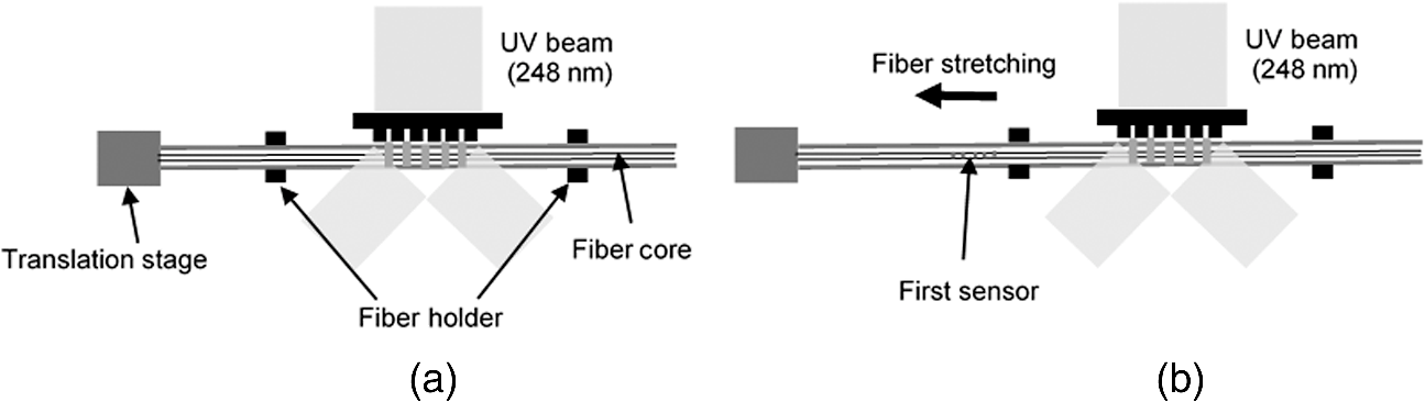 The FEM simulations as well as initial experiments carried out indicate that the difference in the strain observed at points close to each other along the needle axis is small. Hence, this wavelength separation is sufficient. The gauge length of each sensor is 3 mm and the separation between the two sensors is about 1.5 cm. The fiber is bonded inside the needle lumen along the axis as shown in Fig. 6. 2.2.Needle Insertion SetupA test setup has been designed for the controlled needle insertion and to compare forces measured by the two FBG sensors in correspondence with the forces at the needle holder base during the needle insertion into tissue-phantoms. It consists of a linear actuation assembly, a force sensor, a displacement sensor and needle, and tissue-phantom holders as shown schematically in Fig. 7. The linear actuation is controlled manually or programmed for specific insertion distances at varying speeds through a programmable logic controller. An S-type strain gauge fixed to the needle holder assembly measures the forces with a resolution of 1 mN with a range of 0 to 10 N. A syringe with the instrumented needle is rigidly fixed to the holder. A linear variable displacement transformer is used as an absolute position sensor. The tissue mimicking phantoms are contained in a plastic tube rigidly held in the specimen holder. This is required to prevent the phantom from moving along with the needle during insertion. 2.3.Polydimethylsiloxane PhantomPolydimethylsiloxane (PDMS) is a silicone-based polymer. It is optically clear which has led to its usage as a tissue mimicking phantom in optical coherence tomography.26,27 Another major advantage is the ability to vary its mechanical properties in a controlled manner by varying the cross linking. Hence, it has also been used in studies related to impact response of biological tissue.28 The phantom is stable over longer duration and can be easily stored at room temperature. It can be easily used at temperatures around 37°C to 40°C, which is the usual range of body temperature without problems related to loss of water and major changes in mechanical properties as observed with gelatin-based phantoms at such temperatures. The Sylgard 184 silicone elastomer kit has been used for preparing the phantoms. It consists of a base elastomer and a curing agent. For all experiments, phantoms have been prepared using base polymer to curing agent ratios of 10:0.6 and 10:0.4 and curing at 80°C. 3.Measurements and Results3.1.Sensitivity DeterminationIn order to determine the sensitivity of the instrumented needle to external forces, calibration has been performed by applying small external loads at the needle tip and simultaneously measuring the strains measured by the two FBG sensors. The response obtained is linear as shown in Fig. 8 and the sensitivity of the two sensors is obtained from the slope of a linear least square fit to the data points. Both loading and unloading experiments have been performed and no hysteresis effects have been observed. The experiments have been repeated in the limit of 0 to 1.4 N external forces at the tip and no nonlinear effects are seen. The sensitivity of FBG sensor 1 (closer to the tip) obtained is and that of FBG sensor 2 is . The reason for difference in sensitivity is the slight bending at the tip at higher loads, which acts against compression. 3.2.Transition through Layers with Different StiffnessSince tumors can have a higher stiffness than healthy tissue,29 one of the goals in needle penetration estimation is to determine transition from a layer of lower stiffness to a layer of higher stiffness followed by transition to a layer of lower stiffness. This includes transition estimation when the needle tip is already surrounded by tissue and hence the frictional forces are acting on the needle. To analyze the effectiveness of using force measurements at the tip for this situation, phantoms with five layers have been created using PDMS by varying the ratio of base polymer to curing agent as shown in Fig. 9. The higher stiffness layer is created using a base polymer to curing agent ratio of and the lower stiffness layer is created using a ratio of . The phantom is created by adding layers one at a time. The second layer is added after partial curing of the first layer and so on. This method enables creation of multilayered PDMS phantoms without the need for plasma treatment of layer surfaces. The phantom is prepared inside a plastic tube with sealing at one end to avoid motion of the phantom during needle insertion. The needle insertion is made at 1, 2, 3, and from the layer with higher stiffness toward the next layers as shown in Fig. 10 and the strain responses of the two sensors are recorded along with the needle displacement and force at the needle holder base. The response of the two FBG sensors during transition through different layers is shown in Fig. 11. An important point to consider is the deformation of the phantoms during insertion. The presence of alternative layers with higher and lower stiffness also leads to varying amounts of deformation at different stages of insertion. This is reflected in the graph of Fig. 11. Hence, the points at which transitions occur do not match exact boundaries as shown in Fig. 9. The deformation of the first layer is significantly higher than that of the third layer. The deformations also vary slightly with insertion velocity. In order to analyze and use the response, it is required to find the features in the signal that can be reliably used to determine transitions between layers in spite of variation in needle insertion speed and depth of insertion. Gradients are one such feature. Figure 12 shows the gradient of the strains and the force at the needle holder base computed using the central difference method. The gradients show that sensor one (closer to the needle tip) responds faster during the transition between layers. Another advantage of using the gradient of strains measured by sensor one is the zero crossing of the gradients. These are the points where the needle tip moves inside the layers with higher stiffness (points “b” and “e”) after rupture leading to a reduction of strains for a small insertion distance. The effect of deformation is evident by comparing the initial boundaries of the layers in Fig. 9 and the points “b” and “e” in Fig. 11. Using the gradient allows the identification of transitions without depending directly on the knowledge of the thickness of the layers or on the estimation of the deformation and the subsequent relaxation. The forces are known to vary even for the same tissues for varying insertion rates.12 Hence, it is important to show that the use of gradients is valid for varying needle insertion rates. The strains and the gradients for insertion at can be seen, respectively, in Figs. 13 and 14. It can be seen that the gradients of strains measured by sensor 1 still show a similar pattern and can be used to identify the transitions. The response of the sensors for all four needle insertion rates and for both phantoms can be seen in Figs. 15 and 16, respectively. These figures show that the nature of response is similar across needle insertion rates and phantoms with varying thickness of the layers. The small variations in first transition point based on insertion velocity can also be seen. Fig. 15Strains measured by the two FBG sensors and force measured at the needle holder base for insertion in phantom 1 at varying needle insertion rates. 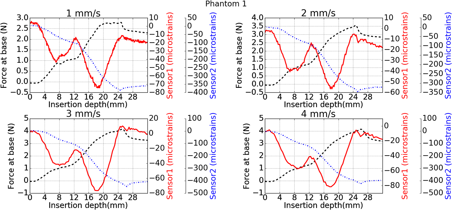 Fig. 16Strains measured by the two FBG sensors and force measured at the needle holder base for insertion in phantom 2 at varying needle insertion rates.  The measurements show that absolute values of the strains and forces vary across insertion velocities and phantoms. However, the trends in variation in strains remain the same. These trends are reflected in the gradients which in turn follow similar patterns and can be used for transition estimation. 3.3.Temperature CompensationFor experiments using phantoms, there is no temperature change during needle insertion. However, during insertion in real tissue, there can be slight variations in the temperature. Hence, compensation is required to handle the FBG sensor’s cross sensitivity to temperature. This is achieved by using the configuration as shown in Fig. 17. A needle stylet is a solid rod inserted in the needle lumen to prevent any occlusion during insertion. In the modified design used for temperature compensation, the solid stylet has been replaced by a hollow needle with a sealed tip. Another fiber with an FBG sensor is bonded close to the tip inside this needle. The outer diameter of this needle is chosen close to the inner diameter of the actual needle. During insertions, no strain is induced on this FBG sensor. However, since it is located at the same place as the FBG sensor 1, it responds to any temperature changes. This enables the elimination of cross sensitivity to temperature. Temperature sensitivity of a 1550-nm FBG sensor in a germanium doped silica core fiber is .24 The temperature response of the two sensors has been analyzed by placing the needle on a controlled heating plate and applying a step change from 36°C to 38°C. The temperature of the hot plate rises gradually and then settles around the final value. The temperature value is chosen closer to the usual temperature of the human body. The response of the two sensors is as seen in Fig. 18. The slightly higher settling point for a 2°C change is because of the fact that the final temperature of the heating plate slightly overshoots 38°C due to inaccuracies in the control method. During the period in which temperature is rising, the maximum error between the actual sensor on the 18-G needle and the compensation sensor in the inside needle is 6 pm and the average error is 3.5 pm. Since the wavelength shifts due to strain during needle insertion are much higher and strain variations are much faster, the compensation can be used to account for changes in temperature. 3.4.Insertion in Heated Chicken TissueTo validate that the temperature compensation works in real tissue, insertions have been made in chicken tissue that has been heated using the setup as shown in Fig. 19. The purpose of heating the chicken tissue is to create a temperature gradient. The response of the senor bonded on the 18-G needle is shown in Fig. 20. The effect of temperature can be clearly seen as the wavelength shift is positive and it continues to rise because of the temperature till it reaches the settling point. If temperature effect is not compensated, it would appear as a response to an axial force causing elongation instead of compression of the needle during insertion. The response of the FBG sensor bonded on the measurement needle (18 G) and of the FBG sensor on the inside needle, which acts as the stylet, can be seen in Fig. 21(a). It can be observed that the sensor on the inside needle responds only to the temperature change. This allows to compensate for temperature-induced effects on the measurements by the 18-G needle which measures both temperature and strain-induced effects during insertion. This can be done by subtracting the response of the sensor on the inside needle from that of the sensor on the 18-G needle. The compensated response is as shown in Fig. 21(b). Fig. 21(a) Response of the sensor bonded to the 18-G needle and that to the inside needle during insertion in heated tissue and (b) the temperature compensated response of the sensor bonded to the 18-G needle. 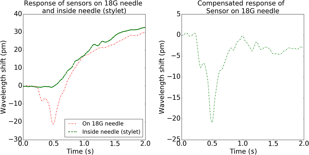 The gradients of the strain response after applying temperature compensation have been plotted in Fig. 22 to compare with those obtained using the insertions in the PDMS phantoms. The point before needle puncture (a) and the point when the needle punctures the first layer and goes inside tissue (b) can be identified in the gradients. The movement inside the tissue (c) and transition inside the second layer (d) can also be seen. 4.Conclusion and Future WorkThe results from the experiments show that it is possible to detect the different stages of needle penetration using FBG sensors placed close to the needle tip. The advantages of the small sensor size and high sensitivity are evident. The use of gradients of the strain measured by sensor 1 in the experiments provides a means to determine the transitions without use of exact thresholds and slopes. It also overcomes the challenges posed by the variation in absolute values and the rates of changes of strains for insertions at varying rates. This would allow its usage in flexible instruments without the need of force measurements at the needle holder base. This would also enable us to develop assistive systems for procedures that involve precise positioning of needles beyond certain organ or tissue boundaries. In the future, it is planned to repeat the measurements for a needle attached to an endoscope and estimate transitions for insertions in which the rate or insertion is not constant. This is challenging as it would also require simultaneous estimation of linear translation of the needle at the tip of the endoscope which is different from that at the end outside the body. It is also envisaged to extend this work to estimate the deflection of the phantoms and tissues as well as relaxation after insertion. This can be beneficial for procedures like brachytherapy in which multiple needle insertions are made and accuracy can be improved by estimating the tissue relaxation after radioactive seed implantation. DisclosuresThe authors declare that they do not have any conflict of interest, financial or otherwise. AcknowledgmentsWe would like to acknowledge the help provided by Dr. Ravi Nayar, Center for Academic Research at H.C.G. Hospital, Bangalore, India, for valuable discussions, and also acknowledge the support in the form of funding by Robert Bosch Centre for Cyber Physical Systems at Indian Institute of Science, Bangalore. ReferencesR. Alterovitz et al.,
“Needle insertion and radioactive seed implantation in human tissues: simulation and sensitivity analysis,”
in Proc. of IEEE Int. Conf. on Robotics and Automation,
1793
–1799
(2003). http://dx.doi.org/10.1109/ROBOT.2003.1241854 Google Scholar
G. Wan et al.,
“Brachytherapy needle deflection evaluation and correction,”
Med. Phys., 32
(4), 902
–909
(2005). http://dx.doi.org/10.1118/1.1871372 MPHYA6 0094-2405 Google Scholar
S. E. Salcudean et al.,
“A robotic needle guide for prostate brachytherapy,”
in Proc. of IEEE Int. Conf. on Robotics and Automation,
2975
–2981
(2008). http://dx.doi.org/10.1109/ROBOT.2008.4543662 Google Scholar
M. Mahvesh and P. E. Dupont,
“Mechanics of dynamic needle insertion into biological material,”
IEEE Trans. Biomed. Eng., 57
(4), 934
–943
(2010). http://dx.doi.org/10.1109/TBME.2009.2036856 IEBEAX 0018-9294 Google Scholar
I. Halim and A. Tavakkolizadeh,
“NOTES: the next surgical revolution?,”
Int. J. Surg., 6 273
–276
(2008). http://dx.doi.org/10.1016/j.ijsu.2007.10.002 Google Scholar
S. Gillen et.al.,
“Natural orifice transluminal endoscopic surgery in pancreatic diseases,”
World J. Gastroenterol., 16
(31), 3859
–3864
(2010). http://dx.doi.org/10.3748/wjg.v16.i31.3859 Google Scholar
C. F. Granberg and M. T. Gettman,
“Instrumentation for natural orifice transluminal endoscopic surgery and laparoscopic single-site surgery,”
Indian J. Urol., 26
(3), 385
–388
(2010). http://dx.doi.org/10.4103/0970-1591.70577 Google Scholar
A. Majewicz et al.,
“Evaluation of robotic needle steering in ex vivo tissue,”
in Proc. of IEEE Int. Conf. on Robotics and Automation,
2068
–2073
(2010). http://dx.doi.org/10.1109/ROBOT.2010.5509873 Google Scholar
K. B. Reed et al.,
“Robot assisted needle steering,”
IEEE Rob. Autom Mag., 18
(4), 35
–46
(2011). http://dx.doi.org/10.1109/MRA.2011.942997 IRAMEB 1070-9932 Google Scholar
S. Badaan et al.,
“Does needle rotation improve lesion targeting?,”
Int. J. Med. Rob. Comput. Assisted Surg., 7
(2), 138
–147
(2011). http://dx.doi.org/10.1002/rcs.381 Google Scholar
A. M. Okamura, C. Simone and M. D. O’Leary,
“Force modelling for needle insertion into soft tissue,”
IEEE Trans. Biomed. Eng., 51
(10), 1707
–1716
(2004). http://dx.doi.org/10.1109/TBME.2004.831542 IEBEAX 0018-9294 Google Scholar
D. J. Gerwen, J. Dankelman and J. J. Dobbelsteen,
“Needle-tissue interaction forces—a survey of experimental data,”
Med. Eng. Phys., 34 665
–680
(2012). http://dx.doi.org/10.1016/j.medengphy.2012.04.007 Google Scholar
Y. L. Park et al.,
“Real-time estimation of 3-D needle shape and deflection for MRI guided interventions,”
IEEE/ASME Trans. Mechatronics, 15
(6), 906
–915
(2010). http://dx.doi.org/10.1109/TMECH.2010.2080360 IATEFW 1083-4435 Google Scholar
M. Abayazid, M. Kemp and S. Misra,
“3D flexible needle steering in soft-tissue phantoms using fiber Bragg grating sensors,”
in Proc. of IEEE Int. Conf. on Robotics and Automation,
5843
–5849
(2013). http://dx.doi.org/10.1109/ICRA.2013.6631418 Google Scholar
R. J. Roesthius et al.,
“Three-dimensional needle shape reconstruction using an array of fiber Bragg grating sensors,”
IEEE/ASME Trans. Mechatronics, 19
(4), 1115
–1126
(2014). http://dx.doi.org/10.1109/TMECH.3516 IATEFW 1083-4435 Google Scholar
K. R. Henken et al.,
“Error analysis of FBG-based shape sensors for medical needle tracking,”
IEEE/ASME Trans. Mechatronics, 19
(5), 1523
–1531
(2014). http://dx.doi.org/10.1109/TMECH.2013.2287764 IATEFW 1083-4435 Google Scholar
A. Jahya, F. van der Heijden and S. Misra,
“Observations of three-dimensional needle deflection during insertion into soft tissue,”
in IEEE RAS/EMBS Int. Conf. on Biomedical Robotics and Biomechatronics,
(2012). http://dx.doi.org/10.1109/BioRob.2012.6290756 Google Scholar
H. Sadjadi, K. Hashtrudi-Zaad and G. Fichtinger,
“Fusion of electromagnetic trackers to improve needle deflection estimation: simulation study,”
IEEE Trans. Biomed. Eng., 60
(10), 2706
–2715
(2013). http://dx.doi.org/10.1109/TBME.2013.2262658 IEBEAX 0018-9294 Google Scholar
S. Kumar et al.,
“Estimating needle-tissue interaction forces for hollow needles using fiber Bragg grating sensors,”
Proc. SPIE, 9702 97020T
(2016). http://dx.doi.org/10.1117/12.2212595 PSISDG 0277-786X Google Scholar
N. Calthorpe,
“The history of spinal needles: getting to the point,”
Anaesthesia, 59 1231
–1241
(2004). http://dx.doi.org/10.1111/ana.2004.59.issue-12 Google Scholar
S. Zheng,
“Long-period fiber grating moisture sensor with nano-structured coatings for structural health monitoring,”
Structural Health Monitoring, 14
(2), 148
–157
(2015). http://dx.doi.org/10.1177/1475921714560069 Google Scholar
J. M. Ko and Y. Q. Ni,
“Technology developments in structural health monitoring of large scale bridges,”
Eng. Struct., 27
(12), 1715
–1725
(2005). http://dx.doi.org/10.1016/j.engstruct.2005.02.021 ENSTDF 0141-0296 Google Scholar
S. Umesh and S. Asokan,
“A brief overview of the recent bio-medical applications of fiber Bargg grating sensors,”
J. Indian Inst. Sci., 94
(3), 319
–328
(2014). JIISAD 0970-4140 Google Scholar
K. O. Hill and G. Meltz,
“Fiber Bragg grating technology fundamentals and review,”
J. Lightwave Technol., 15
(8), 1263
–1276
(1997). http://dx.doi.org/10.1109/50.618320 JLTEDG 0733-8724 Google Scholar
A. Othonos and K. Kalli, Fiber Bragg Gratings–Fundamentals and Applications in Telecommunications and Sensing, 95
–99 Artech House, London
(1999). Google Scholar
F. Ayers et al.,
“Fabrication and characterisation of silicone-based tissue phantoms with tunable optical properties in the visible and near infrared domain,”
Proc. SPIE, 6870 687007
(2008). http://dx.doi.org/10.1117/12.764969 Google Scholar
G. Lamouche et.al.,
“Review of tissue simulating phantoms with controllable optical, mechanical and structural properties for use in optical coherence tomography,”
Biomed. Opt. Express, 3
(6), 1381
–1398
(2012). http://dx.doi.org/10.1364/BOE.3.001381 BOEICL 2156-7085 Google Scholar
Z. I. Kalcioglu,
“Tunable mechanical behavior of synthetic organogels as biofidelic tissue stimulants,”
J. Biomech., 46 1583
–1591
(2013). http://dx.doi.org/10.1016/j.jbiomech.2013.03.011 JBMCB5 0021-9290 Google Scholar
V. Jalkanen et al.,
“Prostate tissue stiffness as measured with a resonance sensor system: a study on silicone and human prostate tissue in vitro,”
Med. Biol. Eng. Comput., 44 593
–603
(2006). http://dx.doi.org/10.1007/s11517-006-0069-6 MBECDY 0140-0118 Google Scholar
|