|
|
1.IntroductionThere are several imaging modalities being studied to guide surgical oncology.1–19 Confocal microscopy is an emerging technology for rapid imaging of freshly excised tissue without the need for frozen- or fixed-section processing. Initial studies have described the major findings of invasive breast cancers using fluorescence confocal microscopy. However, the regions of interest (ROIs) used in the analysis were user-selected and small (typically ). Although these important findings open exploration into rapid pathology, integrating confocal microscopy into a pathology reading setting will require examination of large specimens in a blinded fashion. Typically, pathologists initially inspect the entire pathology section with low magnification objective lens and then zoom in to ROIs with higher magnifications to closely investigate suspected regions. In this study, we present the development and testing of an emulated pathology examination-like approach and exploration with a microscope, termed the confocal strip-mosaicking microscope (CSM microscope), which images an area of of tissue with cellular-level resolution in 10 min of excision. Confocal microscopy provides images of fresh tissue with noninvasive optical sectioning of 1 to [depending on the illumination wavelength, objective lens, and detection (pinhole) aperture parameters] and with lateral resolution in the order of . However, the field of view (FOV) is small () compared to the typical size () of breast specimens such that individual images allow examination of only small areas within a whole specimen. Several groups, including our group, have developed techniques to generate large FOVs with mosaics of individual images so that entire specimens can be visualized. In dermatological settings, for example, confocal mosaicking technology is being implemented for the detection of residual basal cell carcinoma margins to guide Mohs surgery of skin.20–23 Dobbs et al.7 conducted an initial study to evaluate the usefulness of confocal microscopy for breast specimens. In this study, the mosaics (composite confocal images) were compared to the hematoxylin and eosin (H&E)-stained sections, and single images of ROIs in size were extracted for evaluation by the reader (pathologist). Only the ROIs that matched the architecture in both H&E and confocal images were subjected to the analysis. This study was an important step toward exploration of rapid pathology to guide surgery. Beyond this study, the next required advance is to emulate workflow in a typical pathology setting where the pathologist views the entire tissue section at low magnification and then zooms in on the suspected ROI. The need to evaluate entire tissue specimens has generated interest in exploring imaging and mosaicking techniques on fresh tissue and the performance of such techniques for rapid pathology evaluation. Emerging rapid pathology techniques must emulate current examination techniques of pathology slides where the tissue section is initially inspected with a low magnification objective lens and then zoomed in to ROIs with higher magnifications using objective lenses of to magnification. Our approach with the current prototype CSM microscope provides an FOV of up to . We briefly describe the CSM microscopy technique in Sec. 2 and point the reader to our previous publications for a more detailed description.24,25 The basic idea of a mosaicking microscope is to generate a mosaic from individual high-resolution images. The CSM microscope acquires long strip images and stitches the image strips to complete the mosaic. The current prototype CSM microscope is capable of producing an image of tissue in less than 5 min once the specimen is mounted on the microscope. The total time from tissue extraction to staining with a nuclear contrast agent and scanning to produce a mosaic is . Because the images are acquired with cellular-level resolution, the pathologist can zoom in and zoom out to observe the tissue with different magnifications, similar to the use of low and high magnifications when examining frozen or fixed sections for histopathology under a wide-field microscope. Both CSM instrumentation and methods, including initial imaging test experiments on breast tissue, are described in detail in our earlier publications.24 Following the initial experiments, we conducted a study to test the imaging on specimens as large as those that are routinely used for conventional pathology, followed by analysis of the mosaics against the corresponding H&E histopathology for concordance and discordance. Here, we present the results of our investigation of assessment of 34 fresh breast tissue specimens using the CSM technique where the pathologist has access to the whole view of the tissue and quickly focus on areas of interest—a compatible practice to that when pathologists view H&E-stained slides. 2.MethodsUnder a protocol that was approved by the institutional review board of Memorial Sloan Kettering Cancer Center (MSKCC), a total of 117 breast tissue specimens obtained from surgical excisions and mastectomy specimens from 50 patients were imaged. Of these, 83 specimens were used to complete the development and testing the microscope and the methods beyond the initial work that was reported earlier.24 There are multiple factors in the technique, such as the leveling mechanism (described below), applying correct pressure on the tissue, using proper overlap in the stitching algorithm to remove vignetting effects, and containing the specimen in the scanning FOV, involved in producing confocal mosaics of large areas () of fresh tissue. Because the CSM microscope is an experimental laboratory instrument, during the early development stage of the microscope it was difficult to achieve all the factors in every imaging session. This produced images that were not suitable to include in the study. We used the following criteria to select images for evaluation:
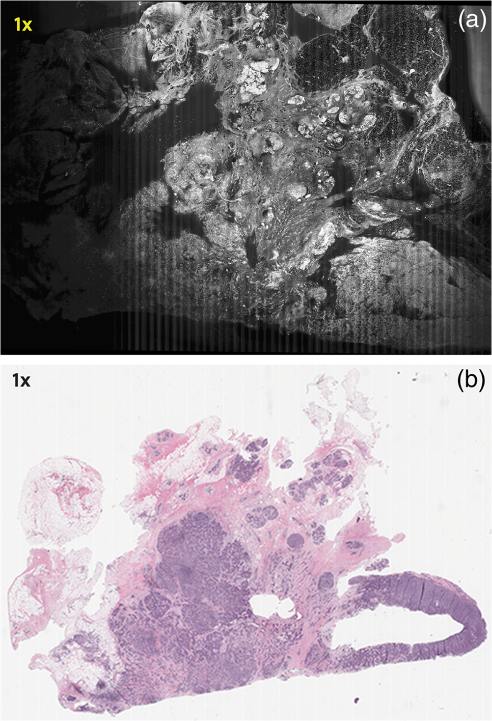
Subsequently, mosaics of the remaining 34 fresh specimens from 18 patients collected were assessed for this study. Each specimen, typically 15- to 20-mm long and wide, was immersed in 0.6 mM acridine orange (AO) (a fluorescent dye that labels the nucleus) for 45 s, placed on the optical coverglass window of the CSM microscope, and scanned with a 488-nm laser. Each scan produced an image of 0.5-mm wide by the length of the sample. The images consist of measured values of lateral resolution and optical sectioning. Image strips were acquired and they were merged (stitched) along the length of the strip to create a seamless mosaic of the entire tissue specimen. The CSM microscope can currently produce mosaics that display specimen in 90 s and specimen in less than 5 min after the tissue is mounted on the CSM microscope. In addition to the unique design of the microscope to acquire confocal image strips, there are two other components that are necessary for successful imaging of large tissue specimens. These two components are the tissue holder and the leveling mechanism. 2.1.Confocal Strip-Mosaicking MicroscopeThe strip mosaicking scheme is shown in Fig. 1. It employs a fast scan by a polygon in the -direction and the slower scan by a stage in the -direction. The fast scanner produces a laser line (in the -direction) that defines the width of a strip. The sample is translated orthogonally to the laser line (in the -direction) by the stage. For a 10-mm-long strip, the aspect ratio of the resulting image strip is . To scan the first strip, the stage translates the sample in -direction. Once strip 1 is completed, the stage moves in the -direction, a distance less than the width of the strip. The stage then moves in the return scan direction to complete the next strip. This process is repeated until the entire tissue is imaged. Because the -direction movement is less than the width of a strip, strips are overlapped (shown in gray in Fig. 1) with adjacent strips. The overlap is of the width and used as a parameter in the stitching algorithm. Fig. 1Schematic depicting of the CSM mechanism. A laser spot (blue circle) is scanned in -direction by a polygon creating laser lines (blue lines). The scan length of the laser spot sets the width of a strip. The sample is translated orthogonal to the laser line in - and -directions to create image strips. Once the scan of an image strip is completed, the sample is displaced in -direction, a distance less than the width of the strip. This leaves overlap between any two strips (depicted in gray). Image strips covering the entire sample are collected.  The advantages of the strip mosaic method over the traditional square FOV mosaics are threefold. First, because the stage motor is run continuously along a strip instead of starting and stopping between each image acquisition, the total time for image acquisition is decreased by approximately a factor of 2. Second, the one-dimensional optical scan has intensity falloff along only one dimension, whereas the two-dimensional optical scan results in intensity falloff along both scan directions in the image, which makes image correction more complicated. Third, in the square mosaic, each successive square image must be registered to two previous images, which increases computing complexity and therefore time, and where errors in image alignment in a previous row can have a detrimental effect on registration of images in the following row. In the strip mosaic, each strip is stitched to only the preceding strip, and there is no compounding of errors. 2.2.Tissue HolderA critical component of mosaicking on large areas is to ensure that the fresh tissue specimen surface is flush with the coverglass window at the interface. Any microscopic space between the coverglass window and the specimen blurs the image. We developed several mechanisms to press tissue against the coverglass window and these methods have been described in our previous publications.26 Because the tissue architecture and density differ from organ to organ, a tissue holder for breast tissue was designed and developed. Breast tissue is typically fatty and soft and when pressed against a coverglass window, it tends to slide out of position. We designed a holder that encapsulates the tissue before applying pressure so that the breast specimen is held in place without sliding (Fig. 2). Another consideration was applying the correct amount of pressure so that breast tissue is flattened onto the coverglass window while minimizing tissue distortion. This challenge is further elaborated in detail in Sec. 4. Fig. 2A schematic of the breast tissue holder, before applying pressure on the sample. The tissue holder consists of a chamber filled with water and a piston. The chamber has a rigid body housing (outlined in green) that is connected to an elastic bladder (outlined in orange). The coverglass secures onto the rigid housing of the chamber. When the piston is retracted, the elastic membrane sinks into the water chamber. To flatten the sample onto the coverglass, we first retract the piston to create a concaved space, and then secure the coverglass with the sample to the housing. Once the coverglass is secured, we insert the piston down to apply pressure on the sample. Because pressure is applied homogeneously on the bladder, the concave dome encapsulates the tissue in place and applies pressure to flatten the sample.  2.3.Leveling MechanismCSM microscope images are . The microscope has lateral resolution and depth resolution (optical sectioning). The requirement for imaging a selected -thin optical section on the sample is that the tissue–coverglass–window interface must be parallel to the focal plane of the optics in the entire scanning area. The schematic in Fig. 3 is used to illustrate the planes orientation. Misalignment in these two parallel planes leads to dark and blurred regions in a mosaic. Parallelizing the two planes requires careful alignment using CSM’s leveling mechanism before a specimen is scanned. Fig. 3Schematic showing the orientation of tissue–coverglass–window interface (depicted with dashed-red line) and the focal plane (dashed-turquoise line). The picture on the left illustrates the case of unparallel planes and the picture on the right illustrates the parallel case. The angle between the tissue–coverglass–window and the focal plane is exaggerated in the illustration for visual clarity. The focal plane is perpendicular to the optical axis of the microscope. The objective lens and the laser focal spot are stationary while the sample is scanned back and forth over the laser focal spot (scanned direction is shown with the double-headed chartreuse arrow). When the two planes are not parallel to each other the laser focal spot is outside the desired tissue section. When the planes are parallel, the laser focal spot remains on the tissue.  2.4.Sample Preparation and ImagingThe tissue specimens were kept moist in isotonic phosphate-buffered saline (PBS) until they were imaged. Tissue specimens were submerged in 0.6 mM AO for 45 s and rinsed twice in two fresh PBS baths for 30 s each time. The specimen was mounted on the coverglass window and imaged. A total of 34 tissue specimens were collected from female patients including 8 invasive carcinomas, 3 ductal carcinoma in situ (DCIS), and 23 benign breast tissue specimens. CSM images were acquired sequentially in two modes of contrast: exogenous fluorescence with AO staining which highlights the nuclei, comparable to staining with hematoxylin, and endogenous reflectance which highlights the stroma, comparable to the staining with eosin. Specimens were subsequently fixed in formalin and processed to obtain routine H&E-stained sections. The H&E-stained sections and CSM images were compared by our pathologist (M.P.M). The images were displayed on a 30-in. HP ZR30w LCD monitor with pixilation of . The full CSM image was initially followed by digitally zooming in at low magnification (corresponding to magnification of , as is performed when examining pathology) on ROIs. The ROI was further investigated by zooming in at higher magnifications to analyze cytological details and microstructures. A side-by-side comparison between CSM images and histopathology was performed to analyze the correlation (by M.P.M). The images were evaluated for the presence of invasive carcinoma, DCIS, and benign breast parenchyma. 3.ResultsThe 34 mosaics that were created for comparison to histology demonstrate reproducibility of the tissue fixturing and mosaicking algorithm. Lateral registration between the edges of images was observed to be subpixel. The majority of the mosaics appear seamless and contiguous with high-resolution and uniform illumination over large areas of tissue and are useful for clinical visualization and comparison to histology. The image quality of the mosaics is reproducible for examination of the gross morphology and cytologic detail in the majority of cases. The fluorescence signal and visual contrast of nuclear staining are acceptable as qualitatively and independently assessed by our pathologist (M.P.M). The artifacts on the borders of image mosaics were negligible and not distracting in more than 90% of the mosaics. (We realize that whether an artifact is perceived as “distraction” is dependent on the image reader.) Viewing mosaics at low magnification, equivalent to viewing with a objective lens on a standard pathology microscope showed good resolution and contrast and was usually sufficient to readily detect and distinguish invasive and in situ carcinoma from benign breast tissue. 3.1.Concordant CasesOf the 34 tissue specimens that were mosaicked, concordance was seen in 30. Invasive carcinomas are identified in the CSM images and correlate with the H&E-stained section from the formalin-fixed paraffin-embedded (FFPE) tissue. The size and shape of the invasive tumor match the histopathology, and the interface of the invasive carcinoma and surrounding adipose tissue can be accurately outlined (Figs. 4 and 5). Nuclei are seen as bright ovals in the fluorescence image [Fig. 5(a)] corresponding to purple-stained nuclei in H&E-stained sections [Fig. 5(b)]. Figure 6 shows DCIS, where dilated ducts are expanded by proliferation of cells. Fibrous stroma can be distinguished from surrounding adipose tissue in the CSM images. Adipocytes are visualized as round or oval with individual well-circumscribed cell borders (Fig. 7). Of note, the tissue subjected to AO staining was not altered at all for the subsequent histopathological processing. Fig. 4Invasive ductal carcinoma: (a) CSM image of a tumor and (b) H&E-stained section of the same tumor.  Fig. 5Infiltrating ductal carcinoma: the size and architecture of the tumor in the CSM image (left) matches the histology H&E-stained section (top-right). Nests of ductal carcinoma invading stroma and adipose tissue in (A) CSM-image and (B) H&E-stained section.  3.2.Discordant CasesOf the 34 tissue specimens that were mosaicked, the interpretations of the CSM image and H&E-stained slides were discordant in 4; 2 cases of invasive carcinoma and 2 cases of DCIS. In one case (Fig. 8), a focus of mucinous carcinoma was not identified on the CSM image. It is difficult to tell if the mucinous carcinoma is present on the CSM image or if it first appeared in the deeper level H&E-stained section. In the second case (Fig. 9), the area of DCIS identified in the H&E-stained section is blurry on the corresponding CSM image, which was called benign. However, other areas of the specimen were imaged clearly as small benign lobules and stroma were identified in the CSM view (C). Figure 10 shows a moderately differentiated invasive carcinoma that was interpreted as stroma in the CSM image. However, in retrospect, the area shows increased numbers of bright white nuclei in a haphazard pattern that should have raised suspicion that there was an infiltrative carcinoma present. In the CSM image, the top half shows a good image of benign breast tissue considered concordant, but the bottom half of the image was not imaged well and the tumor seen in the H&E image is dark with contrast similar to stroma of breast tissue in the CSM image. Fig. 8Discordant case: top-left and top-right are the views of H&E-stained section and CSM image, respectively. (a) view of mucinous carcinoma of box a. (b) This focus of mucinous carcinoma was not identified on the CSM image.  Fig. 9Discordant case: top-left and top-right are the views of H&E-stained section and CSM image, respectively. (a) The H&E view and the view (bottom left) shows DCIS, which was not diagnosed in the view of the CSM image (b) because the area is blurry. However, other parts of the specimen are imaged properly as highlighted in (c) ( view) showing a clear area of benign breast lobules on the CSM image. 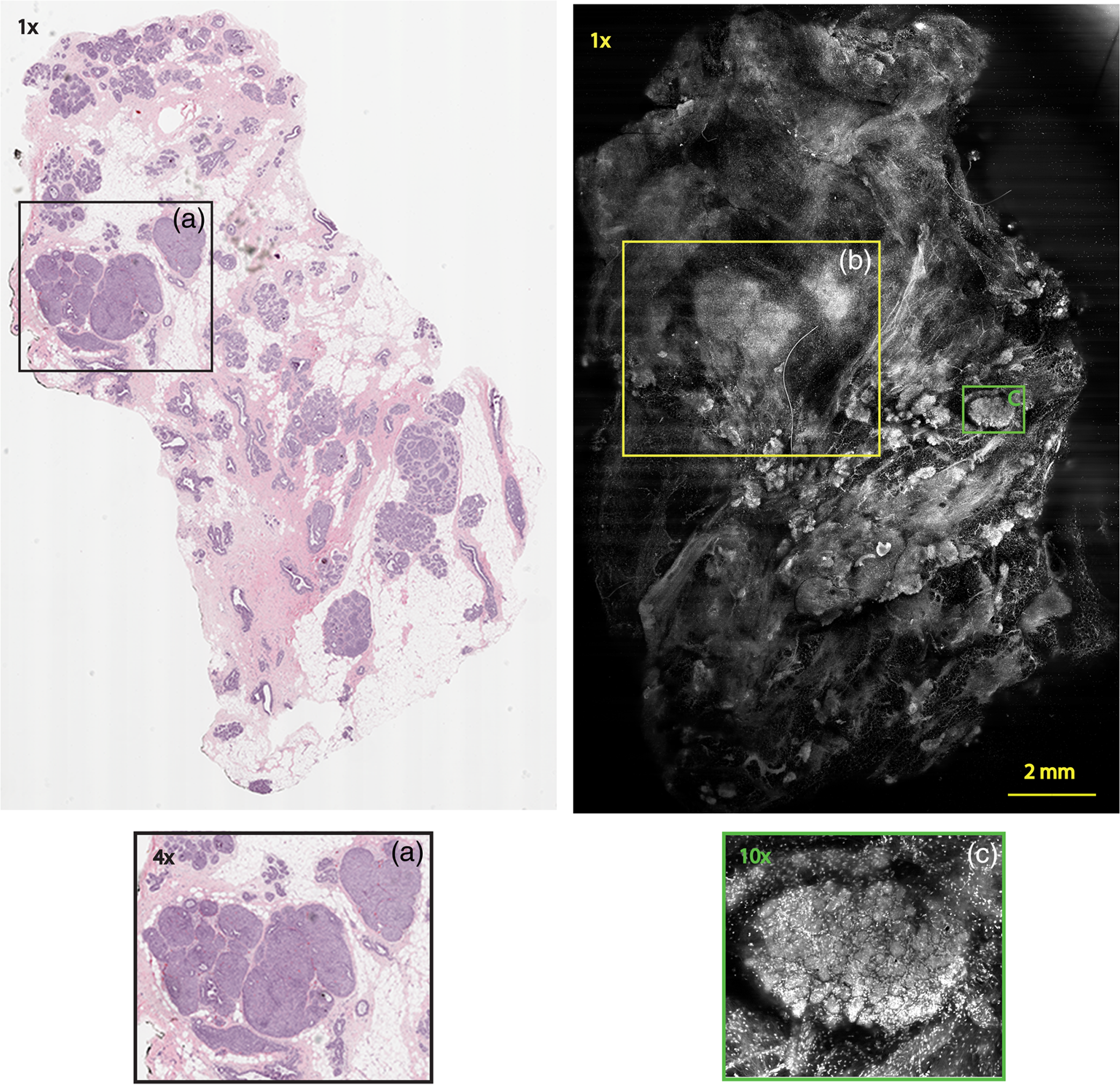 4.DiscussionSeveral studies show that confocal imaging can be useful for detecting tumor morphology in fresh breast tissue. However, because of selective examination of relatively small areas compared to the larger sizes of tissue specimens, the potential for implementation into routine clinical workflow was not directly assessed. We studied the feasibility of using CSM to quickly scan large pieces of fresh breast tissue and accurately interpret the images by employing two strategies that directly simulate workflow and address the needs of the pathologist.
Under these conditions, the discernment of invasive neoplastic and nonneoplastic features is possible to identify with CSM mosaics of fresh human breast tissue. We found very good concordance between CSM mosaics and the corresponding histopathology. Most invasive mammary carcinomas were correctly identified and the shape and invasive front of the tumor were easily distinguished. Not surprisingly, at this early stage of CSM imaging, we found some limitations and the need for further development. While the mosaics of 30 specimens showed concordance, four were discordant. The four cases that were misdiagnosed on the CSM images can be attributed to both technical difficulties when imaging the tissue with the CSM microscope and mismatch between the imaged plane (optical section) and the physical H&E-stained section. For example, in the case shown in Fig. 8, we suspect the following that the plane of tissue in the CSM image and final H&E-stained section from the corresponding FFPE tissue is different. During the routine processing to prepare the H&E-stained slide, the FFPE tissue block is trimmed to obtain a full-faced section of the tissue for H&E staining. This process of trimming the tissue may produce an H&E-stained section that shows a tissue plane deeper than the imaged surface, which may account for discordance. Another possibility for the discordance is that the mucinous carcinoma did not produce a desmoplastic stromal reaction (H&E-stained section, Fig. 8), and the absence of stromal desmoplasia may have made it difficult to distinguish the focus of mucinous carcinoma from the normal lobular breast parenchyma on the CSM mosaic, which was called benign. To this end, we are exploring techniques and methods to improve correlation between histopathology and CSM images. We suspect a technical difficulty with the leveling mechanism. Our leveling mechanism (see Sec. 2) yielded good results in majority of the specimens. For example, in the case of Fig. 9, we believe that on one-half of the mosaic the imaging was deeper into the tissue (where the image is blurred) and shallower in the other half where there is clear showing of small benign lobules and stroma. The leveling scheme is an iterative process that is currently performed manually. The process is labor intensive and time-consuming. Therefore, the leveling procedure is performed only at the beginning of the day when other types of tissue specimens, such as skin and head-and-neck, are sometimes imaged prior to breast specimens. It is possible for the flattened sample surface and the focal plane to fall out of alignment during the change to other types of specimens. We are currently developing an automated method to perform leveling prior to scanning of each specimen. As for technical difficulty with the tissue holder, we discovered that in three cases it failed to apply pressure on the tissue properly. In one case, the pressure was sufficient to flatten and level the more pliable benign breast tissue producing a clear image, but the same applied pressure was not enough to level the center of stiffer and less compliant invasive carcinoma (Fig. 10), which led to dark empty areas in the CSM mosaic that were clearly invasive carcinoma in the H&E-stained sections. In Fig. 11, the pressure applied to the soft adipose tissue produced a clear image, but the firmer and relatively less compliant sclerotic stroma around the DCIS was not pressed completely on the glass causing that area of the image to be blurry [Fig. 11(d)]. Fig. 11Discordant case: top-left and top-right are the views of H&E-stained section and CSM image, respectively. DCIS present as round open ducts with papillary architecture surrounded by a prominent area of sclerosis (a) is blurred in the CSM image (c). Images (b, blue box) and (d, green box) are the zoomed-in area of interface between stromal and adipose tissue. The stromal tissue seen clearly in the H&E-stained section (b) is blurry in the CSM image (d). However, adipose tissue is imaged well in both cases.  As with any technique, to perform the necessary studies and progress toward implementation to evaluate fresh tissue during intraoperative evaluation, a key requirement for pathologists will be to learn to consistently and accurately read and interpret CSM microscopy mosaics, in a manner equivalent to the examination of traditional H&E-stained slides. An advantage of this CSM technique is the large FOV allowing the pathologist a complete view of the entire tissue and the ability to quickly zoom in on areas of interest. A system that mimics the way a pathologist reads H&E-stained slides will likely make it easier to become proficient at reading CSM images and gain acceptance. Furthermore, to improve the learning curve and gain further acceptance, another approach is for the appearance of mosaics to be in colors and contrast that will be familiar. The CSM microscope will be able to acquire images with two contrast mechanisms, fluorescence and reflectance, simultaneously. This allows us to use a nuclear contrast agent to highlight the nuclei in a fluorescence image while acquiring a reflectance image of the cellular and dermal collagen structures of the specimen. The process simulates the staining mechanism of H&E histopathology where hematoxylin provides the nuclear contrast and eosin highlights the cytoplasm, connective tissue, and extracellular substances. The fluorescence image and the reflectance image will be combined and digitally colorized with purple and pink spectrum such that the appearance of the CSM mosaics emulates traditional H&E-stained histopathology. Therefore, we use the term digital-H&E (dH&E) to describe this process. Unlike many pseudocoloring techniques, which are “artificial” (i.e., purely digital, without a physical basis), our digital-H&E technique is based on biological and physical (optical) characteristics of the tissue and the staining process to draw contrast, similar to traditional H&E staining. Although a similar approach that was reported in our earlier work in imaging skin,26 we expect produce sharper images with the CSM microscope by correcting for chromatic shift between reflectance and fluorescence images. The integration of the mosaicking and dH&E approaches is in progress. An example dH&E image is shown in Fig. 12. Breast lobular units are visible as a cluster of glands and ducts were visible as round structures within the fibrous stroma. Histopathology shows large lobules, with peripheral nuclei, corresponding to the ones observed on the CSM mosaic. Breast ducts as seen on fluorescence confocal microscopy appear as snake-like fluorescent tubular structures with two rows of cells. Fig. 12Digitally stained (dH&E) confocal mosaic. Grayscale images of breast tissue specimen were acquired in two contrast modes—reflectance and fluorescence. The fluorescence image highlights nuclei similar to hematoxylin stain, and reflectance image highlights stroma similar to eosin stain in H&E. The grayscale images, fluorescence and reflectance, are overlaid and mapped to blue and pink color scales respectively (a). Magnified view of a terminal ductal lobular unit (TDLU) from CSM image a. (b) Nuclei that were originally imaged in fluorescence grayscale (black/white) contrast appear blue, while stroma that was originally in reflectance grayscale contrast appears pink, similar to that seen with H&E staining in pathology. (c) The same TDLU in the histology H&E-stained section.  In this report, we described our experience with examining fresh breast tissue with a CSM microscope, which images an area of (about ) of tissue with cellular-level resolution. The strengths of CSM imaging, which distinguishes it from conventional histopathology, are as follows:
Finally, there is clear benefit for knowing if a breast margin is positive during surgery since re-excision can be immediately performed; avoiding the morbidity and cost of a second operation. However, at our institution, we do not perform intraoperative assessment of breast tissue margins because current intraoperative techniques are inadequate for complete margin assessment. The ability to scan large areas of fresh tissue potentially allows this technology to be used as an alternative for intraoperative assessment of tissue whether it is margin assessment or conservation of small tissue specimens, or selection of the most significant tissue for frozen section. In addition, the use of CSM technique could be extended to: (1) evaluating intraprocedural adequacy of core-needle biopsy procedures; (2) documenting histology of biobanked tissues; (3) guiding tissue selection for molecular studies; (4) targeting areas of interest in fresh tissue during the grossing of specimens so that the number samples to be processed for histology is decreased. 5.SummaryCSM microscopy is among several emerging methods that is nondestructive and that allows imaging of large, freshly excised tissue specimens with cellular-level resolution. CSM images may be useful for quick assessment of fresh tissue, and as an adjunct to conventional histopathology. Our study on 34 specimens highlights the potential utility of CSM microscopy. These preliminary results are encouraging; CSM microscopy has the potential to provide rapid evaluation of breast parenchyma. We have presented the current technical difficulties in imaging breast tissue. Since there appear to be no fundamental barriers, the technical difficulties can likely be overcome with better engineering of the device. In addition to an improved device, further studies and trials will be required to determine if CSM mosaics can be used by the pathologist in actual intraoperative settings to consistently and accurately identify changes in neoplastic development, assess interobserver reproducibility and diagnostic accuracy between CSM and traditional histopathology. AcknowledgmentsWe thank the surgeons and support staff of MSKCC Department of Surgery—Breast Service and staff of Tumor Procurement Service of Pathology Core Facility. We also thank Jessica Dobbs and Rebecca Richards-Kortum of Rice University, and Christi Alessi-Fox at Caliber Imaging and Diagnostics (formerly, Lucid, Inc.) for discussions in breast tissue imaging. Funding support was provided, in parts, by the National Institute of Health Grants Nos. R01EB012466 and R01EB020029 from the National Institute for Biomedical Imaging and Bioengineering and R01CA156773 and R01CA201399 from the National Cancer Institute, by the MSKCC’s Cancer Center support Grant No. P30CA008748, and by the MSKCC 3-DF technology development fund. This study was approved by the Institutional Review Board of MSKCC. ReferencesY. Ardeshirpour et al.,
“In vivo fluorescence lifetime imaging monitors binding of specific probes to cancer biomarkers,”
PLoS One, 7
(2), e31881
(2012). http://dx.doi.org/10.1371/journal.pone.0031881 POLNCL 1932-6203 Google Scholar
O. Assayag et al.,
“Large field, high resolution full-field optical coherence tomography: a pre-clinical study of human breast tissue and cancer assessment,”
Technol. Cancer Res. Treat., 13
(5), 455
–468
(2014). http://dx.doi.org/10.7785/tcrtexpress.2013.600254 Google Scholar
M. R. Austwick et al.,
“Scanning elastic scattering spectroscopy detects metastatic breast cancer in sentinel lymph nodes,”
J. Biomed. Opt., 15
(4), 047001
(2010). http://dx.doi.org/10.1117/1.3463005 Google Scholar
I. J. Bigio et al.,
“Diagnosis of breast cancer using elastic-scattering spectroscopy: preliminary clinical results,”
J. Biomed. Opt., 5
(2), 221
–228
(2000). http://dx.doi.org/10.1117/1.429990 Google Scholar
S. A. Boppart et al.,
“Optical coherence tomography: feasibility for basic research and image-guided surgery of breast cancer,”
Breast Cancer Res. Treat., 84
(2), 85
–97
(2004). http://dx.doi.org/10.1023/B:BREA.0000018401.13609.54 Google Scholar
J. Q. Brown et al.,
“Optical spectral surveillance of breast tissue landscapes for detection of residual disease in breast tumor margins,”
PLoS One, 8
(7), e69906
(2013). http://dx.doi.org/10.1371/journal.pone.0069906 Google Scholar
J. L. Dobbs et al.,
“Feasibility of confocal fluorescence microscopy for real-time evaluation of neoplasia in fresh human breast tissue,”
J. Biomed. Opt., 18
(10), 106016
(2013). http://dx.doi.org/10.1117/1.JBO.18.10.106016 Google Scholar
K. S. Johnson et al.,
“Elastic scattering spectroscopy for intraoperative determination of sentinel lymph node status in the breast,”
J. Biomed. Opt., 9
(6), 1122
–1128
(2004). http://dx.doi.org/10.1117/1.1802191 Google Scholar
M. D. Keller et al.,
“Development of a spatially offset Raman spectroscopy probe for breast tumor surgical margin evaluation,”
J. Biomed. Opt., 16
(7), 077006
(2011). http://dx.doi.org/10.1117/1.3600708 Google Scholar
M. D. Keller et al.,
“Autofluorescence and diffuse reflectance spectroscopy and spectral imaging for breast surgical margin analysis,”
Lasers Surg. Med., 42
(1), 15
–23
(2010). http://dx.doi.org/10.1002/lsm.v42:1 Google Scholar
A. M. Laughney et al.,
“System analysis of spatial frequency domain imaging for quantitative mapping of surgically resected breast tissues,”
J. Biomed. Opt., 18
(3), 036012
(2013). http://dx.doi.org/10.1117/1.JBO.18.3.036012 Google Scholar
M. T. Tilli et al.,
“Real-time imaging and characterization of human breast tissue by reflectance confocal microscopy,”
J. Biomed. Opt., 12
(5), 051901
(2007). http://dx.doi.org/10.1117/1.2799187 Google Scholar
R. Patel et al.,
“Polarization-sensitive multimodal imaging for detecting breast cancer,”
Cancer Res., 74
(17), 4685
–4693
(2014). http://dx.doi.org/10.1158/0008-5472.CAN-13-2411 Google Scholar
R. Patel et al.,
“Delineating breast ductal carcinoma using combined dye-enhanced wide-field polarization imaging and optical coherence tomography,”
J. Biophotonics, 6
(9), 679
–686
(2013). http://dx.doi.org/10.1002/jbio.v6.9 Google Scholar
Y. Xia et al.,
“YAP promotes ovarian cancer cell tumorigenesis and is indicative of a poor prognosis for ovarian cancer patients,”
PLoS One, 9
(3), e91770
(2014). http://dx.doi.org/10.1371/journal.pone.0091770 POLNCL 1932-6203 Google Scholar
L. G. Wilke et al.,
“Rapid noninvasive optical imaging of tissue composition in breast tumor margins,”
Am. J. Surg., 198
(4), 566
–574
(2009). http://dx.doi.org/10.1016/j.amjsurg.2009.06.018 Google Scholar
K. M. Kennedy et al.,
“Quantitative micro-elastography: imaging of tissue elasticity using compression optical coherence elastography,”
Sci. Rep., 5 15538
(2015). http://dx.doi.org/10.1038/srep15538 Google Scholar
Y. Wang et al.,
“Quantitative molecular phenotyping with topically applied SERS nanoparticles for intraoperative guidance of breast cancer lumpectomy,”
Sci. Rep., 6 21242
(2016). http://dx.doi.org/10.1038/srep21242 Google Scholar
R. Patel et al.,
“Multimodal optical imaging for detecting breast cancer,”
J. Biomed. Opt., 17
(6), 066008
(2012). http://dx.doi.org/10.1117/1.JBO.17.6.066008 Google Scholar
A. Bennassar et al.,
“Rapid diagnosis of two facial papules using ex vivo fluorescence confocal microscopy: toward a rapid bedside pathology,”
Dermatol. Surg., 38
(9), 1548
–1551
(2012). http://dx.doi.org/10.1111/j.1524-4725.2012.02467.x Google Scholar
M. Ragazzi et al.,
“Fluorescence confocal microscopy for pathologists,”
Mod. Pathol., 27
(3), 460
–471
(2014). http://dx.doi.org/10.1038/modpathol.2013 Google Scholar
A. Bennassar et al.,
“Fast evaluation of 69 basal cell carcinomas with ex vivo fluorescence confocal microscopy: criteria description, histopathological correlation, and interobserver agreement,”
JAMA Dermatol., 149
(7), 839
–847
(2013). http://dx.doi.org/10.1001/jamadermatol.2013.459 Google Scholar
C. Longo et al.,
“Inserting ex vivo fluorescence confocal microscopy perioperatively in Mohs micrographic surgery expedites bedside assessment of excision margins in recurrent basal cell carcinoma,”
Dermatology, 227
(1), 89
–92
(2013). http://dx.doi.org/10.1159/000353577 DERMEI 0742-3217 Google Scholar
S. Abeytunge et al.,
“Confocal microscopy with strip mosaicing for rapid imaging over large areas of excised tissue,”
J. Biomed. Opt., 18
(6), 061227
(2013). http://dx.doi.org/10.1117/1.JBO.18.6.061227 Google Scholar
S. Abeytunge et al.,
“Rapid confocal imaging of large areas of excised tissue with strip mosaicing,”
J. Biomed. Opt., 16
(5), 050504
(2011). http://dx.doi.org/10.1117/1.3582335 JBOPFO 1083-3668 Google Scholar
D. S. Gareau,
“Feasibility of digitally stained multimodal confocal mosaics to simulate histopathology,”
J. Biomed. Opt., 14
(3), 034050
(2009). http://dx.doi.org/10.1117/1.3149853 Google Scholar
|