|
|
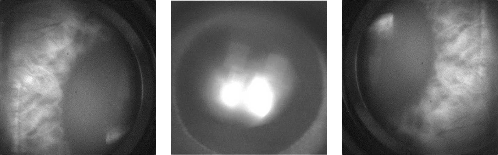
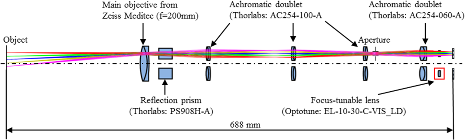
1.IntroductionDuring the operation using a conventional surgical microscope, the surgeon has to remain in the same position for a long period of time, which causes musculoskeletal pain.1 Common cause of pain is the strain placed on the head, neck, and arms during the operation. Some procedures, such as in craniotomy, require long working times with outstretched arms and remaining in a standing position without breaks. Furthermore, every 25 mm the head moves forward, the head, neck, and upper back muscles must compensate to support an additional 4.5 kg of weight.2 This can result in aches and pains, which could cause severe headaches and chronic pains. It is our goal to provide the surgeon with a digital surgical microscope, which offers all the functionality the surgeon experiences with a conventional microscope, albeit offering the freedom of free head movement via displaying the image on a screen or digital stereoscopic displays. Various attempts have already been made to ease the working condition of the surgeon via the introduction of a “digital recording stereo microscope” in combination with a digital displaying stereo microscope, which can freely be moved in the room and adjusted to any position, such as Ergo View (developed by ARRI GmbH & Co KG3). On the other hand, the information can likewise be displayed on a screen, such as the Zeiss surgical microscope OPMI Pentero 9004 in combination with the three-dimensional (3-D) visualization platform Trenion 3-D HD or the ARRI GmbH & Co KG developed Arriscope.5 However, the functionality of the eye and the head motion has not been taken into account during the development of these devices to enable refocusing and changing viewing angle, when shifting the pupil, as proposed in our digital surgical microscope. The digital surgical microscope is composed of two units: first, a recording unit represented by a digital recording stereo microscope, which offers accommodation and pupil shift that are enabled via the application of an adaptive optomechanical system; second, a displaying unit, which represents the human interface device. The displaying unit can be implemented via a digital displaying stereo microscope or a 3-D monitor, as schematically shown in Fig. 1. Head and eye tracking are applied to the displaying unit to obtain a signal for shifting the pupil in the recording unit. The signal relevant for the accommodation adjustment can be obtained from a refractometer6 or via eye tracking combined with scanning the topography and refocusing on the region of interest. Fig. 1Flowchart of recording and displaying devices with regards to the information recorded and transferred 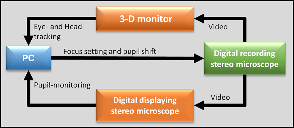 In that manner, an automated functionality of the digital recording stereo microscope is possible. To compensate for the eye’s accommodation capability, different systems have so far been proposed in combination with digital imaging. Commonly zoom lenses are applied,7 which are based on the longitudinal displacement of one or more lens pairs via a motorized stage. However, this approach requires more space and hence does not enable a compact setup. The application of Alvarez–Lohmann cubically surfaced lenses8,9 enable variable focus based on lateral shifts and therefore offer a more compact setup, albeit with the trade-off that the impact of aberrations is increased. Spatial light modulators are digital devices, by which the phase can be manipulated as to enable the generation of different foci.10 However, the extent to which the focus can be changed is restricted by the number of pixels and their corresponding dynamic range (bit depth).11 Two foci accommodation is enabled via the application of birefringent lenses, albeit restricted to polarized light and hence polarization maintaining properties of the specimen. The number of refocused planes can be increased via the application of multiple birefringent lenses in combination with changing the polarization orientation as discussed.12 Over the last decades, tunable lenses have been developed and have become commercially available. The working principle of tunable lenses is usually based on a changed curvature of a flexible polymer membrane caused by the application of a well-defined point symmetric force distribution that can be tuned. They can be based on elastomer lenses,13 electro-wetting,14,15 liquid crystals,16 or an active glass-piezo composite lens.17 Tunable lenses offer the advantage of a large focal range without any moving parts within a few milliseconds only, thus allowing a compact setup and fast switching among different foci. Hence, they have been used in many optical systems, especially in microscopes, to make sure that the moving object stays in focus18,19 or to focus on different optical plans in -directions.20,21 On the other hand, mimicking of the eye’s pupil shift (e.g., due to head motion) can be realized by a laterally moving aperture on an stage or by a spatial light modulator. The latter of the two offers some temporal benefits. However, it suffers from disturbing artifacts arising from the pixelization of the device, which can result in undesired diffraction orders. Moreover, the contrast is lower than 22 and therefore the light cannot be 100% blocked. Therefore, the proposed digital recording stereomicroscope will be based on the application of tunable lenses for mimicking the eye’s accommodation and an shifted stage for mimicking the eye’s pupil movement. Before the recording unit can be set up, eye tracking needs to be implemented in the displaying unit. Head and eye tracking for 3-D monitors are already commercially available. There are several companies offering eye tracking devices23–25 and head tracking devices.26–28 Several 3-D screen technologies have been developed ranging from traditional techniques, such as color filters (blue and red) in combination with the stereoscopic information encoded by the same colors.29 Since the color is used to display the stereoscopic information, these images are, strictly speaking, monochromatic. Polarization-based displays take advantage of opposite circularly polarized light to encode the stereoscopic information that can be viewed using corresponding polarization filters.30 High-speed shutter glasses that are synchronized with the display likewise enable stereoscopic vision.31 The aforementioned techniques suffer from the discomfort that glasses are needed to display the stereoscopic information. Displays such as under development at Seereal Technologies mitigate this problem using microlens arrays in combination with switchable background light sources of the display to direct light to the left and right eyes.32 This technology requires eye tracking, and the number of viewers is limited due to the reduced resolution. Another technique developed by Seereal is based on holography, which can be viewed with the naked eye.33 2.Pupil Monitoring Through a Digital Displaying Stereomicroscope2.1.Optomechanical DesignIn the following, the development of an illumination and imaging device that can be used for eye tracking and pupil monitoring will be discussed. The digital displaying stereo microscope used is a prototype that has been developed by Carl Zeiss Meditec. The system to develop should easily be attached to the existing digital displaying stereomicroscope. At first, the digital displaying stereo microscope was characterized to determine important optical parameters. The parameters are as follows: magnification of 0.97, field of view of and numerical aperture of the eyepiece of . With these parameters at hand, the illumination and imaging system have been optomechanically designed, as shown in Fig. 2 for the mechanical design and Fig. 3 for the optical design. The practically implemented optomechanical setup can be seen in Fig. 4 and the optical parameters of the lenses employed are listed in Table 1. The limited field of view accessible by the digital stereomicroscope of imposes some restrictions on the maximum amount of pupil movement. In fact, in addition to the lateral pupil movement, the surgeon has to turn his head to access the outmost positions of the display. The initial illumination design was based on infrared light-emitting diode illumination, emitting at a wavelength at which the visual perception is not disturbed (830 nm). However, internal reflection effects of the digital displaying stereo microscope, which is optimized for visible light applications, resulted in strongly disturbed images (bright background due to reflections), which made the application of near-infrared illumination and imaging impossible. Therefore, the entire design of the illumination system had to be changed. A good solution was found by simultaneously using the stereo displays as a light source. In that manner, the issue with disturbing reflections effects could be minimized without any disturbing artifacts arising for the visual perception of the surgeon. A beam splitter plate was implemented in the digital displaying stereo microscope at a position where the light beams are collimated. This location was originally occupied by a reflection prism, which had been removed and replaced. In that manner, it was possible to direct the reflected light from the eye to the camera. Furthermore, during the design, it was taken care that the high NA provided by the eyepiece of the digital stereomicroscope could be adjusted via an iris diaphragm to monitor the pupil without being too restrictive on the positioning stability of the surgeon’s eye. It was later realized that due to the reduced irradiance caused by a smaller diameter of the iris diaphragm, the integration time had to be increased, resulting in motion blur due to the eye’s movement within the integration time. Therefore, in combination with a chin-forehead rest, to ease stable positioning of the surgeon, the diameter of the diaphragm was set to a value of resulting in an object sided NA of 0.033, which still enables a sufficiently large irradiance on the sensor so that motion blur does not yet occur. Moreover, binning was applied to the CCD sensor (Vistek eco415MVGE, SNR 50 dB) to increase the integration area34 and hence keep the integration time within the required temporal constrain of 50 ms (temporal frequency should be faster than the latency of the human eye, which is 20Hz). The images obtained from the eye through the digital displaying stereomicroscope with changing pupil position are shown in Fig. 5. In Ref. 35, the image postprocessing routines applied to obtain the pupil positions for these images are described. Fig. 4Practically implemented setup of the illumination and imaging system for pupil monitoring: (a) scaffolding of construction and (b) system attached to the existing digital displaying Zeiss stereomicroscope.  Motivated by the tight constrains, temporal and optical, of the current pupil imaging system, an additional solution has been developed, which is based on endoscopic monitoring in the eyepiece. In that manner, the limitations imposed on recoverable field of view, the irradiance, and the positioning stability could all be relaxed. Another possibility to track the pupil in surgical microscopy has been discussed in Ref. 36. It is based on an optical system that needs to be attached to the eyepiece and therefore relies on long eyepiece to eye distance to accommodate such an optical pupil tracking device, which has the drawback that the field of view that can be accessed by the surgeon’s eye is smaller than in the conventional stereomicroscopy. Hence, in addition to the current state of the art, two systems have been developed for imaging the pupil. The first is based on an additional monitoring system, as described above, which involves imaging through the existing digital displaying stereomicroscope, and a second system that is based on endoscopic imaging close to the surgeon’s eye without any interaction with the digital stereomicroscope’s optical elements (see Fig. 6). Fig. 6(a) Endoscopic setup for pupil monitoring, (b) holes in the eyepiece for the endoscope fiber, and (c) with smartphone and endoscope recorded image of a human eye.  The latter is more favorable since it is not constrained by the optical system of the stereomicroscope, which has been optimized to image the picture provided by the digital displays with sufficiently high resolution on the surgeon’s retina. Once the pupil has been detected and its position has been determined, the necessary information has been obtained to calculate the viewing direction, which can be used as input parameters for the digital recording stereomicroscope as to change the pupil position or to adjust the focus. The focus setting can be obtained from the point at which the viewing directions of both eyes intersect and from a priori knowledge about the surface topography of the investigated region. 3.Digital Recording Stereomicroscope3.1.Optomechanical DesignIn this section, a description of the digital recording stereo microscope is presented, which allows for accommodation and pupil shift. The temporal requirement on the system was to deliver a temporal resolution better than 50 ms (20 Hz) in accordance with the human eye’s latency.37 Furthermore, the optical requirements on the system were a spatial resolution of and a field of view of , which are common specifications among surgical microscopes. The optical design is shown in Fig. 7, and the mechanical design in Fig. 8(a). The practically implemented imaging system is shown in Fig. 8(b) Important optical parameters are listed in Table 2. Special attention was given to the optical design of the recording system to match the imaging parameters and quality of a conventional stereo microscope (Zeiss OPMI Pico). Fig. 8Recording system: (a) mechanical design, (b) experimentally implemented prototype system, and (c) simulation result for input object of 27-mm diameter in ZEMAX. 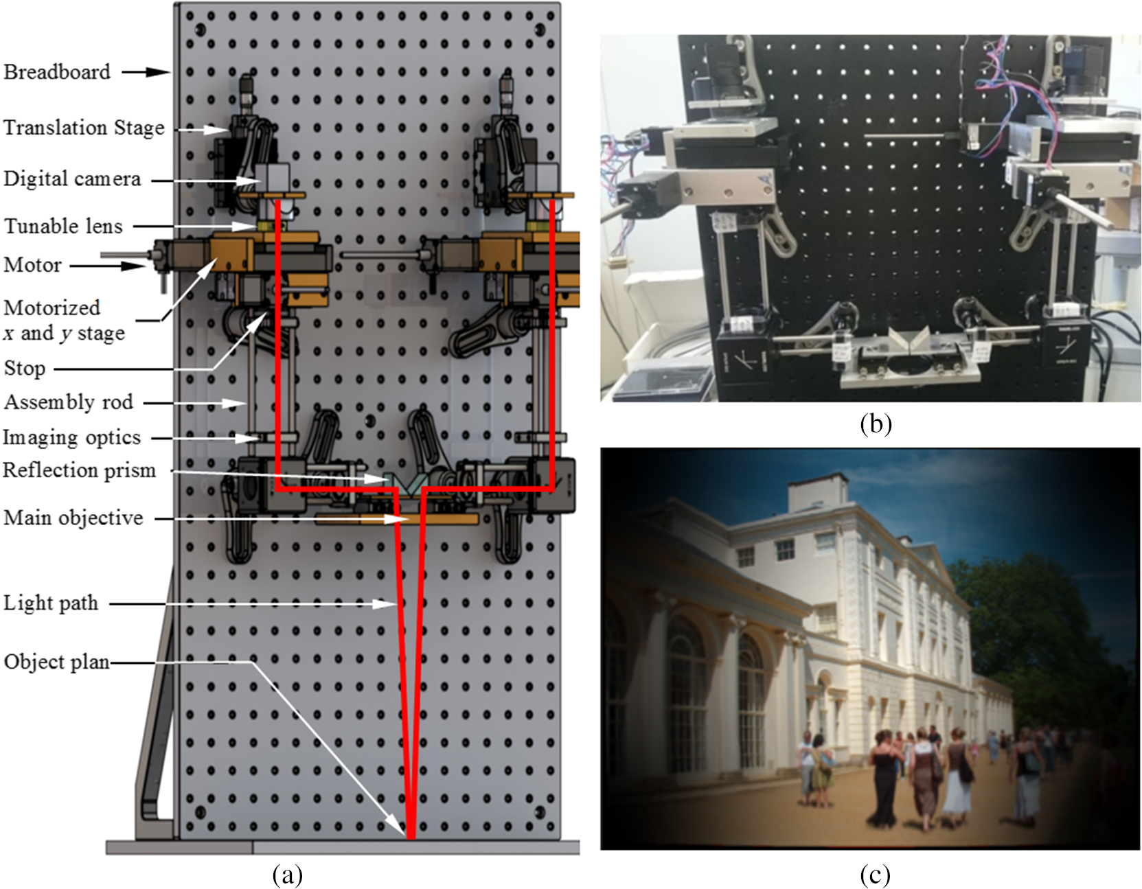 The imaging performance of the recording system is shown in Fig. 8(c), which illustrates the image quality obtained from an example input picture of 27-mm diameter. In Fig. 9(b), the modulation transfer function (MTF) and Seidel aberration coefficients are displayed, which demonstrate a good imaging performance of the adaptive digital stereo microscope near the optical axis. Toward the edge, a reduction of the performance of the optical system is apparent. This is due to an increase of aberrations with increasing distance to the optical axis, as shown in Fig. 9(b), and vignetting, which causes a loss of brightness toward the edge of the simulated image. Fig. 9Imaging performance of recording system displayed in Fig. 7: (a) MTF curve with -axis representing the spatial frequency in lp/mm and -axis representing the contrast and (b) field-dependent Seidel coefficients. 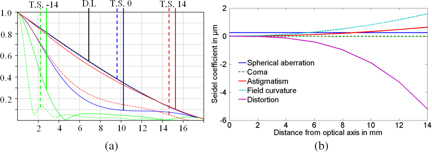 The optical performance parameters obtained for the digital adaptive system in comparison to a conventional (Zeiss OPMI pico) stereo microscope are shown in Table 3. The refocusing range of the conventional stereo microscope (see Table 3) is based on the effect of the average human eye accommodation range from infinity (relaxed eye) to 250 mm (accommodated eye). Table 1Lens data of lenses shown in Fig. 3.
ARC, antireflex coating. Table 2Lens data of achromatic lenses shown in Fig. 7.
ARC, antireflex coating. Table 3Comparison of optical parameters conventional and digital stereo microscope.
In the digital recording stereo microscope (see Figs. 7 and 8), accommodation is implemented via the addition of two tunable lenses (EL-10-30-C-VIS-LD) from the company Optotune AG,13 one for each arm of the stereoscopic system. The Optotune lens enables the application of a variable focal length ranging from 80 to 200 mm. The root-mean-square wavefront error at 525 nm and 0 mA is smaller than 0.15 in horizontal orientation and 0.25 in vertical orientation (121.25 nm). The difference between the two orientations is mainly caused by gravity-induced coma,38 as demonstrated in Fig. 10, which represents the wavefront error with respect to the orientation and focus setting applied for 525 nm. The Optotune lens can be set to a new position within 15 ms, which is within the temporal requirements imposed on our system (faster than 20 Hz). Fig. 10Root-mean-square wave aberration error with respect to the focal length applied to the Optotune lens EL-10-30-VIS-LD, which have kindly been provided by Optotune Switzerland AG.  With this Optotune lens in place, the refocusing range of our system becomes 55 mm. To implement active displacement of the pupil position, two different possibilities have been considered: At first, a two axis tilt mirror positioned in the intermediate image plane has been taken into account. The second possibility is based on positioning a diaphragm in an intermediate pupil plane, serving as an aperture stop for the entire system, and in that manner modeling the function of the eye’s pupil. This diaphragm will be translated via a motorized stage in order to simulate the change of the eye’s pupil position. The latter of the two has been implemented due to the following reasons:
Based on the latency of the human eyes with regards to changing pupil position, the temporal requirement imposed is 50 ms (20 Hz).37 Therefore, a conventional manual, stage, was modified by the attachment of two linear actuators [see Fig. 11(a)] from the company Nanotec Electronic GmbH & Co. KG (L2818L0604-T5X5), which enable a maximum speed of .39 To cover the same amount of shift at the entrance pupil in our digital recording stereo microscope in comparison to the conventional system, the diaphragm has to be displaced by . However, the total amount of shift that can be applied without significant loss caused by vignetting is . Fig. 11(a) Motorized stage for incorporating the translation of the monitored human eye’s position and (b) two prisms have a bigger free diameter than two lenses. 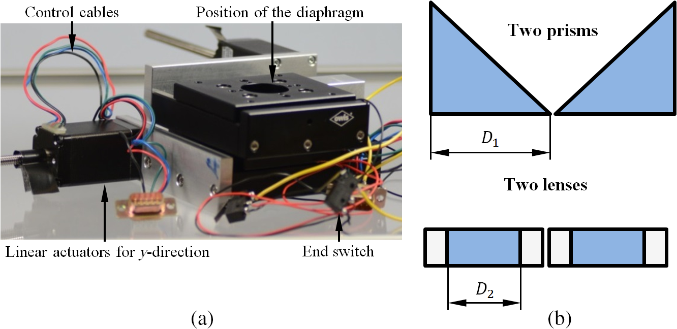 Despite the requirement to match the optical parameters as previously discussed, special attention was also given to the design of the mechanical devices, in particular to host the motorized stage, which covers 53-mm axial dimension in which no optical components can be mounted. Furthermore, care was taken during the optomechanical design to:
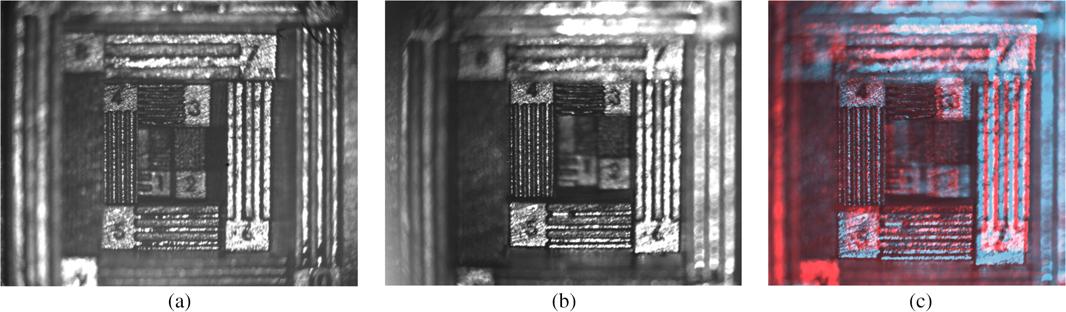
3.2.Optical ResolutionThe camera employed (XIMEA MQ013MG-E2) has a pixel pitch of . To ensure sufficient sampling of the high-resolution elements, the pixel pitch was multiplied by a factor of 2.5 so that a period [black and transparent strip of United States Air Force (USAF) test target] can unambiguously be displayed. For instance, a factor of 2, as suggested by Nyquist criteria, could result in a homogenous gray level over the entire test-target element of interest, in case the image of the black strip falls between two pixels. Consequently, it would be impossible to image such a test-target group. The magnification of the system shown in Fig. 7 is . Hence, our system can deliver a resolution of To confirm this theoretically calculated resolution, a USAF test target has been employed. Rather than taking into account only a single cross section for a considered test-target element, the optical resolution was determined by averaging all cross sections across the test-target element under investigation. This approach enables a more accurate determination of the optical resolution. The averaged cross sections are shown in Fig. 12. Care was taken so that the three local minima (black strips) are visible and the ratio of the largest local minima (green dot Fig. 12) to the smallest local maxima (red dot in Fig. 12) is less than 0.73 according to Rayleigh’s resolution criterion for a circular aperture.42 A maximum spatial frequency of 17.96 line pairs/mm (group 4, element 2) could be achieved (see Fig. 12), which corresponds to a lateral resolution of . This matches well the predicted value calculated in Eq. (1). 3.3.Depth from FocusStudies on the magnification ratio and the focal length of the Optotune lens both with respect to the distance between the object and the main objective of the optical system are displayed in Figs. 13(a) and 13(b). Fig. 13Performance curves: (a) linear magnification by changing the working distance and (b) nonlinear Optotune’s focal length by changing the distance between the object and the main objective. 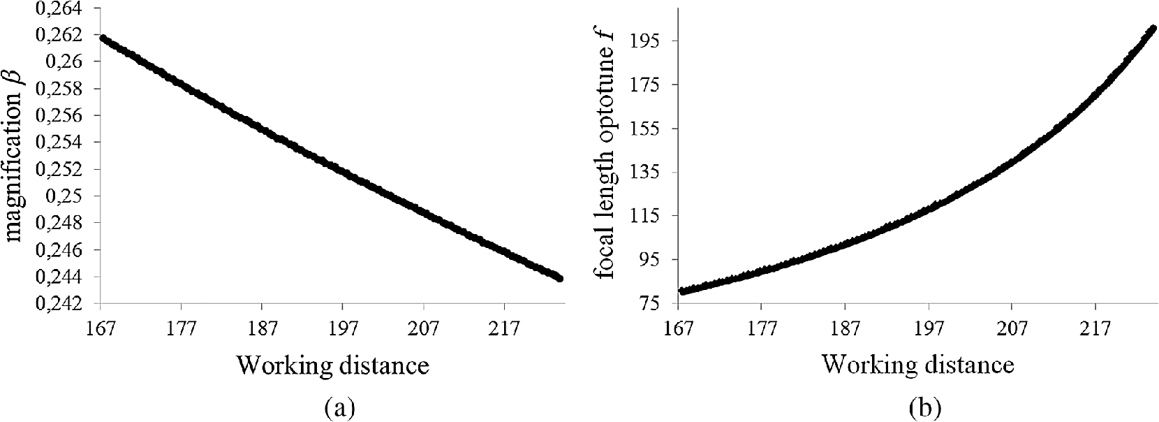 It can be seen that the magnification follows a linear trend. The average magnification is 0.252, and the max/min are . The focal length of the optune lens on the other side can best be described by an exponential curve. The information provided by the latter of the two curves has been used to construct a cuboid with the dimensions (). This cuboid was used to demonstrate the recovery of depth information as acquired by the eye in the process of accommodation (Fig. 14). The cuboid has been printed in house via the application of a 3-D printer from the company Formlabs, see Fig. 14(a). Twelve different steps have been printed, with 5-mm height difference between each step. The printing accuracy is determined by the selected layer thickness, which in our case is 0.05 mm for our Formlabs machine. Fig. 14Cuboid, (a) SolidWorks design with different line pairs/mm (min 0.5 and max ) in -direction, (b) obtained images from different planes of cuboid when applying different foci to the Optotune lens (distance between object and main objective is displayed on top of each image, whereas the corresponding focal length is shown in brackets); the refocusing capability can be appreciated watching the video (Video 1, MOV, 657 kB [URL: http://dx.doi.org/10.1117/1.JBO.22.5.056007.1]), where all still images shown in (b) are present, (c) topography map obtained using sliding window approach with white scale bar representing 4.5 mm. 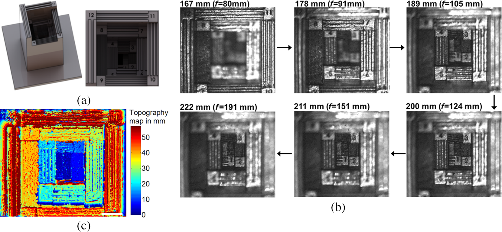 Applying different voltage settings to the Optotune lens enables the recovery of different axial planes for the digital recording stereo microscope. The results obtained are shown in Fig. 14(b). We start changing the distance by and end at . Images at different refocusing distances are shown in Fig. 14(b). From these images, it is possible to obtain a 3-D image while the magnification also has to be taken into account. The generation of the topograpy map shown in Fig. 14(c) is based on the calculation of the variance within a sliding window that is moved across each of the images, as discussed in Ref. 43. A structured object, which is in focus, results in a high variance value. Comparing the different variance values in a pixelwise manner for all the processed images and picking out the largest enables the recovery of the in-focus plane for the pixel under consideration. In that manner, all the pixels are processed. We have been using a window size of to obtain the topography map. The topography map obtained can be used to actively steer the optotune lens in combination with pupil tracking, so that the object region the surgeons looks at automatically becomes refocused. 3.4.Depth Information by Stereoscopic VisionThe field of view at which stereoscopic vision is enabled depends on the working distance applied and can slightly be changed when shifting the pupil. This is in analogy to the human eye, where the pupil is shifted toward the nose for near-sided objects and in central position for far sided objects. From Fig. 15, it can be seen that the largest stereoscopic field of view can be recovered at a working distance of 170 mm when the pupil is as at central and inside shifted position and amounts to . The latter of the two dimensions remains the same for all pupil positions, since the stereoscopic vision is predominately determined by the horizontal pupil position (first dimension). At 200-mm working distance and central pupil position, the overall largest stereoscopic field of view can be obtained covering . At 220-mm working distance, the largest field of view () can be recovered when the pupil is displaced by 3-mm away from the optical axis of the main objective. Hence, changing the focal length applied to the Optotune lens ought to be accompanied with a change of the pupil position in order to enable recovering a large stereoscopic field of view, see Fig. 15(a). Another important parameter for stereoscopic vision is the stereo angle, which determines the stereoscopic depth discrimination. According to Ref. 41, the smallest stereo angle that can still be resolved by the human eye is 10′′ under appropriate lighting conditions (at least ). The corresponding depth discrimination is a function of the stereobasis distance and the in-focus working distance where is the stereo angle, shown in Fig. 16, which can be calculated as In our case, the stereo basis ranges between 28 and 16 mm depending on the pupil position. The corresponding stereo angles are shown in Fig. 15(b). The pupil position and the entrance pupil at the main objective are conjugated to one another.Fig. 15(a) Relationship between in-focus working distance and recoverable stereoscopic field of view, (b) stereo angle ( displayed by green line) with respect to the working distance and (c) corresponding stereoscopic depth discrimination ( displayed by blue line). 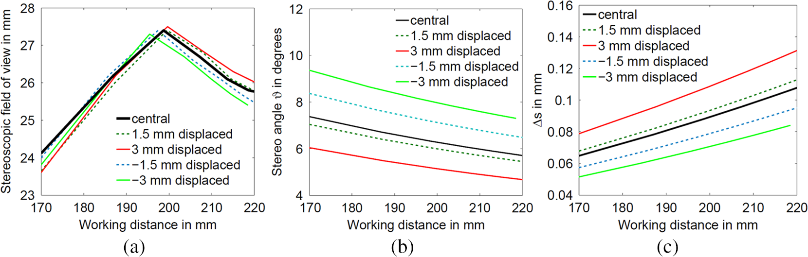 Fig. 16Schematic sketch of the stereoscopic angles at different pupil positions, indicated by different colors and corresponding depth .  Therefore, a pupil shift in the direction of the main objective’s optical axis results in an entrance pupil shift in the opposite direction, away from the optical axis, resulting in an increased stereobasis and consequently in an improved depth discrimination, as shown in Fig. 15(c) and Eq. (2). The recorded images for left and right eyes and the corresponding color-encoded stereoscopic image (left eye red colored image and right eye cyan colored image) are shown in Fig. 17. The anaglyph image shown in Fig. 17(c) can be viewed using 3-D red-cyan glasses. 3.5.Perspective ImagingThe perspective, an additional depth clue of the eye, which is realized by different viewing directions, as when laterally moving the eye and/or the head, is investigated in the following. The digital recording microscope enables perspective imaging by means of moving the diaphragm in the intermediate main objective’s pupil plane by the motorized stage. As a proof of principle, a 3-D device with two bars occluding the field of view has been printed in house, as shown in Fig. 18(a). The two bars have a distance of 4.1 mm and are located at a distance of 70 mm to the in-focus object plane, which project a shadow on the in-focus object plane. Changing the location of the aperture in the intermediate pupil plane enables the recovery of object details, which have previously been hidden by the shadow. This is in analogy to the perspective imaging experience when moving the eye’s pupil often accompanied with lateral head movement. Fig. 18Perspective view: (a) device to demonstrate the possibility to apply different perspective views, (b) results obtained from different viewing direction when moving the aperture in -direction; to appreciate the perspective impression, a movie of the still images represented and further recorded images while shifting the pupil are shown in the video (Video 2, MOV, 739 kB [URL: http://dx.doi.org/10.1117/1.JBO.22.5.056007.2]). 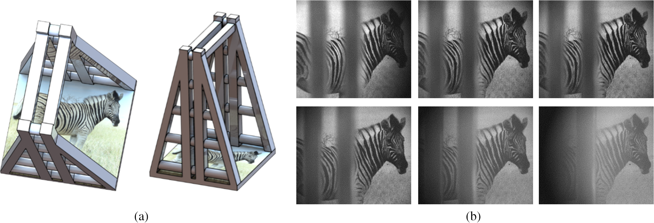 The results obtained for different aperture positions with an aperture shift of 2 mm between consecutive recordings are displayed in Fig. 18(b). The aperture shift was accompanied by refocusing procedure using the tunable lens. It could be demonstrated that different parts of the zebra are obscured, so that it is in principle possible to recover an image of the zebra, which is free of any obscuration. To test this, which is based on an algorithm similar to the one discussed in Sec. 3.3 that enables the recovery of a topography map, the sliding window, within which the variance is calculated, has a size and is moved across each of the six images. With the sliding window variance approach, it is possible to separate the shadow pattern (low to no contrast) from the object details (high contrast). In that manner, an image is generated that is predominately composed of the object details only, see Fig. 19. More sophisticated routines, such as histogram adjustment, can help to improve the final combined image. 4.Discussion and ConclusionA digital recording stereo microscope equipped with adaptable focus and pupil shift has been developed. The strict temporal constraints imposed by the latency of the human eye could be met via the introduction of a focus tunable lens to change the working distance and a high-speed stage to shift the pupil. The information for steering the system was provided from a pupil monitoring system attached to a digital displaying stereomicroscope. Two solutions for pupil monitoring have been provided, through the optical system of the digital displaying stereo microscope and endoscopic version that recorded through a hole in the eyepiece. Parameters and results describing the optical resolution, the depth clues accessible via changing the focus or the stereoscopic vision, and perspective imaging have been provided. Future work will be focused on the image processing and the many different ways of displaying the stereoscopic information (stereo display or screen). The system has been shipped to our project partners’ Zeiss Vision Lab at the University of Tübingen and will be evaluated by them using probands, such as surgeons, who will be given fine motoric tasks. AcknowledgmentsThis project has been funded by the Inter-University Center for Medical Technologies Stuttgart—Tübingen (IZST) and Carl Zeiss Meditec AG. We would like to thank Mr. Marc Gronle for his help and assistance in writing the control and acquisition software. Furthermore, we are very grateful to Mr. Ralph Knoll and Mr. Andreas Lorenz from the electrical and engineering workshops; without their contribution it would not have been possible to build the fully functional adaptive digital stereo microscope in such a timely manner. Informed consent has been obtained from all individuals included in this study. The research related to human use has complied with all the relevant national regulations, institutional policies, and in accordance to the tenets of the Helsinki Declaration, and has been approved by the authors’ institutional review board or equivalent committee. ReferencesK. Pingel,
“7 tips for better ergonomics in neurosurgery,”
(2014) http://www.leica-microsystems.com/science-lab/surgical-microscopy/7-tips-for-better-ergonomics-in-neurosurgery/ October 2016). Google Scholar
A. Kapandji, The Physiology of the Joints, 3 6th ed.Churchill Livingstone, London
(2008). Google Scholar
“Brochure-ARRISCOPE-english.pdf,”
(2017) http://www.arrimedical.com/assets/pdf/Brochure-ARRISCOPE-English.pdf March ). 2017). Google Scholar
“final_opmi_pentero_900_en_30_010_0900v.pdf,”
(2017) http://applications.zeiss.com/C1257A290053AE30/0/1F510AA365DDB9C4C1257EEC0034726D/$FILE/final_opmi_pentero_900_en_30_010_0900v.pdf February ). 2017). Google Scholar
“Broschure-ARRISCOPE-english.pdf,”
(2016) http://www.arrimedical.com/assets/pdf/Brochure-ARRISCOPE-English.pdf February 2017). Google Scholar
R. K. D. Suryakumar, S. Fernandez and W. R. Bobier,
“Dynamic photorefraction system: an offline application for the dynamic analysis of ocular focus and pupil size from photorefraction images,”
Comput. Biol. Med., 39 195
–205
(2009). http://dx.doi.org/10.1016/j.compbiomed.2008.12.006 CBMDAW 0010-4825 Google Scholar
K. Tanaka,
“Recent development of zoom lenses,”
Proc. SPIE, 3129 13
(1997). http://dx.doi.org/10.1117/12.279088 PSISDG 0277-786X Google Scholar
L. W. Alvarez,
“Development of variable-focus lenses and a new refractor,”
J. Am. Optom. Assoc., 49
(1), 24
–29
(1978). JOAPBD 0003-0244 Google Scholar
A. W. Lohmann,
“A new class of varifocal lenses,”
Appl. Opt., 9
(7), 1669
–1671
(1970). http://dx.doi.org/10.1364/AO.9.001669 APOPAI 0003-6935 Google Scholar
M. P. Lee et al.,
“Dynamic stereo microscopy for studying particle sedimentation,”
Opt. Soc. Am., 22
(4), 4671
–4677
(2014). http://dx.doi.org/10.1364/OE.22.004671 Google Scholar
A. J. Wright et al.,
“Dynamic closed-loop system for focus tracking using a spatial light modulator and a deformable membrane mirror,”
Opt. Express, 14
(1), 222
–228
(2006). http://dx.doi.org/10.1364/OPEX.14.000222 OPEXFF 1094-4087 Google Scholar
G. D. Love et al.,
“High-speed switchable lens enables the development of a volumetric stereoscopic display,”
Opt. Express, 17
(18), 15716
–15725
(2009). http://dx.doi.org/10.1364/OE.17.015716 OPEXFF 1094-4087 Google Scholar
“Focus tunable lenses,”
(2016) http://www.optotune.com/technology/focus-tunable-lenses October ). 2016). Google Scholar
“Varioptic electrowetting,”
(2016) http://www.varioptic.com/technology/electrowetting/ September ). 2016). Google Scholar
E. Simon et al., Optical Design Rules of a Camera Module with a Liquid Lens and Principle of Command for AF and OIS functions, Varioptic, France
(2010). Google Scholar
J. Draheim et al.,
“Fabrication of a fluidic membrane lens system,”
J. Micromech. Microeng., 19
(9), 095013
(2009). http://dx.doi.org/10.1088/0960-1317/19/9/095013 Google Scholar
Y. Nakai et al.,
“High-speed microscopy with an electrically tunable lens to image the dynamics of in vivo molecular complexes,”
Rev. Sci. Instrum., 86
(1), 013707
(2015). http://dx.doi.org/10.1063/1.4905330 RSINAK 0034-6748 Google Scholar
F. O. Fahrbach et al.,
“Rapid 3D light-sheet microscopy with a tunable lens,”
Opt. Soc. Am., 21
(18), 21010
–21026
(2013). http://dx.doi.org/10.1364/OE.21.021010 Google Scholar
K. Lee, E. Chung and T. Joong Eom,
“Multi-depth photoacoustic microscopy with a focus tunable lens,”
Proc. SPIE, 9323 93233O
(2015). http://dx.doi.org/10.1117/12.2076709 PSISDG 0277-786X Google Scholar
J. A. Rodrigo and T. Alieva,
“Rapid quantitative phase imaging for partially coherent light microscopy,”
Opt. Soc. Am., 22
(11), 13472
–13483
(2014). http://dx.doi.org/10.1364/OE.22.013472 Google Scholar
Y. Bitou, H. Ohta and T. Minemoto,
“High-speed and high-contrast spatial light modulator that uses electroabsorption in a GaAs single crystal,”
Appl. Opt., 37
(8), 1377
–1385
(1998). http://dx.doi.org/10.1364/AO.37.001377 Google Scholar
EyeGuide, “EyeGuide focus is the future of concussion management,”
(2017) https://eye.guide/howitworks March ). 2017). Google Scholar
A. Research,
“Eye tracking systems,”
(2017) http://www.arringtonresearch.com/ March ). 2017). Google Scholar
I. EyeTracking,
“Eyeworks, ultimate bundled solutions,”
(2017) http://www.eyetracking.com/Services/Usability-Testing March ). 2017). Google Scholar
Delanclip, “PC head tracking,”
(2017) http://www.delanengineering.com/ March ). 2017). Google Scholar
Conrad, “Head Tracking Controller Aerosoft TrackIR 5 incl. Vector expansion set basecap USB PC Schwarz,”
(2017) https://www.conrad.de/de/head-tracking-controller-aerosoft-trackir-5-incl-vector-expansion-set-basecap-usb-pc-schwarz-918897.html March ). 2017). Google Scholar
NaturalPoint Inc., “TrackIR 5,”
(2017) http://www.naturalpoint.com/trackir/trackir5/ March ). 2017). Google Scholar
S. Reeve and J. Flock,
“Basic principles of stereoscopic 3D,”
(2011). Google Scholar
M. Iqbal, F. Mériaudeau and O. Morel,
“Polarization stereoscopic imaging prototype,”
Int. J. Signal Process. Image Process. Pattern Recognit., 4
(3), 35
–50
(2011). Google Scholar
P. Boher et al., Optical Characterization of Shutter Glasses Stereoscopic 3D Displays, ELDIM, France
(2011). Google Scholar
SeeReal Technologie, “SeeReal @ Conference Digital Optical Technologies,” Munich, 2017,
(2017) http://seereal.com/en/autostereoscopy/097_Prospekt%20NextGen%20SeeReal.pdf March ). 2017). Google Scholar
“Holographic Technology,”
(2017) http://www.seereal.com/en/holography/holography_technology.php March ). 2017). Google Scholar
H. T. Sencar and N. Memon, Digital Image Forensics: There is More to a Picture than Meets the Eye, Springer, New York, Heidelberg
(2013). Google Scholar
W. Fuhl et al.,
“Non-intrusive practitioner pupil detection for unmodified microscope oculars,”
Comput. Biol. Med., 79 36
–44
(2016). http://dx.doi.org/10.1016/j.compbiomed.2016.10.005 Google Scholar
S. Eivazi et al.,
“Embedding an eye tracker into a surgical microscope: requirement and implementation,”
IEEE Sens. J., 16
(7), 2070
–2078
(2016). http://dx.doi.org/10.1109/JSEN.2015.2501237 Google Scholar
J. Vince,
“3D computer graphics,”
Essential Virtual Reality, 41 Springer, London
(1998). Google Scholar
“Optotune EL-10-30.pdf,”
(2017) http://www.optotune.com/images/products/Optotune%20EL-10-30.pdf February 2017). Google Scholar
“Nanotec: L28 linear actuators with lead screw,”
(2016) http://www.de.nanotec.com/products/660-l28-linear-actuators-with-lead-screw/ May ). 2016). Google Scholar
O. Sandfuchs and R. Brunner,
“Bionics and biomimetic optics—what applied optics can learn from nature,”
in DGaO,
(2016). Google Scholar
H. Gross, F. Blechinger and B. Achtner,
“Human eye,”
Handbook of Optical Systems, 4 Wiley-VCH Verlag GmbH & Co. KGaA, Weinheim
(2008). Google Scholar
J. W. Goodman,
“Frequency analysis of optical imaging systems,”
Introduction to Fourier Optics, 157 McGraw-Hill Companies Inc., Englewood, Colorado
(1996). Google Scholar
D. Claus,
“High resolution digital holographic synthetic aperture applied to deformation measurement and extended depth of field method,”
Appl. Opt., 49
(16), 3187
–3198
(2010). http://dx.doi.org/10.1364/AO.49.003187 Google Scholar
BiographyDaniel Claus received his MScEng from the Technical University of Ilmenau in 2006 and his PhD from the University of Warwick, Great Britain, in 2010. He joined the Institut für Technische Optik at the University of Stuttgart in 2013. His research areas include digital holography, ptychography, phase retrieval, light field imaging, shape measurement, optical testing, optical elastography, biomedical imaging, and optomechanical design. Carsten Reichert did his bachelor’s degree in medical engineering from 2010 to 2013, and in 2015, he received is MSc degree in photonic engineering from the University of Stuttgart. Since 2016, he has been a PhD student at the Institut für Technische Optik, the University of Stuttgart and is mainly involved in optic design, construction, and programming of modular systems. Alois Herkommer received his PhD in physics from the University of Ulm in the area of quantum optics. From 1996 to 2011, he was with Carl Zeiss in Oberkochen as an optical designer and design team leader for lithography lenses. Since 2011, he has been a professor for “optical design and simulation” at the Institute for Technical Optics, the University of Stuttgart. |