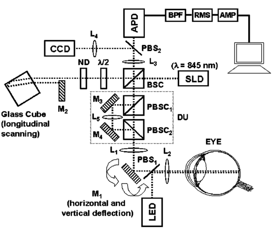
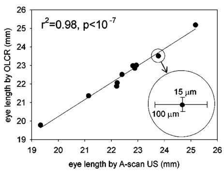
1.IntroductionThe precise and accurate determination of axial eye length is a critical parameter in the preoperative calculation of intraocular lens power during cataract management and in myopia research. Off-axis eye length measurement is also important, given recent interest in retinal contour or eye shape and the role these factors may play in the development of myopia.1 2 3 4 The standard technique for the determination of eye length at present is A-scan ultrasound, which has a maximum precision of only 100 μm (0.1 mm), but this precision is often considerably poorer in clinical settings.5 6 In contrast, optical techniques such as optical coherence tomography (OCT),7 8 partial coherence interferometry (PCI),9 10 11 laser Doppler interferometry (LDI),12 13 and optical low coherence reflectometry (OLCR)14 have become popular because they offer greater precision, often on the order of 3–20 μm. These techniques analyze the intensity of interference fringes created by the superposition of partially coherent light reflected from the ocular surfaces and a reference surface. Compared with ultrasound, they measure axial, intraocular distances with a higher precision and do not require any contact with the eye. OCT is based on a single-beam interferometer; it measures axial distances with respect to an external reference mirror and typically has a longitudinal scanning distance of a few millimeters. It is designed to assess distances between ocular surfaces at either the posterior or anterior areas in the eye, but not between corneal and retinal surfaces, because their separation exceeds the usual scanning distance. Thus OCT can be used to produce high-resolution two-dimensional cross-sections of images of the retina or the anterior ocular segment. However, it does not allow the determination of eye length. In contrast, PCI and LDI are based on a dual-beam interferometer, which uses the cornea as a reference reflector and measures distances with respect to the cornea. They permit the measurement of distances both within and between corneal and retinal surfaces and hence the determination of eye length, even though the typical scanning distance is only about 5 mm, is approximately the same as that of OCT. Eye shape can be determined by measuring eye length in the periphery using off-axis fixation targets10 12 14 or a lateral scanning system.15 The use of the cornea as a reference reflector makes these measurement techniques insensitive to longitudinal eye movements or the distance between the eye and the instrument, which is especially important for follow-up measurements. However, the intensity of the corneal reference reflection is low (≈2 assuming a tear film refractive index of 1.33) compared with the intensity of the OCT reference beam reflected from an external mirror (close to 100 reflection). Because the mean square signal photocurrent 〈IS 2〉 is a function of the optical power PR incident upon the photo detector reflected from the reference arm as illustrated in Eq. (1) where ρ is the detector’s responsivity and PS is the optical power backscattered from the sample,16 〈IS 2〉 is considerably lower in the dual-beam PCI/LDI setup than in the single-beam OLCR setup. The main noise sources expressed in terms of the photocurrent variance σi 2 are σ re 2 (receiver noise), σ sh 2 (shot noise), and σ ex 2 (excess photon noise). Because σ sh 2 and σ ex 2 are proportional to the electronic detection bandwidth B, the signal-to-noise ratio (SNR), defined as SNR=〈IS 2〉/σi 2, is inversely proportional to B.16 Compared with a single-beam interferometer, the power output of the optical source must be increased in a dual-beam interferometer—thereby augmenting 〈IS 2〉 —and/or B must be decreased, for example by narrowing the electronic bandpass filter (BPF) or lowering the scanning speed—thereby decreasing σi 2 —in order to achieve an SNR that permits the detection of the interference signal corresponding to the reflection from the retina. Measuring eye length with dual-beam interferometry suffers from the drawback that the wavefronts that are superimposed for interference are mismatched. The beam reflected from the cornea is divergent, whereas the beam reflected from the retina leaves the eye approximately parallel. The wavefront mismatch reduces the size of the interference fringes, the intensity of the interfering light at the detector, and the SNR compared with a system in which two parallel beams are superimposed. This drawback may be overcome with the application of diffractive optics that allows focusing a part of the incident beam on the cornea while transmitting the other part in parallel.17 18 In order to use the advantage of a strong reference power PR for measuring eye length, I developed a single-beam optical low-coherence reflectometer (OLCR) device using an external reference mirror.19 Although the scanning distance is only about 10 mm, the instrument allows quasi-simultaneous interference signals to be received from both corneal and retinal surfaces and thus to precisely measure eye length. This is achieved with a detour unit that splits the sample beam in two subbeams and recombines them after adding an optical path to one of the subbeams so that a portion of the light reflected from retinal surfaces crosses approximately the same overall optical path length as the light reflected from the cornea. I have further developed and improved the OLCR device by modifying the data analysis algorithm and adding a lateral deflection mechanism that allows assessing on-axis eye length and peripheral eye length (“eye shape”) up to an angle of ±15 deg, not only along the horizontal, but also along the vertical meridian. In this article, the improved OLCR device is described and its technique is validated by comparing axial eye length measured with OLCR device in a group of ten adult eyes with axial eye length measured with A-scan ultrasound in the same eyes, by evaluating the precision in measuring axial length in an adult and in children 7 to 12 years of age, and by analyzing the reproducibility of measuring eye length and shape in an artificial eye and in an adult eye. 2.Description of the OLCR deviceFigure 1 is a schematic drawing of the OLCR device. The parallel beam (diameter=3 mm) of a near-infrared (λ=845 nm) super-luminescent diode (SLD) with a coherence length of approximately 25 μm is split into a sample beam and a reference beam by a beamsplitter cube (BSC). The sample beam is transmitted through a detour unit (DU; for a description see later discussion), a lens system L 1 and L 2, deflected by a mirror M 1 and delivered to the eye. Mirror M 1 deflects the beam horizontally and vertically at normal incidence on the cornea for off-axis measurements. The incident beam is partially reflected at corneal and retinal surfaces and returns to the BSC along the same path as the incident beam. The reference beam is directed to a glass cube with a side length of 30 mm. The beam is refracted at the cube’s surface, twice reflected at inside surfaces, refracted out of the cube, and directed to mirror M 2. Following the reflection at M 2, it is returned on the same path and recombined at the BSC with the sample beam reflected from the eye. The glass cube is rotated at a constant frequency of 3.2 Hz, changing the optical path of the reference beam through the cube and thus the overall optical length of the reference path.20 21 22 Only at the angular cube position where the optical length of the reference path matches the optical length of the sample path reflected from one of the ocular surfaces to within the coherence length of the SLD do the reference and sample parts overlap in time at the BSC and create interference fringes. Lens L 3 images these fringes onto an avalanche photodiode (APD) that measures the light intensity during the cube rotation. Each surface of the cube provides one longitudinal scan. Thus, a cube rotation frequency of 3.2 Hz results in 3.2×4=12.8 longitudinal scans per second. The corresponding longitudinal scanning speed V is approximately 420 mm/s, depending on the orientation of the cube. The scanning speed causes a Doppler shift Δν of the frequency of the reference light by an amount corresponding to Δν=2V/λ∼1 MHz, and one can isolate the interference signal from the total photodetected light with an electronic bandpass filter. The filtered signal is root mean squared (RMS), amplified (AMP), and recorded by a computer as a function of the angular cube position. A light-emitting diode (LED), aligned coaxially with the SLD, is observed through a pellicle beam splitter (PBS 1) and lens L 2. The LED emits light at the visible wavelength of 590 nm and is employed as a fixation target. Normal incidence on the cornea is established by observing the reference and corneal reflections with pellicle beam splitter PBS 2, lens L 4, and a CCD video camera, and shifting the eye laterally until the two reflections superimpose. In order to measure eye length, the OLCR reference beam must be scanned over a distance that encompasses the corneal and retinal areas, that is, at least 33 to 34 mm of optical length in the average adult eye. This required scanning distance and thus the required scanning time, can be reduced considerably with a detour unit (DU; international patent).23 Unlike the configuration described by Podoleanu et al.;24 in which the reference beam is split into two subbeams that are reflected from two reference mirrors mounted at different depths on the same translation stage, the DU splits the sample beam into two separate beams using the polarizing beamsplitter cube PBSC 1. The deflected, s-polarized beam is reflected at mirrors M 3 and M 4, and recombined coaxially with the transmitted, p-polarized beam at the polarizing beamsplitter cube PBSC 2 before the delivery to the eye. When the optical path difference D between the s- and p-polarized beams within the DU matches approximately the optical length of the eye, the portion of s-polarized light reflected from the cornea and the portion of p-polarized light reflected from the retina cross approximately the same overall optical path. As a result, the interference peaks corresponding to reflections from corneal and retinal surfaces are approximately superimposed. Mirrors M 3 and M 4 are mounted on a manual translation stage, which allows the adjustment of D with a Vernier screw. In order to facilitate the distinction—and determination of distance—between corneal and retinal interference peaks, D was adjusted so that their separation measured about 2 mm in a normal eye. The Vernier screw was calibrated with respect to D using a glass plate of known thickness and refractive index. In addition to reducing the scanning distance, the DU has the following advantage: lens L 5 permits one to focus the s-polarized beam on the cornea, which allows the wavefront of the beam reflected from the cornea to be matched with that of the reference beam. This eliminates the need to apply diffractive optics.17 18 Because the reflection from the ocular surfaces approximately maintains the orientation of polarization of the incident light, the s- and p-polarized light reflected from the cornea and retina, respectively, return through the DU on their respective paths with little loss. The orientation of polarization of the reference beam is adjusted with a half-wave plate (λ/2) at an oblique angle to allow for partial interference with both s- and p-polarized light.25 A neutral density filter (ND; transmission T=25) attenuates the intensity of the reference beam in order to maximize the SNR of the interference signal.16 Figure 2 shows an interference signal from the eye of an adult subject. The x-axis indicates the angular cube position converted to optical scanning distance (micrometers). The y-axis indicates the intensity of the interference fringes (volts) as measured by the APD. As the glass cube rotates, the OLCRM consecutively matches the optical distance of the reference beam and the sample beam reflected from various corneal and retinal surfaces, each time generating interference fringes. Therefore the resulting interference signal generally consists of several peaks. The two highest peaks correspond to reflections from the anterior surface of the cornea (AC) and posterior surface of the retina (PR). Note that AC and PR are separated by only about 2 mm. Their separation was defined as reduced eye length (EL*). Eye length (EL) is thereafter obtained by adding the path difference D within the DU to EL*. Amplitudes vary between individual readings owing to eye motion and changes in the tear film. With high-amplitude interference signals, additional peaks are sometimes observed, corresponding to reflections from the posterior corneal (PC) and anterior retinal (AR) surfaces. Figure 2Interference signal from the eye of an adult subject. The peaks correspond to reflections from the anterior and posterior cornea (AC, PC) and anterior and posterior retina (AR, PR). Eye length (EL) is defined as the axial distance from AC to PR. An optical path compensator reduces the scanning distance from AC to PR to a few millimeters (U.S. and international patent).  An eye length measurement consists of seven consecutive scans that are averaged. Data acquisition, visual representation, analysis, and storage are achieved with National Instruments LabVIEW software (National Instruments, Austin, Texas). For off-axis measurements, the sample beam is deviated horizontally and vertically by mirror M 1 while the subject fixates on the stationary LED. The angular precision in position of the sample beam at off-axis locations is approximately ±0.6 deg. After the reflection from mirror M 1, the beam is transmitted through lens L 2, which images the mirror plane onto the approximate location of the corneal center of curvature so that the sample beam falls about perpendicularly onto the cornea regardless of the deviation angle. The maximum deviation angle in the eye, limited by the aperture size of lens L 2, is ±15 deg. To ensure that the sample beam remains parallel at the eye, lens L 1 is placed before mirror M 1 so that it forms a telescope system with lens L 2. 3.Conversion of Optical Length to Geometrical LengthOptical eye length as measured with OLCR is converted to geometrical eye length by dividing the optical distance of each ocular component (cornea, anterior chamber, lens, vitreous chamber) along the measurement axis by the corresponding refractive index. Within the lens, an integration algorithm incorporating the gradient index profile26 needs to be applied. However, neither the individual distances of each component nor their refractive indices at the wavelength of 845 nm are known in an individual eye. As an approximation, the optical properties of Gullstrand’s schematic eye and the dispersion of water are used to convert optical eye length to geometrical eye length as described by Hitzenberger for a wavelength of 780 nm.12 The conversion is based on the assumption that a difference in eye length between Gullstrand’s schematic eye and a measured eye is due to a difference in the vitreous cavity length. Thus, in order to obtain the geometrical length of a measured eye (EL GEO ) at a wavelength of 845 nm, the difference between the optical lengths of the measured eye (EL OPT ) and Gullstrand’s eye (EL G,OPT =32.480 mm) is divided by the refractive index of the human vitreous (n VIT =1.3430) and added to the geometrical length of Gullstrand’s eye (EL G,GEO =24 mm): 4.Number of Scans per MeasurementAs a standard, an eye length measurement consists of seven consecutive scans obtained in less than 1 s. Because of eye movements, poor fixation, or degraded corneal tear film, the number of scans in which both the corneal and retinal signals are detected and hence eye length can be determined, varies among subjects. On average, for subjects with good fixation, normal eye movements, and intact tear film, about four to five scans per measurement yield useful interference signals that allow the determination of eye length with a standard deviation of approximately 15 μm. For other subjects, fewer useful scans per measurement may be obtained and the standard deviation may be higher. If fewer than four scans are obtained that display both the corneal and the retinal reflection as determined by visual inspection of the seven interference signals after a measurement, the measurement is repeated (i.e., another seven scans are obtained) until a total of at least four useful interference signals have been identified. 5.Analysis of the Interference SignalPeak locations—and hence eye length—are determined objectively using a computer algorithm. The algorithm first locates the leftmost interference signal corresponding to the reflection from the anterior corneal surface, and thereafter the highest interference signal to the right corresponding, in most scans, to the reflection from the posterior retinal surface. The separation between the two peaks is added to the known optical path of the DU to obtain eye length. Because the interference signal from the anterior retinal surface exceeds that from the posterior retinal surface in rare instances [see Fig. 3(a)], each scan is visually inspected before eye length is determined and averaged with the algorithm. It can also occur in an individual scan that only the signal peak from AR, but not from PR, is detected. In that case, the operator could misinterpret the signal peak, and the algorithm could measure eye length to the wrong retinal surface. To overcome this difficulty and to confirm the result of an eye length measurement, the individual scans within a measurement are averaged through alignment of the anterior corneal signal [Fig. 3(b)], and the eye length determined in the averaged scan is compared with that determined with the individual scans as a standard procedure of the data analysis. Figure 3In an individual scan (a), the signal from the anterior retina (AR) may be higher than that from the posterior retina (PR). If that occurs, the algorithm erroneously measures the distance AC to AR instead of AC to PR. As a standard procedure to avoid the misinterpretation of a signal peak, eye length determined in the individual scans is confirmed by eye length determined in the averaged scan (b). 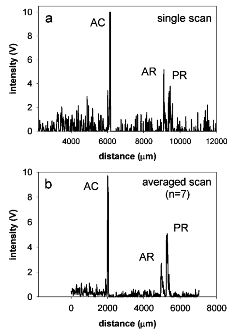 6.Nonlinearity of ScanThe rotating glass cube provides fast longitudinal scans with a high repetition rate. However, unlike a mirror moving at a constant speed, the scanning distance changes nonlinearly with a glass cube rotating at a constant frequency. Within a scanning range from 10 to 45 deg of angular cube orientation, the scanning distance increases faster in the beginning than in the end (Fig. 4). When the interference signal is sampled at constant time intervals using the pulses from an optical encoder attached to the motor of the cube, the scanning distance between consecutive pulses starts with 1.4 μm and ends with 1.0 μm over the scanning range. As a result, the interference signal is distorted with respect to the x-axis, and the measured eye length depends on the location of the interference peaks within the scanning range. Figure 4The relation between the scanning distance and the angular orientation of the cube is not linear (solid line). When the cube rotates with a constant frequency, the scanning distance increases faster in the beginning than in the end of the angular scanning range. For comparison, a linear increase with matching starting and end points is indicated with a dashed line. 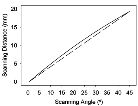 To correct the nonlinearity of the scan, I developed an algorithm that first determines the location of the leftmost major intensity peaks within the interference signal corresponding to the reflection from the anterior cornea and calculates a linearization factor based on the location of that peak within the scanning range. Eye length as determined from the distorted interference signal is thereafter multiplied by the linearization factor. An artificial eye was positioned at three different longitudinal distances from the OLCR device so that the interference peaks were located at the beginning, the middle, and the end of the scanning range, and seven consecutive scans were obtained at each position. Without the linearization factor, eye length measured at the beginning and end of the scanning range differs by 255 μm; with the linearization factors, the difference is reduced to 21 μm. This small but significant difference (p=0.001, one-factor analysis of variance, ANOVA) does not influence the accuracy of the instrument in a major way, because as a standard when eye length is measured, the eye is positioned so that the interference peaks are located in approximately the middle of the scanning range. 7.Laser Safety AnalysisThe OLCR device measurement beam has a wavelength of 845 nm, a diameter of 1.5 mm, and a power of 200 μW at the cornea. According to Table 5a of the ANSI standard,27 the maximum permissible irradiance at the cornea—or maximum permissible exposure (MPE)—in the wavelength range 700 to 1050 nm for viewing periods from 10 to 3×10⁴ s (i.e., sustained viewing) is found by the relationship: MPE=102(0.845−0.700)×10−3 W/cm 2=1.95×10⁻³ W/cm 2. Assuming that the limiting aperture is the dilated pupil with a diameter (d) of 7 mm (Table 8)27 with an area of A=(d/2)2π, the irradiance (E) of the OLCR beam is calculated as Comparing the irradiance E with the calculated MPE gives MPE/E=3.75, a nearly four times safety factor. This analysis shows that the OLCR laser power is safe according to the ANSI Z136.1-2000 standard for direct sustained viewing within the beam.278.Reproducibility of Eye Length MeasurementThe reproducibility of eye length measured with OLCR was assessed in an artificial eye and in the eye of a young adult subject by measuring eye length five consecutive times. The sample beam was used as a fixation target. Between the measurements, the artificial eye and the head of the subject were removed from the chin rest. Both in the artificial eye. [Fig. 5(a)] and the eye of a young volunteer [Fig. 5(b)], OLCR consistently measured the same eye length. The differences between the five measurements were not significant (p=0.89 in the artificial eye, p=0.14 in the adult eye) as estimated with a one-factor ANOVA. The average standard deviation of the five measurements was 10 μm and 25 μm in the artificial and adult eye, respectively. Figure 5The reproducibility of OLCR for measuring eye length in an artificial eye (a) and an adult eye (b). Eye length was measured five times, each time removing the eye from the chin rest. The graph illustrates the averages and the standard deviations of the five measurements. Both in the artificial and the adult eye, eye length was measured consistently the same, albeit the variation in the adult eye was larger than in the artificial eye.  9.Comparison of Axial Length Measurements by OLCR and A-scan Ultrasound in the Same EyesEye length was measured in one eye each of ten adult subjects both with OLCR and A-scan ultrasound. The A-scan ultrasound device displayed the result of a measurement in millimeters with a one-digit precision, and eye length was measured until a reading repeated itself. Eye lengths measured with OLCR and A-scan ultrasound correlated well (r2=0.98, p<10−7; Fig. 6), indicating that the two methods yielded, on average, the same results. The average difference of 40 μm between the optical and acoustic method was not significant (Student’s paired t-test). The precision of OLCR (S.D.=15 μm), however, is at least six times higher than that of A-scan ultrasound (S.D.>100 μm). 10.Precision in Adults versus Precision in ChildrenThe precision of OLCR in measuring eye length largely depends on the capability and cooperation of the subject in fixating on a target. In children, the fixation quality—and hence the measurement precision—most likely differs from that in adult subjects. To evaluate the precision in children, axial eye length was measured with OLCR in 63 children aged 7 to 15 years, and the average standard deviation of multiple readings within a measurement was determined and compared with that obtained in 24 adults aged 22 to 45 years. The mean standard deviation in children was 25±16 μm (mean±S.D.), which is significantly greater than the mean standard deviation of 18±9 μm in adults (p=0.031, unpaired Student’s t-test). Dividing the children into three age groups (7 to 9 years, 10 to 12 years, and 13 to 15 years) and analyzing the differences among the groups with a one-factor ANOVA demonstrated that the precision did not depend on the age of the children. 11.Reproducibility of Eye Shape MeasurementThe reproducibility of eye shape measurement with OLCR was assessed in an artificial eye and in the eye of a young adult subject by measuring eye length three consecutive times along the visual axis and at 15 deg nasally, temporally, inferiorly, and superiorly. Between the measurements, the artificial eye and the head of the subject were removed from the chin rest. In both the artificial and the real eye, eye length differed significantly among the three measurements at several of the assessed locations (Fig. 7) by a maximum of 65 μm in the artificial eye and 86 μm in the adult eye. The differences are most likely due to a ±0.6-deg error in repositioning the sample beam in the eye, resulting in eye length measurements along slightly different axes. These measurements indicate that the shape of the artificial eye and the adult eye differ considerably. Compared with the artificial eye, the adult eye measured for this demonstration showed a flatter shape along the vertical meridian and an asymmetric shape along the horizontal meridian. 12.DiscussionWhen Eq. (3) is used to convert optical eye length to geometrical eye length, OLCR measurements correlate well with A-scan ultrasound measurements in the same eyes. If the optical distances of the individual components in the anterior segment or the refractive indices in a measured eye differ from those in Gullstrand’s eye, an error may be induced during the conversion. Such an error may affect the accuracy of the technique, but not its precision. OLCR permits the precise and noncontact measurement of eye length on-axis and off-axis. It is especially valuable for relative eye length measurements, i.e., for monitoring eye length measured in the same eye at different times or for determining eye shape by comparing off-axis with on-axis measurements. The on-axis precision in a subject with good fixation is approximately 15 μm as estimated from the standard deviation of consecutive scans within a measurement and the variation between consecutive measurements. In children, the precision is lower than in adults, presumably because of poorer fixation, but it is still at least three times higher than that with clinical A-scan ultrasound. An earlier study using LDI reported that eye length measured optically was an average of 470 μm greater than eye length measured acoustically.12 The difference was attributed to the exclusion of retinal thickness and indentation of the cornea by the probe in ultrasound measurements. I did not find a significant difference in OLCR and ultrasound eye length, which is most likely due to an overestimate of the refractive index of the ocular media when optical distance was converted to geometrical distance. The precision in measuring off-axis eye length after repositioning the sample beam is approximately 80 μm, which is most likely due to angular repositioning errors of up to ±0.6 deg at off-axis locations. Eye shapes measured in an artificial and an adult eye differed considerably. The adult eye displayed a flatter and more asymmetric shape than the artificial eye. The asymmetry observed in the adult eye may reflect an irregular topography in the area of the optic nerve head. OLCR allows eye length and shape to be measured with a higher precision than other techniques that have been used to assess human eye shape in vivo, such as X-ray,28 magnetic resonance imaging (MRI),29 and computed tomography (CT).30 Compared with LDI and its commercially available version, the IOLMaster (Carl Zeiss, Inc., Thornwood, New York), the OLCR device scans at a higher repetition rate, which permits the measurement of eye length using seven scans in about 0.6 s. In direct comparison with the IOLMaster, the OLCR device emits at a longer wavelength (850 versus 780 nm), which causes less light scattering in the ocular media, resulting in a greater penetration depth. It also has a shorter coherence length (30 μm versus 120 μm), which permits measurement of eye length and discrimination of reflecting layers within the retina at a higher resolution. Unlike the IOLMaster, the OLCR device does not display artifactual intensity peaks that are caused by the symmetric coherence function of the IOLMaster’s multimode laser diode. Such peaks are sometimes observed at equal distances to the left and right of an actual signal peak and may be confused with signal peaks corresponding to reflections from nearby retinal layers. Finally, the OLCR light has a lower power of 200 μW at the cornea, compared with approximately 400 μW of the IOLMaster. The lower power allows measurements over a longer time period and more consecutive scans, which makes OLCR more suitable for serial measurements of eye length, especially in patients with poor fixation or in children. The capability of the OLCR device to adjust the sample beam’s angle of incidence for off-axis measurements while the subject maintains central fixation avoids the potential danger of confounding eye deformations caused by peripheral gaze.31 In several studies, eye shape was estimated indirectly through the measurement of peripheral refraction using on- and off-axis fixation targets.1 2 3 4 31 32 These indirect measurements are much more influenced by the anterior segment optics, such as astigmatism and aberrations, than those of OLCR, and substantial calculation is required for the estimation of eye shape.33 In conclusion, the high precision and the advantages of OLCR compared with other techniques make it a promising tool for studies on posterior segment dimensions and the role of eye shape in refractive development in children. AcknowledgmentsThe author thanks Felix M. Barker for insightful comments and the preparation of the laser safety analysis. This project was supported by the Swiss National Science Foundation (grant 32-59194.99) and the Pennsylvania Lions Sight Conservation and Eye Research Foundation. REFERENCES
D. O. Mutti
,
R. I. Sholtz
,
N. E. Friedman
, and
K. Zadnik
,
“Peripheral refraction and ocular shape in children,”
Invest. Ophthalmol. Visual Sci. , 41
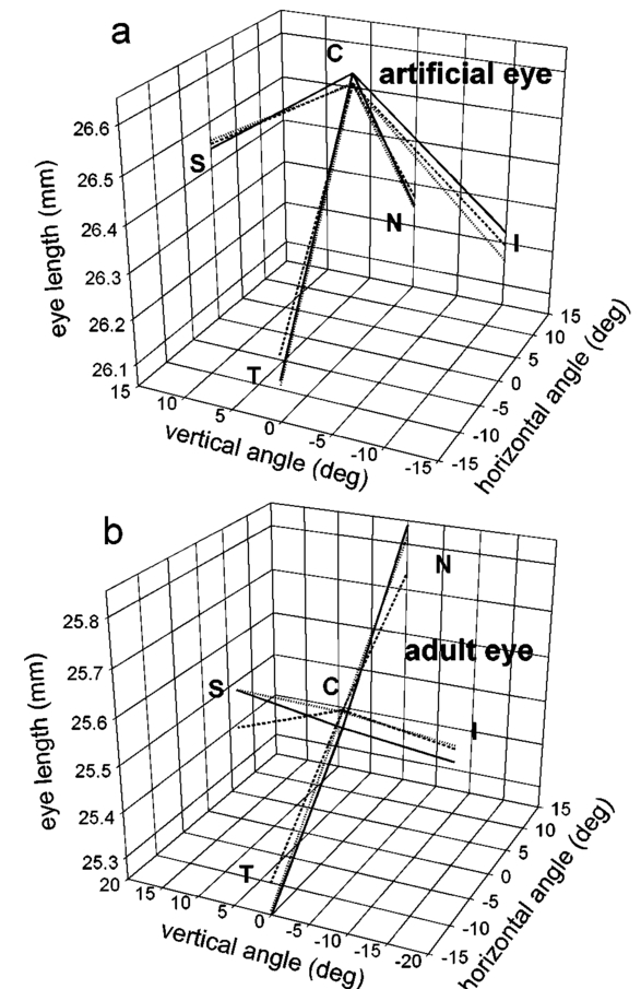
(5), 1022
–1030
(2000). Google Scholar
T. W. Walker
and
D. O. Mutti
,
“The effect of accommodation on ocular shape,”
Optom. Vision Sci. , 79
(7), 424
–430
(2002). Google Scholar
A. Seidemann
,
A. Guirao
, and
P. Artal
,
“Relation of peripheral refraction to refractive development,”
Invest. Ophthalmol. Visual Sci. , 40
(4), S448
(1999). Google Scholar
J. Love
,
B. Gilmartin
, and
M. C. M. Dunne
,
“Relative peripheral refractive error in adult myopia and emmetropia,”
Invest. Ophthalmol. Visual Sci. , 41
(4), S302
(2000). Google Scholar
U. Giers
and
C. Epple
,
“Comparison of A-scan device accuracy,”
J. Cataract Refractive Surg. , 16
(2), 235
–242
(1990). Google Scholar
M. R. Hee
,
J. A. Izatt
,
E. A. Swanson
,
D. Huang
,
J. S. Schuman
,
C. P. Lin
,
C. A. Puliafito
, and
J. G. Fujimoto
,
“Optical coherence tomography of the human retina,”
Arch. Ophthalmol. (Chicago) , 113
(3), 325
–332
(1995). Google Scholar
D. Huang
,
E. A. Swanson
,
C. P. Lin
,
J. S. Schuman
,
W. G. Stinson
,
W. Chang
,
M. R. Hee
,
T. Flotte
,
K. Gregory
,
C. A. Puliafito
, and
J. G. Fujimoto
,
“Optical coherence tomography,”
Science , 254
(5035), 1178
–1181
(1991). Google Scholar
A. F. Fercher
,
K. Mengedoth
, and
W. Werner
,
“Eye length measurement by interferometry with partially coherent light,”
Opt. Lett. , 13 186
–188
(1988). Google Scholar
A. F. Fercher
,
C. K. Hitzenberger
, and
M. Juchem
,
“Measurement of intraocular distances using partially coherent light,”
J. Mod. Opt. , 38 1327
–1333
(1991). Google Scholar
W. Drexler
,
O. Findl
,
R. Menapace
,
G. Rainer
,
C. Vass
,
C. K. Hitzenberger
, and
A. F. Fercher
,
“Partial coherence interferometry: a novel approach to biometry in cataract surgery,”
Am. J. Ophthalmol. , 126
(4), 524
–534
(1998). Google Scholar
C. K. Hitzenberger
,
“Optical measurement of the axial length by laser Doppler interferometry,”
Invest. Ophthalmol. Visual Sci. , 32 616
–624
(1991). Google Scholar
G. F. Schmid
,
B. L. Petrig
,
C. E. Riva
,
K. H. Shin
,
R. A. Stone
,
M. J. Mendel
, and
A. M. Laties
,
“Measurement of intraocular distances in humans and chicks with a precision of better than ±20 μm by laser Doppler interferometry,”
Appl. Opt. , 35
(19), 3358
–3361
(1996). Google Scholar
G. F. Schmid, B. L. Petrig, C. E. Riva, A. M. Laties, M. J. Mendel, and M. C. M. Dunne, “Eye shape and diurnal eye length variation by laser Doppler interferometry,” in Vision Science and its Applications, Vol. 2, pp. 130–133, OSA Technical Digest Series, Optical Society of America, Washington, DC (1994).
W. Drexler
,
C. K. Hitzenberger
,
H. Sattmann
, and
A. F. Fercher
,
“Measurement of the thickness of fundus layers by partial coherence tomography,”
Opt. Eng. , 34
(3), 701
–710
(1995). Google Scholar
A. M. Rollins
and
J. A. Izatt
,
“Optimal interferometer designs for optical coherence tomography,”
Opt. Lett. , 24
(21), 1484
–1486
(1999). Google Scholar
A. Baumgartner
,
C. K. Hitzenberger
,
H. Sattmann
,
W. Drexler
, and
A. F. Fercher
,
“Signal and resolution enhancements in dual beam optical coherence tomography of the human eye,”
J. Biomed. Opt. , 3
(1), 45
–54
(1998). Google Scholar
B. Mo¨ller
,
G. Rudolph
,
A. Klopffleisch
,
K. H. Donnerhacke
, and
A. Dorsel
,
“Application of diffractive optics for axial eye length measurement using partial coherence interferometry,”
Proc. SPIE , 2930 175
–182
(1996). Google Scholar
G. F. Schmid
,
B. L. Petrig
,
C. E. Riva
,
E. Logean
, and
R. Waelti
,
“Measurement of eye length and eye shape by optical low coherence reflectometry,”
Klin. Monatsbl. Augenheilkd. , 216 324
–326
(2000). Google Scholar
X. Clivaz
,
F. Marquis-Weible
,
R. P. Salathe´
,
R. P. Nowak
, and
H. H. Gilgen
,
“High-resolution reflectometry in biological tissues,”
Opt. Lett. , 17
(1), 4
–6
(1992). Google Scholar
C. B. Su
,
“Achieving variation of the optical path length by a few millimeters at millisecond rates for imaging of turbid media and optical interferometry: a new technique,”
Opt. Lett. , 22 665
–667
(1997). Google Scholar
A. G. Podoleanu
,
G. M. Dobre
,
D. L. Webb
, and
D. A. Jackson
,
“Simultaneous en-face imaging of two layers in the human retina by low-coherence reflectometry,”
Opt. Lett. , 22 1039
–1041
(1997). Google Scholar
B. K. Pierscionek
and
D. Y. C. Chan
,
“Refractive index gradient of human lenses,”
Optom. Vision Sci. , 66
(12), 822
–829
(1989). Google Scholar
J. Deller
,
A. O’Connor
, and
A. Sorsby
,
“X-ray measurements of the diameter of the living eye,”
Proc. R. Soc. London , 134 456
–462
(1947). Google Scholar
H. M. Cheng
,
“Magnetic resonance imaging of the human eye in vivo,”
Optom. Vision Sci. , 68
(12), 976
–980
(1991). Google Scholar
F. R. Wang
,
X. D. Zhou
, and
S. Z. Zhou
,
“A CT study of the relation between ocular axial biometry and refraction,”
Chung Hua Yen Ko Tsa Chih , 30
(1), 39
–40
(1994). Google Scholar
C. E. Ferree
,
G. Rand
, and
C. Hardy
,
“Refraction for the peripheral field of vision,”
Arch. Ophthalmol. (Chicago) , 5 717
–731
(1931). Google Scholar
F. Rempt
,
J. Hoogerheide
, and
W. P. H. Hoogenboom
,
“Peripheral retinoscopy and the skiagram,”
Ophthalmologica , 162 1
–10
(1971). Google Scholar
M. C. M. Dunne
,
“A computing scheme for determination of retinal contour from peripheral refraction, keratometry and A-scan ultrasonography,”
Ophthalmic Physiol. Opt. , 15
(2), 133
–143
(1995). Google Scholar
|


CITATIONS
Cited by 39 scholarly publications and 7 patents.
Eye
Cornea
Ultrasonography
Mirrors
Reflection
Electroluminescence
Beam splitters


