|
|
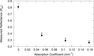
1.IntroductionBasal cell carcinoma (BCC) is the most common form of skin cancer in North America, with over one million new cases diagnosed annually.1 The treatment for BCC can include excision, radiation, cryosurgery, micrographic surgery, or photodynamic therapy (PDT). PDT is an attractive treatment choice, because it selectively targets the tumor cells, resulting in minimal side effects and a good cosmetic outcome.2 PDT also allows for repeat treatments without an increased risk of secondary cancers. PDT is most commonly performed by coupling a laser to a microlens-tipped optical fiber for treatment with a broad beam. The microlens fiber is positioned so that the projected beam completely covers the targeted area. The diameter of the beam and the power emitted from the fiber are used to calculate the treatment time via Eq. 1. The prescribed PDT radiant exposure, measured in incident energy over treatment area, is chosen empirically to maximize the success of the treatment while minimizing adverse reactions for the majority of patients. This does not take into account the wide range of optical properties for human skin, which affect the fluence rate distribution, and can contribute to relatively low treatment success rates: as low as 66% for BCCs.3 These rates might be improved by accounting for the variations in tissue optical properties. Additionally, if the laser power is not sufficient, the treatment times can be long, especially for large treatment fields or multiple sites. This is exacerbated by the loss of a large portion of the incident light through specular and diffuse reflection. If the reflected light were redirected back onto the surface, a greater percentage of the available light would be absorbed by the tissue and the treatment time could be lowered. Both of these concerns can be addressed by the incorporation of an integrating sphere into the irradiation apparatus. An integrating sphere consists of a hollow sphere, with various port openings, coated internally with a highly reflective, diffuse material. Its primary purpose is to contain and diffuse the input light to create a uniform irradiance across the entire internal surface of the sphere.4 This work demonstrates that such spheres improve the efficiency of the light delivery by decreasing the light lost by reflection, and also create flatter, better defined beam profiles. The sphere also provides a means of measuring the tissue optical properties, which may allow for real-time light dosimetry. 2.Materials and Methods2.1.Integrating SphereThe integrating sphere was constructed on site at the Juravinski Cancer Centre (Hamilton, Ontario). The sphere wall was coated with two coats of 6080 diffuse white reflectance coating (Labsphere, North Sutton, New Hampshire) and had a measured reflectivity of . The sphere had a radius of with a radius irradiation port, resulting in a fractional port area of 0.0643. The irradiation port was positioned directly opposite the source fiber port (Fig. 1 ), and the port diameter was selected to encompass the majority of lesion sizes seen clinically. The sphere diameter was chosen so that the divergent beam produced by the microlens overlapped the edges of the port opening by . The overlap ensured that the entire exit port area was irradiated. The divergent beam size was determined by the fiber’s characteristics, confirmed to be the same as provided by the manufacturer (model FD1, Medlight, Switzerland). 2.2.Measurements in Tissue-Simulating PhantomsProfile and depth fluence measurements were performed in a tissue-simulating liquid phantom consisting of a 1% Intralipid® solution (Baxter, Toronto, Ontario). This mixture has a negligible absorption coefficient and a reduced scattering coefficient of at a wavelength of ,5 similar to the mean value of the reduced scattering coefficient measured from the surface of human skin.6, 7, 8 A therapeutic diode laser (630 PDT Laser, Diomed, Andover, Massachusetts) was coupled to the source fiber. This was secured to the top of the sphere so that the tip of the fiber was flush with the sphere’s inner surface. A detection fiber (IP isotropic probe, Medlight, Switzerland) with an isotropic scattering tip was connected to a Newport hand-held optical power meter (Model 840, Irvine, California) and positioned directly below the sphere. Relative light fluence profiles were obtained by taking power measurements across the diameter of the irradiation port at a depth of in increments. This depth was chosen so that measurements would not be affected by potential surface effects. To measure the depth fluence curve, the fiber was positioned at the center of the irradiation port, and measurements were taken starting at the surface and increasing in depth by to a maximum of , or until the power decreased below that of the background. These measurements were repeated with three concentrations of india ink (Regal-LA Reeves Incorporated, Downsview, Ontario) (0.1, 0.2, and 0.3%) added to the Intralipid. The absorption coefficients of the three phantoms (0.053, 0.106, and , respectively) simulate the typical range for human skin found in the literature.6, 7, 8 2.3.Monte Carlo SimulationsTo further characterize the sphere, an existing Monte Carlo (MC) program9 was adapted to launch photons from the top of the sphere, with a direction vector inside the cone defined by the properties of the microlens such that the majority of the photons were incident on the tissue surface. Once inside the tissue, each photon’s weight was scored and reduced following each interaction until it re-entered the sphere or its history was terminated. When inside the sphere, the photons were diffusely scattered by the sphere wall until they were incident on the tissue and either reflected back into the sphere or refracted into the tissue. 2.4.Reflectance Side Port MeasurementsThe integrating sphere was equipped with a side port with an SMA fiber connector. An optical fiber was connected to a power meter and was used to monitor the power. Power readings were recorded from this port, first with the irradiation port covered by a calibration plate made of the same material and coated with the same paint as the sphere, and then with the sphere positioned over the Intralipid phantom (Sec. 2.2). The phantom measurement was divided by the calibration measurement to yield a unitless reflectance . These reflectance measurements were mimicked in the MC simulations by estimating the irradiance on the inner wall of the sphere, both when the irradiation port was over tissue, and when the tissue was replaced by a flat surface with reflectance properties identical to the sphere wall. These “tissue” and “calibration” readings yielded a unitless reflectance that could be compared to that measured on the phantoms. 2.5.In Vivo Surface MeasurementsTo determine the ratio of fluence rates with and without the sphere in vivo, and to investigate whether superficial measurements with the sphere were predictive of the relative fluence at depth, surface measurements were taken on the forearms of volunteers. An isotropic detector was attached to each volunteer’s forearm in the broadest and palest region using hypoallergenic tape. This location was chosen for its relative uniformity in color, texture, and for its lack of hair. The treatment fiber was connected to a white light source and the isotropic detector fiber was connected to a spectrometer (SD 2000, Ocean Optics, Dunedin, Florida). The sphere was positioned so that the isotropic detector was in the center of the irradiation port and the surface fluence was recorded. The treatment fiber was subsequently fixed the same distance from the skin without the sphere in place, and the surface fluence measurement was repeated. The quotient of these two values yielded the relative fluence. This protocol was approved by the Hamilton Health Sciences/Faculty of Health Sciences Research and Ethics Board. 3.Results3.1.Contour PlotsTo visualize the effects of the integrating sphere, isofluence-rate contours were constructed from the MC simulation data. These plots were not generated for the measurements in phantoms because the data were too sparse. The contour plots from the MC data for optical properties equivalent to a 1% Intralipid phantom are shown in Fig. 2 . The fluence rates were normalized to unit power emitted from the source fiber [resulting in units of ]. Fig. 2Contour plots of normalized isofluence calculated by Monte Carlo simulations for a 1% Intralipid phantom: (a) without the integrating sphere in place over the tissue and (b) with the integrating sphere in place over the tissue. Units for the contour labels are . 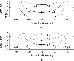 The contour plots show that the sphere had significant effects on the fluence rate distribution. The fluence rate increased and the depth of the isoline increased from approximately . Additionally, the radius of this isoline at the surface was smaller and confined to the radius of the port opening. 3.2.Fluence Profile and Depth MeasurementsA more detailed understanding of the effects of the sphere was permitted by analysis of the fluence rate profile and depth data. Typical curves are shown in Figs. 3 and 4 . The increase in fluence rate is seen in the depth fluence rate as a vertical shift of the “with sphere” curve. In the profile curves, the introduction of the sphere resulted in an increase in the fluence rate. Fig. 3Semilogarithmic depth fluence curves, with (upper curve) and without (lower curve) the sphere in place over a 1% Intralipid phantom with 0.01% india ink from: (a) the phantom measurements and (b) the MC simulation.  Fig. 4Fluence profiles at a depth of , with (upper curve) and without (lower curve) the sphere in place over a 1% Intralipid phantom from: (a) the phantom measurements and (b) the MC simulation.  To quantify the effect of the integrating sphere on the fluence profiles, the following terms, borrowed from radiation therapy, were used. The field size was defined as the distance between the 50% of maximum values on the profile curve. The 80% flatness represents the absolute percent deviation from the central axis value across 80% of the field size. The 80 to 20 penumbra was the distance required for the fluence to drop from 80% of its central axis value to 20%. The relative fluence is the ratio of the central axis fluence rates with and without the sphere in place at a specific depth. These parameters are listed in Table 1 for each of the Intralipid/india ink phantoms. Table 1Fluence profile parameters for the phantom measurements and MC simulation at a depth of 3m .
The average field size at a depth of was (phantom) and (MC) without the sphere, and (phantom) and (MC) with the sphere. The ink concentration had no effect on the field size. The sphere restricts light to the irradiation port at the surface , and this reduced field size was maintained even at a depth of . The sphere created a more uniform beam profile, as indicated by the smaller flatness. The flatness also improved as the absorption coefficient increased. The penumbra decreased when the sphere was in place, contributing to a sharper, more defined edge to the treatment field. This value also decreased with ink concentration. There was a significant increase in the light fluence rates when the sphere was employed. The relative fluence was as high as 1.8 (phantom) and 2.0 (MC), and decreased steadily as the absorption coefficient increased, to minimum values of 1.5 and 1.3. This was because a larger percentage of the incident light was absorbed, and therefore less light was reflected back into the sphere, reducing the ratio. The relative fluence was also calculated from the depth fluence measurements. These data were fitted to an exponential function with an exponential constant equal to the effective attenuation coefficient (data not shown) and a multiplicative constant. Since the optical properties were the same in both scenarios, only the multiplicative constant varied. The ratio of these fitted constants was the relative fluence. The relative fluence from the depth fluence curves and the profile curves are shown in Fig. 5 . Each of the four sets of data shows the same relationship between the relative fluence and the absorption coefficient of the tissue. Fig. 5Relative fluence as a function of absorption coefficient for the depth fluence and profile curves. For clarity, error bars are only shown on the phantom profile data. 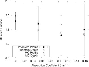 The large relative uncertainties in the phantom measurements were the result of uncertainty in determining the depth. Surface tension in the liquid phantom made it difficult to determine when the probe was actually at depth zero. This uncertainty resulted in larger uncertainties in the fluence rate, especially at greater ink concentrations where the fluence gradient was steeper. This uncertainty was not present in the MC simulations, since the depth was strictly defined, and the corresponding error bars are appreciably smaller. 3.3.Reflectance MeasurementsThe measured side port reflectance from the phantom and the MC simulations is shown in Fig. 6 . Both decreased as the absorption coefficient increased, similar to the trend of the relative fluence as a function of the absorption coefficient. They also agree very closely, though the phantom value is consistently slightly larger than the MC value. 3.4.In Vivo MeasurementsRelative fluence measurements were performed on the forearms of 21 volunteers with a variety of skin types ranging from very fair (type 1 on the Fitzpatrick scale)10 to very dark (type 6). The relative fluence (with sphere/without sphere) ranged from 1.67 to 3.00 at with a mean of 2.26 and a median of 2.27. These values are considerably higher than those measured at depth in the phantom (1.30 to 2.00). The spectral relative fluence for six of the volunteers is shown in Fig. 7 . These sample curves were chosen to show the range in relative fluence for the six skin types on the Fitzpatrick scale. It is clear that larger relative fluence corresponds to lighter skin color (lower absorption coefficients). The curves for subjects with lighter skin also have local minima at approximately 540 and , which correspond to absorption peaks of oxyhemoglobin.11 Over the measured spectral range, there are no local features due to melanin,12 but the entire relative fluence curve is shifted vertically as the melanin concentration is reduced. 3.5.Treatment TimeIn Sec. 3.3, it was shown that an integrating sphere can increase the light fluence rate for a PDT treatment, but that the improvement depended on the absorption coefficient. Irradiating for the same treatment time with the sphere in place will result in patients receiving different surface light doses, depending on their individual tissue optical properties. If the patient-specific increase in fluence rate were known, the treatment time could be adjusted accordingly, providing individualized dosimetry and, perhaps, more consistent treatment results. The increase in fluence rate in the tissue is the result of reflected light redirected back onto the skin surface. The amount of reflected light should be related to the reflectance measured through the side port, and could, in principle, be used to predict the interstitial fluence rate change. To test this hypothesis, MC simulations were performed with a range of absorption and reduced scattering coefficients, and the relative fluence and reflectance were calculated as described previously. These results are shown in Fig. 8 . When the scattering coefficient was held constant and the absorption coefficient was increased, the relative fluence decreased, as previously seen. Conversely, when the absorption coefficient remained constant and the scattering coefficient was increased, the relative fluence increased. When the relative fluence was plotted against the side port reflectance, a strong linear relationship was evident (see Fig. 9 ), described by, where the uncertainties are estimated from the least-squares linear fit.Fig. 8Relative fluence as a function of absorption coefficient for different reduced scattering coefficients.  Fig. 9Relative fluence as a function of reflectance. The data were fitted with the linear relationship shown in Eq. 2.  4.Discussion4.1.Characterization of Sphere EffectsThe contour plots, profile, and depth fluence curves confirm that the sphere is effective at increasing the light fluence rates in tissue. In the contour plots, this was evident in a shift of the isofluence lines roughly deeper into the tissue. In the profile curves, this was seen by an increase in the central axis fluence value at a depth of , ranging from 30 to 100%, depending on the absorption coefficient of the tissue. Finally, in the depth fluence curves, this was indicated by the constant fractional increase in fluence measured at each depth. The sphere was also successful at improving the beam characteristics. Profiles with the sphere in place showed an improvement in flatness across the field size as well as a reduction in the penumbra, allowing for a better defined, more uniform treatment field. The field size at a depth was sufficiently described by the size of the irradiation port. This is important, because it indicates that the treatment area is sufficiently illuminated at depth. 4.2.In Vivo ResultsThe hemoglobin spectral features and the variation with skin types of the relative fluence curves from Fig. 7 indicate that the efficacy of the sphere is dependent on the skin’s optical properties which, in turn, are dependent on the concentrations of melanin and oxyhemoglobin. The relative fluence measured on the surface of the skin on volunteers’ forearms was up to 50% higher than the values determined from the phantom and MC data at depth. These results were confirmed with MC simulations in which an isotropic “detector” was located just above the tissue surface. This difference was not investigated in further detail, as the subsurface fluence rate is the clinically relevant parameter. When the sphere was positioned over the treatment area, it was observed that the treatment was no longer sensitive to patient movement, as the direct contact of the sphere with the tissue prevented any misalignment. 4.3.Treatment TimeAs discussed in Sec. 3.4, it was hypothesized that the relative fluence could be predicted from the reflectance measurement. This was investigated by running additional MC simulations with different combinations of absorption and reduced scattering coefficients. It was shown that the relative fluence increased monotonically with the reduced scattering coefficient, while the reverse behavior was seen with the absorption coefficient. These observations are consistent with the fact that, for a given index of refraction, the diffuse reflectance from a semi-infinite volume of tissue depends solely on the transport albedo, When the relative fluence was plotted as a function of the side port reflectance, a strong linear relationship (Fig. 9) was observed. This relationship can be explained using the integrating sphere theory. The first assumption is that a fraction of the initial irradiance incident on the tissue is reflected back into the integrating sphere. This fraction depends on the optical properties of the tissue and the diameter of the irradiation port. The second assumption is that a second fraction of the light remitted into the sphere is reflected back onto the tissue. If this process were to continue, allowing for multiple reflections from and back into the tissue, the fluence rate with the sphere in place becomes the sum of an infinite series, yielding a relative fluence of,The irradiance on the inner surface of the sphere is calculated in a similar way,The reflectance is calculated by dividing the irradiance with the sphere over tissue by the irradiance when the sphere is over the calibration plate (with a reflectance , where is the measured sphere wall reflectance), which would be,The measured side port reflectance is then defined as,Combining Eqs. 4, 7 results in a relationship between the relative fluence and the side port reflectance,which agrees with the empirical, linear relation expressed in Eq. 2.To test this, was calculated from the Monte Carlo data by tracking the average number of reflections inside the sphere. For the sphere geometry used in this set of simulations, each photon that re-enters the sphere is reflected off the sphere wall 16 times before reaching the irradiation port. Combined with a measured sphere wall reflectance of , this yields a value for of . With these results, the slope of the fitted value from Eq. 2 of is similar to the calculated slope of the line from Eq. 8 of . The fitted -intercept of is also close to the theoretical -intercept of 1. These results indicate that the patient-specific relative fluence for any given sphere can be determined from the reflectance, using Eqs. 2, 8. The parameters in these equations are dependent on the sphere geometry but can be determined empirically. The treatment time can be adjusted accordingly. 4.4.Penetration DepthThe previous results raised the question whether the reflectance measurements could also be used to determine the penetration depth in the skin. This would be beneficial for dosimetry, as it would allow the treatment time to be adjusted to ensure that the entire thickness of the tumor is irradiated to a minimum fluence, Eq. 6 indicates that the measured reflectance can be used to determine the tissue reflectance . To investigate the relationship between and , the diffuse reflectance coefficient was calculated using the tissue optical properties from the MC simulations and Eq. 9.13 where is defined as the internal reflection parameter. A linear relationship was obtained (not shown). Therefore, there should be a strong correlation between the transport albedo and side port reflectance. This is shown in Fig. 10 . With a sphere geometry that has previously been characterized, it would be possible to calculate the transport albedo from the measured reflectance. This correlation will depend on the specific sphere geometry. A second set of simulations was run for a different sphere geometry to illustrate this dependence. These results are also shown in Fig. 10.Fig. 10Transport albedo as a function of reflectance. The open squares represent the original sphere geometry ( and ), and the closed circles represent another sphere geometry ( and ). 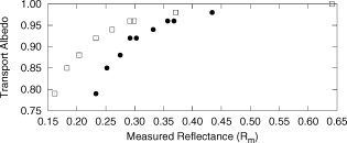 The penetration depth is calculated as the reciprocal of the effective attenuation coefficient , where in the case of the diffusion limit. As such, the absorption and scattering coefficients cannot be determined independently from the albedo. However, if the scattering coefficient were known a priori, the absorption coefficient could be calculated and the effective attenuation coefficient and penetration depth could be determined. If the reduced scattering coefficient is not known in advance, typical values taken from the literature might provide a reasonable estimate of the penetration depth. This could be used in conjunction with the laser power and treatment time to determine the fluence at a specific depth. This would be an ideal light dose metric, as it would remove the effects of different tissue optical properties that currently limit treatment efficacy, and it would be defined at a more clinically relevant location. To test this, the transport albedo and the penetration depth were calculated for a set of optical properties typical for skin. The reduced scattering coefficient was increased by 25%, and the previously calculated transport albedo was used to calculate an absorption coefficient. The incorrect scatter and absorption coefficients were then used to calculate a penetration depth. The difference between this and the actual penetration depth was 36%, resulting in an uncertainty of less than . Given that the penetration depth can vary by up to ,14 knowing this value to within one millimeter would still be useful in PDT dosimetry. 5.ConclusionsIt is demonstrated that the incorporation of an integrating sphere improves the efficiency of the light delivery system for superficial PDT treatments. Contour plots show an increase in the overall fluence rate compared to the current treatment setup. The profile curves demonstrate that the sphere not only increases the fluence rate, but also improves the beam flatness, reduces the penumbra, and creates a more uniform light field. Both the profile and depth data confirm that the relative fluence diminished as the absorption coefficient of the tissue increased. However, even for the highest absorption coefficient, the sphere is still able to increase the fluence rate by 30%. Measurements taken on the forearms of volunteers confirm the previously observed results that the sphere’s effectiveness depends on the tissue optical properties. The range of relative fluence values at the surface is, on average, 50% greater than those measured at depth. This difference is confirmed by MC simulation but is not investigated further. Since the sphere is positioned directly on the tissue, the sensitivity of the treatment to patient movement is minimized. The side port of the integrating sphere is used to measure the reflectance, which can be used to determine the patient-specific relative fluence. This information could be used to adjust the treatment time accordingly, potentially providing more personalized treatments. If a population average for the reduced scattering coefficient is known, the reflectance can also be used to approximate the penetration depth in the tissue. This information could be used to calculate a better light dose metric (such as fluence at a specified depth) that would incorporate differences in patient optical properties and possibly improve treatment efficacy. The incorporation of an integrating sphere into the PDT treatment of superficial skin cancers not only improves the light fluence and treatment field geometry, it may also allow for real-time dosimetry through the side port reflectance measurements. This would lead to more personalized, and potentially more successful, treatments. It may also be possible to treat multiple lesions simultaneously using several spheres connected to the same light source. AcknowledgmentsThe authors would like to thank Greg Sawesky from the Juravinski Cancer Centre’s Mold Room for fabricating the integrating spheres. This work was financially supported by the Ontario Cancer Research Network. References“Cancer Facts and Figures 2009,”
(2009) Google Scholar
L. R. Braathen,
R. Szeimies,
N. Basset-Seguin,
R. Bissonnette,
P. Foley,
D. Pariser,
R. Roelandts,
A. Wennberg, and
C. A. Morton,
“Guidelines on the use of photodynamic therapy for nonmelanoma skin cancer: An international consensus,”
J. Am. Acad. Dermatol., 56
(1), 125
–143
(2007). https://doi.org/10.1016/j.jaad.2006.06.006 0190-9622 Google Scholar
E. S. Marmur,
C. D. Schmults, and
D. J. Goldberg,
“A review of laser and photodynamic therapy for the treatment of nonmelanoma skin cancer,”
Dermatol. Surg., 30
(2), 264
–271
(2004). https://doi.org/10.1111/j.1524-4725.2004.30083.x 1076-0512 Google Scholar
“Integrating sphere design and applications,”
(2007) Google Scholar
S. T. Flock,
S. L. Jacques,
B. C. Wilson,
W. M. Star, and
M. J. C. van Gemert,
“Optical properties of intralipid: A phantom medium for light propagation studies,”
Lasers Surg. Med., 12
(5), 510
–519
(1992). https://doi.org/10.1002/lsm.1900120510 0196-8092 Google Scholar
R. Zhang,
W. Verkruysse,
B. Choi,
J. A. Viator,
R. Jung,
L. O. Svaasand,
G. Aguilar, and
J. S. Nelson,
“Determination of human skin optical properties from spectrophotometric measurements based on optimization by genetic algorithms,”
J. Biomed. Opt., 10 024030
(2005). https://doi.org/10.1117/1.1891147 1083-3668 Google Scholar
V. Tuchin,
“Optical parameters of skin,”
Tissue Optics: Light Scattering Methods and Instruments for Medical Diagnosis, 13 SPIE Press, Bellingham, WA
(2000). Google Scholar
W. F. Cheong,
S. A. Prahl, and
A. J. Welch,
“A review of the optical properties of biological tissues,”
IEEE J. Quantum Electron., 26
(12), 2166
–2185
(1990). https://doi.org/10.1109/3.64354 0018-9197 Google Scholar
T. J. Farrell,
M. S. Patterson, and
M. Essenpreis,
“Influence of layered tissue architecture on estimates of tissue photobleaching for photodynamic therapy dosimetry,”
Appl. Opt., 37
(10), 1958
–1972
(1998). https://doi.org/10.1364/AO.37.001958 0003-6935 Google Scholar
T. B. Fitzpatrick,
“Soleil et peau,”
J. Med. Ethics, 2 33
–34
(1975). 0306-6800 Google Scholar
B. C. Wilson and
M. S. Patterson,
“The physics, biophysics, and technology of photodynamic therapy,”
Phys. Med. Biol., 53
(9), R61
–R109
(2008). https://doi.org/10.1088/0031-9155/53/9/R01 0031-9155 Google Scholar
N. Kollias,
“The spectroscopy of human melanin pigmentation,”
Melanin: Its Role in Human Photoprotection, 31
–38 Valdenmar Publishing Company, Overland Park, KS
(1995). Google Scholar
T. J. Farrell,
M. S. Patterson, and
B. Wilson,
“A diffusion theory model of spatially resolved, steady-state diffuse reflectance for the noninvasive determination of tissue optical properties in vivo,”
Med. Phys., 19
(4), 879
–888
(1992). https://doi.org/10.1118/1.596777 0094-2405 Google Scholar
S. L. Jacques,
“Simple optical theory for light dosimetry during PDT,”
Proc. SPIE, 1645 155
–165
(1992). https://doi.org/10.1117/12.60938 0277-786X Google Scholar
|
||||||||||||||||||||||||||||||||||||||||||||||||||||||||||||||||||||||||||||||||||||||||||||||||