|
|
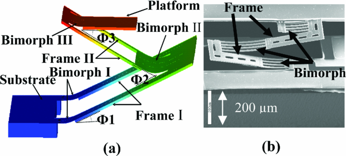
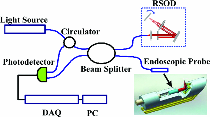
1.IntroductionOptical coherence tomography (OCT) is a fast developing technology capable of high-resolution cross-sectional imaging of highly scattering media.1 It has been widely used for medical imaging in eye and skin diseases due to its high resolution (<10 μm) and noninvasive nature. 2, 3 OCT has also been demonstrated to be very useful in examining internal organs.4 To realize endoscopic OCT imaging, miniature probes with fast optical scanning mechanisms embedded must be developed. Several endoscopic OCT probes have been reported. 5, 6, 7, 8, 9, 10, 11, 12, 13 Those optical fiber-based catheter probes need either rotating or translating motors at the proximal end, 5, 6, 7 or swinging modules at the distal end.8 Slow scan is a common issue for proximal end fiber-based probe because of the friction or vibration of the external motors. For example, a circumferential scanning OCT probe using a fiber optic rotary joint as the scanning mechanism has a low scanning speed of only a few Hz (Ref. 5). A forward-view OCT probe with a pair of angled GRIN lenses and two dc motors rotating at the proximal end of the probe scans at only 21 rpm.6 A linear scanning probe by a galvanometer translates the distal fiber tip at up to 30 Hz and is limited to one-dimensional scan.7 A fast scanner with the distal tip of a fiber excited to its resonance by a piezoelectric actuator for one-dimensional 1.4 kHz scan was reported,8 but swinging the fiber tip might cause significant coupling nonuniformity and coupling loss especially at large angle. MEMS-based endoscopic probes can provide fast scan and uniform coupling. Several MEMS-based probes with diameters ranging from 2.8 to 6 mm have been reported. 9, 10, 11, 12, 13, 14 For example, the authors previously demonstrated an endoscopic OCT probe with a diameter of 5.8 mm (Ref. 14). However, for endoscopic imaging of some internal organs such as human esophagus, further miniaturized probes are needed so that they can fit into the 2.8 mm biopsy channels of standard gastrointestinal (GI) endoscopes.5 In this paper, we present a highly miniaturized endoscopic OCT probe with the diameter of only 2.6 mm. This is the smallest MEMS mirror-based OCT probe reported so far. The probe could be easily integrated with an OCT to form an endoscopic OCT system. The MEMS mirror with through-silicon vias not only allows smaller probe diameter but also eases wire bonding and probe assembling. This miniature probe, providing large scanning angle (±16°) and fast scanning speed (resonance at 659 Hz) at low voltage (less than 3.6 V), is especially attractive for in vivo endoscopic OCT imaging. In the following we will first introduce the MEMS mirror, and then describe the OCT probe design and assembly, followed by OCT imaging experiments. 2.MEMS MirrorAs illustrated in Figs. 1a and 1b, the MEMS mirror is comprised of a mirror plate and four identical bimorph actuators supporting the mirror plate on four sides. There are four through-silicon vias (TSVs) symmetrically located at the four corners of the mirror device and four pads sitting next to the TSVs. These TSVs allow electrical wires to go through from the back side and be bonded to the pads, which eases the bonding and saves space. The bimorph actuators are based on the lateral-shift-free (LSF) large-vertical-displacement (LVD) actuator design as reported in Ref. 15. Each actuator has three Al/SiO2 bimorphs and two rigid frames connected in between, as shown in Figs. 2a and 2b. The bimorphs and frames are arranged in a folded fashion to reduce the actuator area and thus increase the fill factor. Lateral shift and tilting are minimized by properly selecting the lengths of the bimorphs and frames. The device design and dimension optimization can be found in Ref. 15. The mirror is electrothermally actuated, with Pt as the heater embedded along all bimorphs and frames for uniform heating. The device is fabricated using a combined surface- and bulk-micromachining process that is reported in Ref. 15. The mirror aperture size is 0.8 mm × 0.8 mm and the device footprint is 1.5 mm × 1.5 mm. Fig. 1a shows a scanning electron microscope (SEM) image of a fabricated TSV micromirror. The bimorph beams curl upward after release due to the residual stress and will bend downward under electrothermal actuation. Tip-tilt motion can be generated by differentially driving two opposite actuators and the piston motion by simultaneously driving all four actuators. The mirror demonstrates optical scan angle of ±16° at 3.6 V DC as shown in Fig. 3. The angle-versus-voltage response is not linear at low voltage, and becomes linear after a critical voltage. The linear response is caused by the combination of temperature-dependent resistance and voltage-squared dependence of the produced heating power, which can be explained by an electrothermalmechanical lumped element model reported in Ref. 16. The resonance frequency of 659 Hz is observed for the device. 3.MEMS-based OCT ProbeThe miniature OCT endoscopic probe consists of a TSV interconnect MEMS mirror, a GRIN lens, a single-mode fiber and a metal mount base, as shown in Fig. 4a. The single mode fiber (corning SMF-28) delivers the light to the probe. The GRIN lens (NSG America ILW-0.7) focuses the light from the fiber to a small spot size. After the GRIN lens, the 2D MEMS mirror deflects the light out of the probe and scans the sample in x- and y-axis. The returning light is collected by the MEMS mirror, which is directed to the GRIN lens and then coupled back to the single mode fiber. Fig. 4OCT probe: (a) 3D model of the endoscopic OCT probe design, (b) assembled MEMS OCT probe, and (c) packaged MEMS OCT probe.  The fiber tip is cut with an 8° angle to avoid the back-reflection. The fiber and GRIN lens are glued to their grooves in the probe and precisely aligned. The MEMS mirror is fixed into a 0.5-mm-deep square cavity which is slanted at 45° to the central axis of the probe. There are five through-holes in the metal mount. Five copper wires are inserted through these through-holes from the backside of the probe. Four of them go through the TSVs of the mirror chip from the backside and are connected to the pads of the four actuators on the front side. The fifth wire is connected to the ground pad of the mirror. The electrical connection is accomplished using silver epoxy. After all these steps are finished, the loaded probe is slipped into a flexible biocompatible transparent fluorinated ethylene propylene (FEP) tube. The length of the metal mount is the 10.7mm. A wood stick is used to form a rigid part of the probe. The diameter and the length of the GRIN lens are 0.7 mm and 2 mm, respectively. The pitch number is 0.27. The focal length of the GRIN lens is 5 mm. The working distance, i.e., the distance from the outer wall of the probe to the focal point of the light beam, is designed to be 1.5 mm in air. The outer diameter of the probe is measured to be 2.6 mm. Figure 4b shows a loaded probe and Fig. 4c shows a picture of a packaged probe inside the FEP tube. 4.OCT SystemOCT imaging with the MEMS probe was experimentally demonstrated using a time-domain OCT system. As shown in Fig. 5, the endoscopic OCT system is comprised of a broadband light source, a 2 × 2 fiber-based beam splitter, a circulator, a balanced photodetector, a rapid scanning optical delay line (RSOD), and a MEMS-based imaging probe. The light source (DenseLight, DL-BX9-CS3159A) has a central wavelength of 1310 nm with the full width half maximum (FWHM) bandwidth of 75 nm, which corresponds to a 10 μm axial resolution in air. Light is divided by the beam splitter into two paths, i.e., a reference arm and a sample arm. The RSOD in the reference arm provides the depth scan, with a scanning rate of 1 kHz and an effective optical path scan range of 1.6 mm. A carrier frequency of 500 kHz is generated by laterally shifting a rapid scanning mirror in the RSOD. The measured sensitivity of the system is 53 dB. Interference signals are acquired by a data acquisition card and processed by a computer. Two images are acquired for each period, one from the forward scan and one from the backward scan. The frame rate of this system is 2.5 frames/s. 5.Imaging ResultsThe MEMS-based imaging probe has been integrated into the sample arm of the time-domain OCT system for imaging experiments. The depth scan is done by the RSOD. The 2D lateral scan is performed by differentially driving one pair of opposite actuators for fast axis scan and the other pair for slow axis scan. The driving voltages for the fast axis and slow axis are respectively a 1.25 Hz 0–4 V ramp waveform and a 2 mHz 0–4 V ramp waveform. 2D and 3D OCT images of microspheres embedded in PDMS and an acute rat brain tissue have been performed to show the capability of this MEMS-based probe, which are shown in Figs. 6 and Fig. 7, respectively. The size of the polystyrene microspheres is about 20 μm. The microspheres are embedded in a transparent PDMS. The corpus callosum region of the acute brain tissue is imaged. The brain tissue is sliced to about 400 μm in thickness. The scan depth is 1.6 mm. Fig. 62D cross-sectional OCT images: (a) microspheres embedded in PDMS, (b) rat brain tissue. The imaging sizes of (a) and (b) are 800 μm × 1.6 mm and 400 μm × 1.6 mm, respectively. The image sizes are different under the same drive because the samples are placed at different distances from the probe.  6.ConclusionsA miniaturized endoscopic OCT probe based on a through-silicon-via 2D MEMS mirror has been designed, fabricated and packaged. 2D and 3D OCT imaging with the endoscopic probe has been demonstrated. The 2.6 mm probe is very promising for endoscopic OCT imaging of internal organs. This work is supported by the National Science Foundation under award#0901711. ReferencesD. Huang, E. A. Swanson, C. P. Lin, J. S. Schuman, W. G. Stinson, W. Chang, M. R. Hee, T. Flotte, K. Gregory, and
C. A. Puliafito,
“Optical coherence tomography,”
Science, 254
(5035), 1178
(1991). https://doi.org/10.1126/science.1957169 Google Scholar
M. R. Hee, J. A. Izatt, E. A. Swanson, D. Huang, J. S. Schuman, C. P. Lin, C. A. Puliafito, and
J. G. Fujimoto,
“Optical coherence tomography of the human retina,”
Arch. Ophthalmol., 113
(3), 325
(1995). Google Scholar
J. Welzel, E. Lankenau, R. Birngruber, and
R. Engelhardt,
“Optical coherence tomography of the human skin,”
J. Am. Acad. Dermatol., 37
(6), 958
–963
(1997). https://doi.org/10.1016/S0190-9622(97)70072-0 Google Scholar
G. J. Tearney, M. E. Brezinski, B. E. Bouma, S. A. Boppart, C. Pitris, J. F. Southern, and
J. G. Fujimoto,
“In vivo endoscopic optical biopsy with optical coherence tomography,”
Science, 276
(5321), 2037
(1997). https://doi.org/10.1126/science.276.5321.2037 Google Scholar
H. L. Fu, Y. Leng, M. J. Cobb, K. Hsu, J. H. Hwang, and
X. Li,
“Flexible miniature compound lens design for high-resolution optical coherence tomography balloon imaging catheter,”
J. Biomed. Opt., 13 060502
(2008). https://doi.org/10.1117/1.3037340 Google Scholar
J. Wu, M. Conry, C. Gu, F. Wang, Z. Yaqoob, and
C. Yang,
“Paired-angle-rotation scanning optical coherence tomography forward-imaging probe,”
Opt. Lett., 31
(9), 1265
–1267
(2006). https://doi.org/10.1364/OL.31.001265 Google Scholar
V. X. D. Yang, M. Gordon, S. Tang, N. Marcon, G. Gardiner, B. Qi, S. Bisland, E. Seng-Yue, S. Lo, and
J. Pekar,
“High speed, wide velocity dynamic range Doppler optical coherence tomography (Part III): in vivo endoscopic imaging of blood flow in the rat and human gastrointestinal tracts,”
Opt. Exp., 11
(19), 2416
–2424
(2003). https://doi.org/10.1364/OE.11.002416 Google Scholar
X. Liu, M. J. Cobb, Y. Chen, M. B. Kimmey, and
X. Li,
“Rapid-scanning forward-imaging miniature endoscope for real-time optical coherence tomography,”
Opt. Lett., 29
(15), 1763
–1765
(2004). https://doi.org/10.1364/OL.29.001763 Google Scholar
Y. Pan, H. Xie, and
G. K. Fedder,
“Endoscopic optical coherence tomography based on a microelectromechanical mirror,”
Opt. Lett., 26
(24), 1966
–1968
(2001). https://doi.org/10.1364/OL.26.001966 Google Scholar
W. Jung, D. T. McCormick, J. Zhang, L. Wang, N. C. Tien, and
Z. Chen,
“Three-dimensional endoscopic optical coherence tomography by use of a two-axis microelectromechanical scanning mirror,”
Appl. Phys. Lett., 88 163901
(2006). https://doi.org/10.1063/1.2195092 Google Scholar
Y. Xu, J. Singh, C. Premachandran, A. Khairyanto, K. Chen, N. Chen, C. Sheppard, and
M. Olivo,
“Design and development of a 3D scanning MEMS OCT probe using a novel SiOB package assembly,”
J. Micromech. Microeng., 18 125005
(2008). https://doi.org/10.1088/0960-1317/18/12/125005 Google Scholar
K. H. Kim
B. H. Park, G. N. Maguluri, T. W. Lee, F. J. Rogomentich, M. G. Bancu, B. E. Bouma, J. F. de Boer, and
J. J. Bernstein,
“Two-axis magnetically-driven MEMS scanning catheter for endoscopic high-speed optical coherence tomography,”
Opt. Exp., 15
(26), 18130
–18140
(2007). https://doi.org/10.1364/OE.15.018130 Google Scholar
K. Kumar, J. C. Condit, A. McElroy, N. J. Kemp, K. Hoshino, T. E. Milner, and
X. Zhang,
“Fast 3D in vivo swept-source optical coherence tomography using a two-axis MEMS scanning micromirror,”
J. Opt. A: Pure Appl. Opt., 10 044013
(2008). https://doi.org/10.1088/1464-4258/10/4/044013 Google Scholar
S. Guo, L. Wu, J. Sun, L. Liu, and
H. Xie,
“Three-dimensional optical coherence tomography based on a high-fill-factor microelectromechanical mirror,”
Novel Techniques in Microscopy, OSA Technical Digest (CD), ,
(2009). Google Scholar
L. Wu and
H. Xie,
“A large vertical displacement electrothermal bimorph microactuator with very small lateral shift,”
Sens. Actuators A: Physical, 145 371
–379
(2008). https://doi.org/10.1016/j.sna.2007.10.068 Google Scholar
S. T. Todd and
H. Xie,
“An Electrothermomechanical Lumped Element Model of an Electrothermal Bimorph Actuator,”
J. Microelectromechan. Syst., 17 213
–225
(2008). https://doi.org/10.1109/JMEMS.2007.908754 Google Scholar
|