|
|
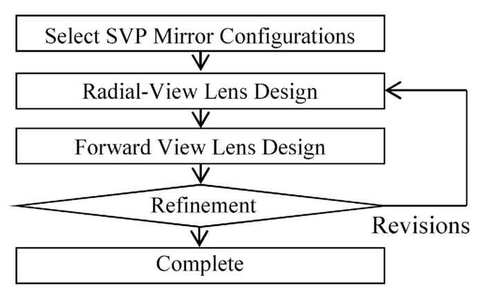
1.IntroductionFluorescence imaging has shown great potential to improve diagnosis for early detection of malignant lesions in the gastrointestinal (GI) tract. Endogenous tissue autofluorescence (AF) may provide physiological and biochemical information regarding the nature of the targeted biological system,1, 2, 3 while exogenous fluorescence has also been used to detect malignant lesions.4 In comparison to white light reflectance imaging, both endogenous and exogenous fluorescence signals are weak. The combination of white light endoscopy, AF imaging, and automated video processing could improve the screening sensitivity and specificity,5 as well as reduce the number of histopathology tests required.6 For screening applications with very low yields, capsule endoscopy is particularly attractive compared to traditional catheter-based endoscopes.7 There are several challenges to be met for practical in vivo AF imaging of the GI tract. First, high sensitivity photodetectors and efficient light collection optics are usually required to detect the weak AF signal.8 The AF signal is isotropic such that the irradiance on a detector decreases rapidly with the increase of the distance from the fluorophore. This implies the distance between the fluorophore and the collection optics should be minimized in AF imaging system designs. Second, in vivo endoscopic applications in a clinical setting require miniaturized components,9 which should fit inside the confined space of a GI endoscope sheath or endoscopic capsule. Despite advances in miniaturized optical10, 11 and high sensitivity photodetectors,8, 9, 12 these challenges still remain as obstacles to practical in vivo AF imaging of the GI tract. Most of the current wide-field endoscope objectives were built based on the Hopkins rod-lens design, which is capable of imaging a wide field-of-view (FOV) using small components.13, 14, 15 Wide FOV objectives are commonly used in standard video endoscopes.16 For example, a number of commercial wide-angle endoscope objective patents17, 18, 19, 20, 21 have similarities to the reversed telephoto lens form. In these wide-angle designs, the divergent lens group near the object is responsible for the large FOV. Aside from wide-field video endoscopy, many emerging scanning-based techniques have been developed for endoscopic applications. Some of these techniques include confocal,22 multiphoton,23, 24 endomicroscopy,25, 26 and optical coherence tomography.11 The intestine tends to contract around luminal objects,27 therefore the internal diameter of the GI tract can be practically assumed to be comparable to the diameter of the endoscope shaft during operation. Such lumen-occluding contractions generally bring the intestinal wall into close proximity with the endoscope shaft. It is very possible that involuntary GI movements for food transport and the collapse of the intestinal wall onto the endoscope would eventually orient the optical axis of the endoscope such that it is parallel to the direction of travel. This assumption does not hold for regions of the GI tract with larger local luminal space (e.g., the stomach), but these regions are relatively short compared to the total length of the GI tract. The object of interest in most GI endoscopy applications is the GI luminal wall. Due to the collapse of the GI tract on the cylindrical endoscope sheath, the lens-to-object distance would be minimized if the FOV of the endoscope is projected radially, as opposed to the forward direction. With a shorter lens-to-object distance, the numerical aperture (NA) for imaging the collapsed GI luminal wall surface could be optimized more efficiently than a forward-viewing endoscope. This could lead to a larger angle for the light collection cone. For a forward-viewing endoscope in Fig. 1a, the portion of GI luminal wall that is both in focus and within the FOV would depend on the depth-of-field (DOF) of the endoscope objective. Since the GI tract can practically be assumed to be collapsed onto the endoscope during operation, there is little variation in the radial lens-to-object distance. In the case of the radial-viewing endoscope in Fig. 1b, dependence on DOF is very limited due to the diameter of the GI luminal space being comparable to the endoscope sheath. Consequently, the light collected should be more uniform across the radial FOV, and the DOF design criteria of a radial-viewing endoscope could be relaxed. Fig. 1Comparisons of existing forward-viewing wide-angle endoscope objectives design (a), side-side view objective design (b), and an endoscope using a dual-view objective design (c). The proposed design encompasses only select components labeled in red in (c). The conventional forward-viewing wide-angle endoscopes have a wide FOV, but may not be efficient in imaging the off-axis luminal walls. Objects along the luminal wall would have different object depth distances for a forward-viewing endoscope. The diameter of the luminal space is approximately the same as the size of the endoscope sheath. This means the radial object depth distance in the side-viewing design (b) and (c) from the mirror is limited, and the amount of luminal wall imaged is less dependent on the DOF of the objective. The distance between the object and the light collection optics is also shorter. Lens 1 represents the lens group responsible to form an image from the radial FOV, and lens 2 represents the additional lens group required to form an image from the forward FOV. Mirror represents the mirror configuration used to redirect the radial FOV. The thick arrows indicate the coordinate position (6.9 and 3.7 mm) used in light collection simulation for the radial-viewing endoscopes, and the thin arrows (10 and 0 mm) serve a similar role for the forward-viewing endoscopes.  From the above discussion, radial-viewing endoscope objectives may be more suitable than forward-viewing objectives for applications that emphasize light collection. Panoramic image acquisition at the macroscale is a well-investigated area; some of the application-based literature include robotics,28 head-up displays,29 and surveillance.30 The method of panoramic acquisition was implemented by either catadioptric optics or foveated imaging techniques. Foveated imaging systems have variable magnification across its FOV.31, 32 The region of interest is usually assigned a higher magnification than other regions within the FOV. Catadioptric techniques utilize rotationally symmetric curved mirrors to redirect the FOV of a group of refractive elements.33, 34, 35 Due to the rotationally symmetric nature of the mirrors, the acquired panorama would appear circular. This acquired imagery may require further manipulation to reinterpret the scene objects in a more conventional perspective. Catadioptric panoramic imaging systems can be further classified as single-viewpoint (SVP) systems or nonsingle-viewpoint (nonSVP) systems. The SVP theory provided a well-conditioned initial design for the optimization scheme used in our design framework. The details of our proposed framework are explained in Sec. 2. The aforementioned panoramic imaging systems are typically used for imaging distances on the order of meters. Adopting the optical design for endoscopic applications was a nontrivial task. For example, the short lens-to-object distance in endoscopy applications imply significant aberrations and limited DOF. It is difficult to optimize a design subjected to such issues without reducing the NA, yet NA is one of the design criteria to be maximized. There had been reports of radial-viewing endoscope objective designs based on techniques from either foveated imaging36 or catadioptric optics.37 The report of the foveated objective design36 did not provide an in-depth analysis of their light uniformity. The catadioptric objective design37 utilized a folded mirror configuration. The center of the concave mirror was removed such that the light collection pathway would not be obstructed. The periphery of the concave mirror and the paraxial regions of the convex mirror were used to redirect the light collection pathway. This had the effect of minimizing the incident ray angles to the first refractive element. In essence, the refractive elements see the incoming rays as near paraxial, which allowed a simple doublet lens design to be used, while maintaining decent image quality. In this paper, we report an investigation on the design framework of a miniaturized endoscope objective. The target application is for GI screening. This design framework was used to generate a design simulation and a scaled-up prototype. The proposed design is capable of simultaneous acquisition of both the radial and forward views. Although light collection is important in endoscopic applications that involve weak optical signals, the presence of a forward-view is important for navigation and landmark recognition/co-registration purposes in practical GI endoscopy applications. Figure 1c illustrates how the proposed endoscope objective design could be used with other additional components to form a fully functional endoscope. The simplified mirror and lens groups are labeled with Mirror, Lens 1, and Lens 2. The paraxial region of the mirror group was removed so the light collection pathway for the forward-view was unobstructed. The peripheral regions of both mirrors were used to redirect the light collection pathway, which was a different optical design method than the surveyed catadioptric objective design.37 The presented work only covers the light collection module of an ongoing development project for an in vivo AF endoscope. The proposed objective design would eventually be coupled with an optimized illumination design and a hyperspectral photodetector. The emphasis on the proposed radial-view design was to maximize both the light collection and image quality. The emphasis on the forward-view was to provide a large enough FOV for navigation purposes. The proposed objective design assumed the imaging would occur in the visible spectrum, and the illumination implementation was assumed to be ultraviolet (UV) light-emitting diodes (LEDs). Some potential challenges for a radially projected excitation source include the small physical size limit and the low power consumption. The small physical size limit constraint will require the illumination pathway to partially utilize the optical components (e.g., the mirrors) from the light collection pathway. One possible method to reduce the power consumption is to use a pulsed illumination sequence (reduced duty cycle) that matches the imaging exposure time. The excitation pathway design and these two related issues will be addressed in a future paper. Although AF imaging was the original inspiration of this project, the dual-view design may also be applied to exogenous fluorescence imaging. This is because the collection of the exogenous fluorescence signal could also benefit from a similarly optimized objective. The intended use of the proposed dual-view endoscopic objective design is for capsule endoscopes. However, many of the challenges we encountered may be alleviated in catheter-based endoscopies (e.g., track length of the design). Therefore, our design framework shall not be limited only to capsule endoscopy. It may find some potential applications in specialized applications of catheter-based endoscopes. The proposed framework in this report could be re-optimized for a different set of operating wavelengths (e.g., other illumination schemes), and was validated using a 3:1 scaled-up prototype imaging system (Secs. 4, 5). 2.Design MethodsCommercial ray tracing packages were extensively used in our design framework. Sequential ray tracing with OSLOTM and ZEMAXTM were used for the lens design. Nonsequential ray tracing with LightToolsTM was used for the light collection simulations. The sequential ray tracing and nonsequential ray tracing application to the proposed framework are described in Secs. 2.3, 3.2, respectively. Sequential ray tracers are closely associated with lens design theory.38 The notion of chief rays, ray bundles, and aperture stops are central to the lens design theory. By definition, chief rays are required to pass through the center of the aperture stop of the optical system. Alternatively, the chief ray path may be interpreted as the unobstructed ray path that maps an object point with an image point, and the chief ray path must also intersect the center of the aperture stop.38, 39, 40 This description of the chief ray is related to the definition of a SVP constrained imaging system; an imaging system is said to be SVP constrained if the image formation rays are required to pass through a common point in space.33 The SVP theory ignores aberrations and diffraction effects. Each image formulation ray is the line-of-sight from an object point, with a direction toward the center of the entrance pupil as seen from the object point. This implies that an imaging system with a stationary entrance pupil would be a SVP constrained imaging system. SVP constrained mirror surfaces were used to provide an initial mirror design to the proposed design framework. In a typical sequential ray trace simulation, the rays interact with each of the specified optical surfaces in the order that they are defined. Although this simplifies the computation for the ray paths, the designer must ensure the placement of each optical surface is feasible. Illogical placement of optical surfaces would greatly decrease the feasible set of possible ray path solutions, and also decrease the chance of converging to a realistic ray path solution. The off-axis components in the radial-view may create ray convergence problems when using numerical solvers based on lens design theory (e.g., sequential ray tracers). We encountered convergence issues with the sequential ray tracer with a freeform design approach, but most SVP constrained initial design attempts were able to achieve convergence to a realistic ray path solution. Once an initial design solution was successfully simulated, the actual optimization for maximum light collection and image quality may be carried out. 2.1.Design FrameworkTraditional catadioptric optical designs (e.g., Cassegrain reflector) utilize the mirror to provide most of the focusing power, and the refractive elements were used for aberration control.38, 39, 40 In contrast, catadioptric panoramic designs utilize the mirrors for the redirection of the FOV of the refractive group of elements. Figure 2 illustrates a flowchart of our design framework. The SVP theory33 was used to identify potential mirror configurations. These potential mirror configurations were imported into separate sequential ray trace simulations to determine the FOV and NA. The most practical mirror configuration served as the initial mirror design for the subsequent design phases. The lens design phase began by the integration of the initial mirror design with a preselected lens template. Lens optimization was then performed iteratively until the radial-view design criteria were satisfied. The refractive elements in the radial-view were then imported into a new separate simulation, which was the forward-view simulation in the subsequent design phases. Additional refractive elements were inserted into the forward-view simulation, and described in Sec. 2.3.3 with more details. Lens optimization was then performed over these additional refractive elements. The most prioritized optimization criterion for the forward-view lens design was to match the back focus of its imaging plane to that of the radial-view design. This was a challenging task that required multiple readjustments of both the radial-view and forward-view lens design. The optimization process concluded when all specified criteria had been satisfied and manual refinement was carried out. After revising minor technical details that were not described in the optimization criteria, the design was deemed to be complete. The design criteria for the proposed design are summarized in Table 1. The image quality was evaluated using spot diagrams and modulation transfer functions (MTF). The targeted image detector is a hyperspectral CMOS device that is currently under development. The pixel pitch of this image detector was estimated to be approximately 5 × 5 μm. For efficient light collection onto one pixel, the upper bound of the root mean square (rms) spot size was set to 5 μm. This pixel pitch suggested a spatial sampling frequency of 100 lp/mm. From the Nyquist–Shannon sampling theorem, the analog optical signal should be roughly limited to spatial frequencies below 200 lp/mm to avoid aliasing. To determine the MTF cut-off, the minimum acceptable modulation score was taken to be 50% modulation. The image dimensions were taken from the surveyed endoscope objective patent designs17, 18, 19, 20, 21 for ease of comparison. The lower bound on the edge thickness was set to 0.6 mm, as per the recommendations from optical fabrication shops. The minimum radius of curvature and the image dimensions were set to be similar to that of the surveyed patents.17, 18, 19, 20, 21 FOV, DOF, and entrance pupil radius (EPR) were parameters in the optimization objective function to be maximized. Fig. 11The unprocessed images, (a) 0.5 lp/mm test pattern and (b) business card, are manipulated using precomputed mappings relationships to produce (c) and (d), respectively.  Table 1Design constraints for the proposed simulation design.
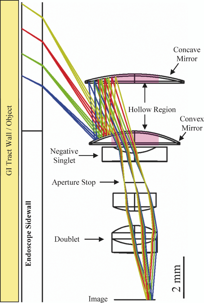
2.2.Mirror DesignTo determine a suitable initial mirror design, the expected FOV from various SVP constrained mirror surfaces were computed. From SVP theory, the solution to the family of single mirror surfaces that satisfy the SVP condition is as follows:33 Eq. 1[TeX:] \documentclass[12pt]{minimal}\begin{document}\begin{equation} \left({z - \frac{c}{2}} \right)^2 - r^2 \left({\frac{k}{2} - 1} \right) = \frac{{c^2 }}{4}\left({\frac{{k - 2}}{k}} \right)\,\,\left({k \ge 2} \right), \end{equation}\end{document}Eq. 2[TeX:] \documentclass[12pt]{minimal}\begin{document}\begin{equation} \left({z - \frac{c}{2}} \right)^2 + r^2 \left({1 + \frac{{c^2 }}{{2k}}} \right) = \left({\frac{{2k + c^2 }}{4}} \right)\,\,\left({k > 0} \right). \end{equation}\end{document}Folded mirror configurations were investigated, under the hypothesis that aberrations may be compensated if mirrors with opposite concavity are used. The coma and astigmatism aberrations introduced by the convex mirror were indeed reduced by the concave mirror. The folded mirror configurations shown in Fig. 3 were simulated using commercial sequential ray tracers. The ray angle incident on an optical surface has a significant impact on the resultant aberration; therefore, small tolerance deviations on the mirror curvature may induce significant aberration. Although the hyperbolic-ellipsoid configuration in Fig. 3a was a valid solution, the parabolic-parabolic configuration in Fig. 3b was chosen because the chief rays were practically parallel to each other in the region between the two mirrors. This phenomenon follows from the nature of a parabolic reflector; incident rays from different field angles that were aimed at the focus of a parabolic mirror would all be reflected in a parallel direction. This decoupled two mirrors: focus adjustments from one mirror would not require significant readjustments from the other mirror. This decoupling effect provided a more intuitive design flow, and increased the resilience of the design to tolerance-induced performance degradation. Fig. 3Ray trace layout with the aperture stop located at the focus of the convex mirror. The two candidate mirror configurations were: (a) convex hyperbolic and concave ellipsoidal mirrors, and (b) parabolic mirrors. The different colored ray bundles are from different object points within the FOV. The unit of the scale bar is millimeters, i.e., 1.86 mm in (a) and 2.27 mm in (b). 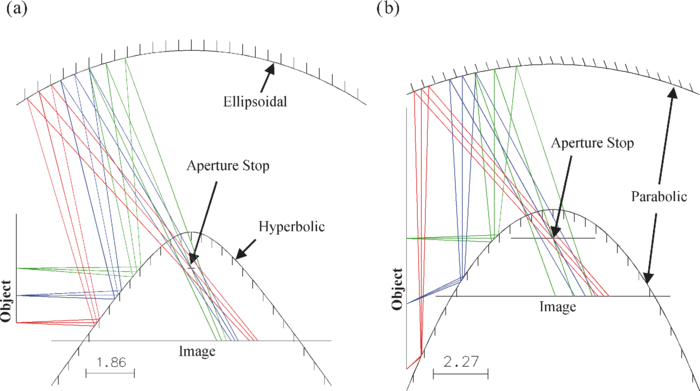 2.3.Lens Design2.3.1.Optimization considerationsThe paraxial regions of both mirrors were removed for the forward-view ray paths, and the peripheral regions of both mirrors were used for the radial-view ray paths. The cut-off radius of both mirrors was optimized for maximum radial FOV without significant vignetting of the blue and yellow ray bundles near the edge of the FOV in Fig. 4. With reference to Fig. 4, the blue ray bundle is the lowest bundle from the object, and the yellow ray bundle is the highest bundle from the object. The blue bundle is imaged furthest away from the optical axis, and the yellow bundle is imaged closest to the optical axis. To maximize the amount of area used on the image detector, additional optimization constraints were set on the image heights of selected field points across the FOV. The wavelengths 486.1, 587.6, and 656.3 nm had been used with equal weights for the lens optimization routines. It was assumed that UV LEDs would be used as the excitation source for radial-view AF imaging, and white light LEDs would be used for the radial-view and forward-view white light imaging. In a fully functional florescence imaging system, the UV and the shorter wavelengths of the visible spectrum would be attenuated by other filter components, thus they were not considered in the lens design. 2.3.2.Radial-view lens design processSimilar to the design of most current optical system design processes,38, 39, 40 the radial-view lens design started with an existing lens template design. This template was chosen from the surveyed wide-angle endoscope objective patent designs,17, 18, 19, 20, 21 and the chosen design template had a practical balance between short track length, large FOV, and mild radius of curvature (ease of manufacturability). Wide FOV was required to image the periphery of the concave mirror, which was responsible for providing the ray path for the radial-view. Lens designs of this scale with severe radius of curvatures would have high manufacturing complexity and cost. To avoid stress-induced ischemia on the GI tissue,41 the optical components used for endoscope objectives should be smaller than the diameter of the GI tract. The chosen patent design21 had mild radii of curvature for all its lens components, effective focal length (EFL) of ∼1 mm, track length of ∼9.9 mm, and hyperfocal distance of ∼4.3 mm. After the lens template was integrated with the mirror simulation, some negative elements were removed to increase the EPR. The field flattener lens near the imaging plane in the template lens design was removed to improve the DOF, and to allow practical matching of the back focus between the two views. The final radial-view lens design consisted of a negative lens in front of a Kellner eyepiece, as illustrated in Fig. 4. The singlet negative lens in Fig. 4 contributed to the correction of field curvature aberrations, and it controlled the back focus distance by reducing the optical power of the system. One method of correcting field curvature without the use of a field flattener is to use a strong negative lens with a low incident ray height to avoid significant increase of the overall focal length; this was used in the design philosophy of the Cooke Triplet.38, 39, 40 The marginal ray height on the negative singlet lens in Fig. 4 was no longer near the paraxial region, thus, the EFL was slightly increased (+0.2 mm). This increase in EFL led to the decrease in total optical power, but the light collection was also reduced. However, the longer EFL helped to increase the back focus of the radial-view optics, such that practical matching of the back focus with the back focus of the forward-view optics was made possible. The lenses below the aperture stop in Fig. 4 constitute a Kellner eyepiece lens form. Eyepiece lens forms are usually suitable for low FOV applications. The marginal ray angle incident on the eyepiece was 15 deg, which was a modest angle of incidence compared to 63 deg for the singlet negative lens. The front convex surfaces were used to correct coma aberrations, while the break in the refractive index in the doublet was used to correct field curvature and astigmatism aberrations.38 2.3.3.Forward-view lens design processThe lenses responsible for the forward-view light path are shown in Fig. 5. They include the radial-view lenses and additional lenses placed in front of the mirrors. These additional lenses are referred to as the forward-view lens group. One challenge for the forward-view lens design was the matching of the radial-view and forward-view back focuses. Another challenge was the design of a wide FOV for the forward view with a fixed field stop aperture size. The forward-view field stop was the central opening of the parabolic mirrors, and a change in its diameter would compromise the radial FOV. The lens system in Fig. 5 resembled a reverse telephoto lens form, where the first Zeonex™ plastics lens acted as the optical dome of the endoscope. The first two lenses compressed the field rays to implement a moderate FOV. The third lens helped to correct the field curvature. The fourth element had an aspherical front surface that corrected other primary aberrations, and a back surface that controlled the back focus. 3.Simulation Results3.1.Design EvaluationThe simulated performance comparison between the proposed design and the reference forward-viewing design is summarized in Table 2. The reference design was taken to be the patent design21 that was used as the starting lens template for the radial-view lenses. The proposed radial-view design had larger NA in the object space and EPR. The largest rms spot sizes were ∼4.0 and ∼1.9 μm for the radial and forward views, respectively. This was beneficial to light collection since most of the rays from the object would be concentrated on an area smaller than the specified pixel pitch of 5 μm in Table 1. The spot diagram in Fig. 6a for the forward-view design did not have similar spot sizes for each of the three color-coded design wavelengths. This indicates a chromatic shift in the focus position. The spot sizes across the different wavelengths were similar for the radial-view optics, as shown in the spot diagram in Fig. 6b. Fig. 6Image surface spot diagram for (a) forward-view optics and (b) radial-view optics. The black circle is the simulated Airy Disk radius. The colors correspond to the wavelength legend at the top right of this figure; all units are in micrometers. RMS radius is the root mean square spot size, and GEO radius is the distance from the centroid to the furthest ray intersection with the imaging surface. IMA describes the location of the centroid on the imaging surface. OBJ describes the location of the field points in terms of field angles. The forward optics has smaller spot sizes than the sidewall optics. 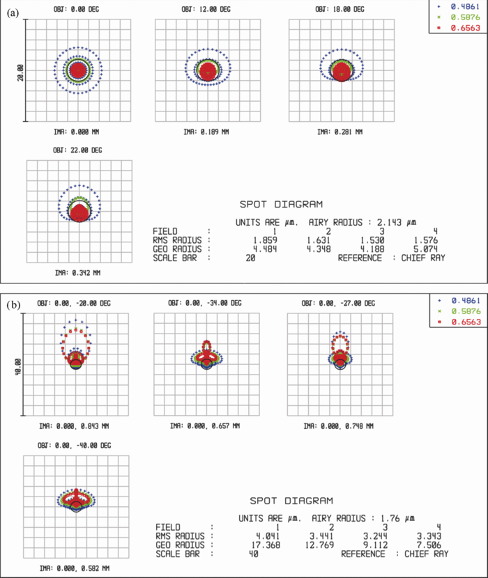 Table 2Simulation results: comparison of the template lens patent with the proposed system.
The simulated MTF was calculated from the modulus of the optical transfer function by the commercial sequential ray tracer. It can be seen from Fig. 7a that the simulated nominal modulation for the forward-view design dropped below 50% at spatial frequencies higher than 160 lp/mm. In Fig. 7b, the simulated nominal modulation for the radial-view design dropped below 50% at spatial frequencies higher than 120 lp/mm. These nominal simulated MTF scores were below the upper bound specified in Table 1, so aliasing should not occur. Due to the presence of fabrication and alignment tolerances,39 the actual performance of a lens design is expected to be lower. As evident from the similar spot diagrams across the design wavelengths, chromatic aberration was not a significant problem for the radial-view design. Fig. 7Simulated MTF for (a) forward-view optics and (b) radial-view optics. T is tangential MTF curve at the specified field point. S is sagittal MTF curve at the specified field point. Field points are specified in terms of field angle (measured in degrees). DIFF. LIMIT is the theoretical diffraction limited MTF curve. 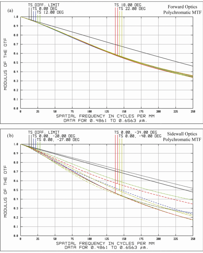 3.2.Irradiance SimulationCommercial illumination optical design packages are adept at the computation of radiometric quantities at specified detector surfaces. These packages often employ nonsequential ray tracing algorithms that generate a high number of rays that are not required to pass through the specified optical surfaces in sequential order (e.g., no pre-defined ray path). In exchange for computational time, this type of ray tracing allows stray light contributions to the irradiance on the image detector to be accounted for. Light intensity contributions from stray light incident on the image detector could be considered as noise, and could contribute to form ghost images.39 The LightToolsTM commercial illumination design package is based on nonsequential ray tracing, and it was used in this work to provide a relative irradiance collection comparison between the designs. The endoscope sheath material was a poly(methylmethacrylate) (PMMA) tube with a thickness of 1 mm. Another set of simulations were performed for the proposed design without the endoscope sheath. This was to compare the effect when different sheath materials were used. The light reflected or emitted (such as in the case of AF imaging) from the collapsed GI wall were modeled using point sources placed across the FOV of the radial-view design. Due to the different FOV orientation of the proposed radial-view design and forward-viewing reference design, the source locations for both simulations had to be different. In Fig. 1c, the locations of the simulation field points are marked for the radial-view design and the reference design. The cylindrical endoscope sheath had an outer radius of 5.5 mm, and the linear FOV projected onto this surface was 3.76 to 6.9 mm (Table 3). This corresponded to an imaging length of 3.14 mm along the cylindrical surface. The point sources were set to have 100 W evenly distributed over its entire projection sphere. The large power distribution of 100 W was chosen to avoid the computation of extremely small numbers, therefore, this measure of light collection served only as a relative comparison. The irradiance plot in Fig. 8 was computed using samples at the surface of the image detector. Each bin was set to 95 × 95 μm for practical computation, and to increase the signal-to-noise ratio. Table 3Radiometry simulation results.
4.Prototype DevelopmentTo validate the proposed design framework within a reasonable budget, a 3:1 scaled-up prototype of the proposed design was developed with modified design criteria. Only the image quality was validated in this report. The illumination design is an investigation in progress and thus empirical radiometry experiments are not included here. In addition, a proof-of-concept panoramic image rectification algorithm was investigated. C-mount mechanical threading was used to interface between the lens barrel and a commercial CMOS camera (Mightex Systems, MCE-B013-U). The fabrication of customized optical and optomechanical components as well as system assembly was contracted to the Instrument Technology Research Center of the National Applied Research Laboratories (ITRC-NARL, Hsinchu, Taiwan). 4.1.Prototype Design SpecificationThere were three new design considerations for the prototype; 1. to achieve convenient manufacturability, 2. to provide integration with a commercial CMOS camera, and 3. similarity to the proposed simulation design described in Sec. 3. Table 4 summarizes the evaluation and fabrication specifications used for the prototype design. The CMOS camera had an image dimension of 6.66 mm × 5.32 mm, which was different from the image dimension of 2 mm × 2 mm used in the proposed simulation design. Constraints were added such that the design rays would approximately sample the radial-view FOV in a uniform manner. The camera has a pixel pitch of 5.2 μm, which defined the upper bound of the rms spot size. The lower bound on the MTF with tolerance considerations was set to 30 lp/mm, which was approximately one-third of the nominal MTF lower bound for the proposed simulation design in Table 1. The nominal MTF calculation was used during the lens optimization because tolerance simulations are time consuming. The lower bound of the nominal MTF simulation score in Table 4 (60 lp/mm) was set to significantly exceed the tolerance MTF score to compensate for the anticipated performance drop from manufacturing and assembly tolerance. Other fabrication related specifications in Table 4 were based on recommendations from the ITRC-NARL. The additional specifications for the prototype cannot be satisfied with a mere scaled version of the simulation design from Sec. 3. Nevertheless, minor modifications in the optimization constraints yielded a suitable initial prototype prescription. After an initial round of optimization, each lens prescription was compared with stock lenses across different catalogues. Several stock lenses were found to be similar to particular lens prescriptions. Certain elements in the design were functionally separable, such that multiple elements with similar stock prescriptions was be used in its place. After the selected stock lenses were incorporated into the design, the optimization process was iterated to compensate the aberration induced by the stock lenses. This iterative process lasted until the optimization constraints were met. Table 4Design constraints for the prototype simulation design.
4.2.Tolerance SimulationThe tolerance simulation was conducted via the commercial optical design packages, ZEMAXTM and OSLOTM. The built-in Monte Carlo tolerance simulation was used to take tolerance deviations into account. Fifty design simulations were generated from random perturbation of each optical surface in the nominal design. These perturbations have a maximum magnitude specified by the tolerance input. Their probability distribution was set to be parabolic, in which the maximum extremes of the permissible perturbation were more likely to occur. The specified MTF criterion (30 lp/mm at 50% modulation for radial-view) was simulated for each of the 50 perturbed designs, then the statistics of these simulations were computed. This tolerance simulation provided a probability of the performance one may expect from a manufactured system with the specified tolerance. 5.Prototype Results5.1.Prototype EvaluationThe assembled prototype in Fig. 9 consisted of a lens barrel housing for all the optical components. The assembled prototype was 7.6 cm long and 2.8 cm in diameter. The simulated prototype performance is shown in Table 5. The track length of the prototype prescription was ∼83 mm, and the radial FOV was ∼23°. Figure 10a is the acquired image used for the forward-view MTF test. The USAF1951 target (Thorlabs R3L3S1N) was backlit, and it was placed 2 cm from the front lens surface of the lens barrel. The resolutions of the test patterns in Fig. 10a are listed in Table 6. The top-left horizontal bar pattern is group 0 and element 2, which corresponded to a spatial frequency of 1.12 lp/mm from the USAF1951 specification. The maximum frequency measured for the forward-view was 5.66 lp/mm on the object side, where the modulation was slightly over 50%. After multiplying by a forward view magnification factor of 16.3 (Table 5), this corresponded to a resolution of 92 lp/mm on the image side. The radial-view FOV was not illuminated in Fig. 10a and appeared dark. Figure 10b is the acquired image of a 2 lp/mm pattern. The radial FOV corresponds to the annular region indicated by the double-ended arrows. The forward FOV is the central circular region of the image, and the paper outline of the cylindrical test pattern could be seen near the center of the image. The fixed frequency pattern was rolled into a cylindrical tube [Fig. 10c], and placed around the prototype. The cylindrical test pattern had different line pair orientations for the tangential and sagittal radial contrast measurements. The prototype was then placed in the center of the test pattern tube to acquire the radial-view contrast modulation [Fig. 10d]. Similar fixed frequency test patterns were used to calculate the radial-view contrast modulation in Table 7, whereas the forward-view used the USAF1951 target. Table 7 shows the comparison between the simulated MTF performance after accounting for tolerance and the measured contrast modulation scores. Fig. 9Photograph of the 3:1 scale prototype. Four pillars are used to connect the front and back optics groups instead of using transparent housing. The entire device is 7 cm long and 3 cm in diameter. 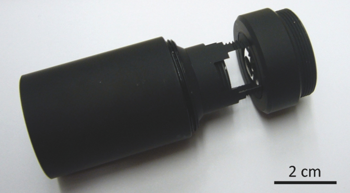 Fig. 10Acquired images and the radial-view image acquisition setups. The forward-view acquisition (a) used the USAF1951 target as the test pattern. The four pillars in the radial-view acquisition (b) are part of the housing for the prototype, and the annular region spanned by the double-ended arrows is the radial-view FOV. The scene in (b) was constructed from a custom printed and fixed frequency (2 lp/mm) pattern (c), which was rolled into a tube with a sagittal oscillation direction. This test pattern tube was then fixed around the prototype to create a cylindrical scene, as shown in (d). 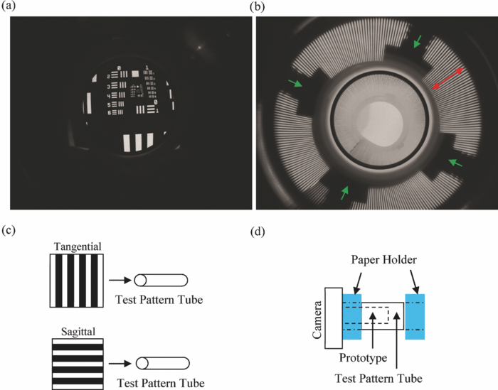 Table 5Simulation results: prototype design.
Table 6Number of line pairs/millimeter in the USAF 1951 test chart.
Table 7Comparison of measured MTF and tolerance simulated average MTF.
5.2.Image Post-ProcessingThe target application of the proposed imaging system is the diagnostic screening of the GI tract, in which case the gastroenterologist would need to interpret the acquired imagery. Although automated post-processing of the acquired endoscope video may be able to identify potentially malignant regions, a certified diagnosis would require a gastroenterologist to interpret the video frames. The use of curved mirrors had induced distortion on the acquired imagery. This may cause some inconvenience for a human to interpret of the radial-view imagery. There are existing publications42, 43 that describe rectification algorithms for panoramic images that were acquired from catadioptric optical devices. Most of these algorithms are based on the pinhole camera model, which is a popular paradigm in the fields of computational vision and computer graphics. In this work, we propose an alternative method for scene reinterpretation. If successful, a sequential ray trace simulation would establish a mapping between the sampled object points to corresponding blur regions on the image detector. These blur regions are characterized by the point-spread function of the imaging system. This mapping relationship could be simplified by collapsing the blur area on the image to its rms centroid. For an imaging system with a radial FOV, the notion of object depth corresponds to the radial distance between the object and the imaging system. Our method for scene reinterpretation is based the use of precomputed object-image point mappings as a look-up-table. Due to the limited radial DOF range in GI endoscopic applications, it was feasible for us to build a database of the ray traced results of sampled object points. These object points were sampled across the FOV and the DOF of the nominal prototype design simulation. Cubic spline interpolation algorithms were used to interpolate values between the entries of the database. This database was used to process two acquired images for proof-of-concept purposes. The two acquired images in Figs. 11a and 11b were processed by this implementation of the ray database to generate Figs. 11c and 11d. Figure 11a is the radial-view test pattern at 0.5 lp/mm, and Fig. 11b is a business card wrapped around the prototype. The object points were sampled across 10 different object depths within the DOF and 36 samples were taken across the FOV. 6.Discussion6.1.PerformanceLow chromatic aberration in the design was desired, because the emission spectrum of tissue AF due to UV excitation is broadband. The forward-view was designed only to provide white light imaging for navigation purposes, hence the noticeable chromatic focus shift in Fig. 6a was deemed acceptable. The proposed radial-view design achieved similar spot sizes across the three design wavelengths (486.1, 587.6, and 656.3 nm) in Fig. 6b. The forward-view nominal MTF in Fig. 7a was lower than the aliasing upper bound specified in Table 1. Both the tangential and saggital nominal MTF were similar. This was not true for the nominal MTF for the radial-view in Fig. 7b, and extra weights may need to be assigned to equalizing the MTF in both directions for future work. The irradiance chart in Fig. 8 is similar to a spot diagram, but with very coarse sampling. The ability to simulate the amount of irradiance on a pixel could be induced in the optimization framework for future work. In Table 3, the irradiance collection of the proposed design in the radial-view was much more uniform across its FOV than the reference forward-viewing design. The reference design had better light collection efficiency at objects closer than 3 mm. For objects further than 3 mm, the light collection ability diminished quickly. For object distances shorter than the DOF, Table 2 shows that the rms spot size of the reference design was larger than 10 μm. This suggests more light was collected for objects near the reference design, but at the expense of reduced image quality. The exclusion of a PMMA endoscope sheath gave interesting results; closer objects experienced a decrease in light collection, and distant objects experienced an increase in light collection, relative to the proposed design with a PMMA sheath. The field angle distribution was altered when the endoscope sheath material was changed to air, which led to a modified entrance pupil size. The difference in light collection between sheathed and sheathless designs was small (Table 3). Different endoscope sheath materials may be used with minor impact on the overall light collection characteristics. In depth revision of the imaging system with different sheath materials could be performed by running the lens optimization in most commercial optical design packages. 6.2.Design Robustness and IssuesMonte Carlo tolerance simulations were conducted using commercial optical design packages. The statistics were set to have larger probability at the endpoints of the tolerance interval. In other words, the perturbations of optical elements during manufacturing were assumed to be more probable at the extremes of the allowed tolerance. This is a stringent assumption that may be relaxed in future simulations. The measured forward-view MTF performance of the fabricated prototype (Table 7) was in fact higher than expected (Table 4). The measured radial-view MTF in the tangential and sagittal directions were dissimilar in Table 7, but the averaged MTF score between the two directions was within the expected range. This was because the averaged MTF was used as the evaluation criterion for the tolerance simulations. For future work, additional constraints should be placed on both the MTF directions during optimization. The concave mirror in the proposed design could not have a shorter focal length than the distance between the folded mirrors. This was due to practical optomechanical stability issues on the negative singlet lens in Fig. 4. Therefore, the design was re-optimized such that the radial-view lens group contributed a moderate amount of optical power to the system. The mirrors provided the remaining optical power, as well as the redirection of the FOV of the radial-view lens group. The radius of curvature of the doublet in Fig. 4 was the shortest in the entire design (∼1.8 mm). Attempts in splitting the power of the doublet proved to be unsuccessful, since it was instrumental in the correction of coma aberration. The clear aperture of that doublet may need to be smaller, e.g., 10% smaller, to satisfy the minimum edge thickness specified for some lens manufacturing processes. If the clear aperture were to decrease, the ray bundles that are far from the optical axis in Fig. 4 would suffer from vignetting effects. This would reduce the light collection of the field points near the edge of the FOV. The nonreflecting portions of the mirrors in the manufactured prototype were treated with black micro-arc oxidation to reduce stray light. The four pillars indicated by the single-ended arrows in Fig. 10b are the pillars that hold the two mirrors together in Fig. 9. In the simulation design, there were no pillars and the space between the mirrors would be supported by a transparent cylindrical sheath. As the illumination design was not addressed by this work, backlit illumination was used for both Figs. 10a and 10b. 6.3.Application IssuesThe diameter and track length of typical capsule endoscopes range between 9 to 11 mm and 12 to 26 mm, respectively.44, 45 The maximum track length of capsule endoscope optics should be less than 15 mm in order to have room for other components, e.g., antennas and batteries.9 From Table 2, the simulated track length of the proposed design was 19.5 mm, which is twice as long as the reference design.21 The proposed design was not scaled down further, because a design with shorter radii of curvature is unlikely to be technically or economically feasible with present day lens manufacturing processes. Although the simulated track length of the current design was 19.5 mm (Table 2), it should be suitable for catheter-based devices. One alternative application of the proposed design could be the imaging of colon polyps, which are usually hidden behind folds of the colon. The radial imagery would require post-processing to generate an interpretable view of the scene. The results of a proof-of-concept algorithm are shown in Figs. 11c and 11d, where the acquired radial panorama imagery was manipulated to appear more user-friendly. Although the FOV between the forward and the radial view is discontinuous, it may be possible to estimate a mosaic map in a post-processing of the acquired video.45, 46, 47 7.Conclusion and Future WorkWe have designed and characterized a dual-view (forward and radial) catadioptric optical system for minimally invasive endoscopic screening of GI disease. The dual-view optical design allows the simultaneous acquisition of both the radial-view (imaged as an annular region) and the forward-view (imaged as a circular region). A number of optical simulation packages such as OSLOTM, ZEMAXTM, and LightToolsTM were used to complement each other throughout this design process. We have also documented our design framework, which others may use to design similar endoscope systems. Although the current project was intended for AF imaging in a capsule endoscope, the design may also be applied in other endoscopic imaging modalities where the optical signal is weak, e.g., exogenous fluorescence imaging and narrow band imaging. The detailed design analysis of the illumination and AF excitation pathway is an ongoing investigation, and will be reported in the future. Radiance matching between the illumination source, the object, and then the proposed design, is projected to be a crucial topic of our illumination design investigation. Different algorithms for reinterpreting the acquired radial panorama image will also be investigated. AcknowledgmentsThe authors would like to express gratitude to the Instrument Technology Research Center (ITRC) of the National Applied Research Laboratories (Hsinchu, Taiwan) in providing a significant academic discount on the fabrication of the prototype. Dr. Donyau Chiang, Mr. Cheng-Fong Ho, Mr. Zong-Ru Yu, and others from the ITRC team provided many valuable technical inputs during the final prototype revisions. This project is supported in part by funding from the Natural Sciences & Engineering Research Council (NSERC) of Canada and Ontario Ministry of Research and Innovation. M.J.D. acknowledge sponsorship of visiting professorship from KOSEF-MEST (No. R31–2008-000–10100-0). ReferencesG. W. Falk,
“Autofluorescence endoscopy,”
Gastro. Endo. Clin. N. A., 19
(2), 209
–220
(2009). https://doi.org/10.1016/j.giec.2009.02.004 Google Scholar
M. A. Kara, F. P. Peters, P. Fockens, F. J. W. ten Kate, and
J. J. G. H. M. Bergman,
“Endoscopic video-autofluorescence imaging followed by narrow band imaging for detecting early neoplasia in Barrett's esophagus,”
Gastro. Endo., 64
(2), 176
–185
(2006). https://doi.org/10.1016/j.gie.2005.11.050 Google Scholar
M. Goetz and
T. D. Wang,
“Molecular imaging in gastrointestinal endoscopy,”
Gastroenterology, 138
(3), 828
–833
(2010). https://doi.org/10.1053/j.gastro.2010.01.009 Google Scholar
E. Dekker and
P. Fockens,
“New imaging techniques at colonoscopy: tissue spectroscopy and narrow band imaging,”
Gastro. Endo. Clin. N. A., 15
(4), 703
–714
(2005). https://doi.org/10.1016/j.giec.2005.08.006 Google Scholar
W. L. Curvers, F. G. van Vilsteren, L. C. Bakk, C. Böhmer, R. C. Mallant-Hent, A. H. Naber, A. van Oijen, C. Y. Ponsioen, P. Scholten, E. Schenk, E. Schoon, C. A. Seldenrijk, G. A. Meijer, F. J. W. ten Kate, and
J. J. G. H. M. Bergman,
“Endoscopic trimodal imaging versus standard video endoscopy for detection of early Barrett's neoplasia: a multicenter, randomized, crossover study in general practice,”
Gastro. Endo., 73
(2), 195
–203
(2011). https://doi.org/10.1016/j.gie.2010.10.014 Google Scholar
A. C. de Vries, J. Haringsma, R. A. de Vries, F. Ter Borg, N. C. van Grieken, G. A. Meijer, H. van Dekken, and
E. J. Kuipers,
“Biopsy strategies for endoscopic surveillance of pre-malignant gastric lesions,”
Helicobacter, 15
(4), 259
–264
(2010). https://doi.org/10.1111/j.1523-5378.2010.00760.x Google Scholar
A. K. Hara, J. A. Leighton, R. I. Heigh, V. K. Sharma, A. C. Silva, G. de Petris, J. G. Hentz, and
D. E. Fleischer,
“Crohn disease of the small bowel: preliminary comparison among CT enterography, capsule endoscopy, small-bowel follow-through, and ileoscopy,”
Radiology, 238
(1), 128
–134
(2006). Google Scholar
N. Faramarzpour, M. J. Deen, S. Shirani, Q. Fang, L. W.–C. Liu, F. de Souza Campos, and
J. W. Jacobus,
“CMOS-based active pixel for low-light-level detection: analysis and measurements,”
IEEE Trans. Electron Devices, 54
(12), 3229
–3237
(2007). https://doi.org/10.1109/TED.2007.908594 Google Scholar
K. Moussa, O. Marinov, P. Quevedo, N. Faramarzpour, S. Shirani, L. W. –C. Liu, Q. Fang, and
M. J. Deen,
“Toward a miniaturized wireless fluorescence-based diagnostic imaging system,”
IEEE J. Sel. Top. Quantum Electron., 14
(1), 226
–234
(2008). Google Scholar
R. T. Kester, T. Christenson, R. R. Kortum, and
T. S. Tkaczyk,
“Low cost, high performance, self-aligning miniature optical systems,”
Appl. Opt., 48
(18), 3375
–3384
(2009). https://doi.org/10.1364/AO.48.003375 Google Scholar
H. L. Fu, Y. Leng, M. J. Cobb, K. Hsu, J. H. Hwang, and
X. Li,
“Flexible miniature compound lens design for high-resolution optical coherence tomography balloon imaging catheter,”
J. Biomed. Opt., 13
(6), 060502
(2008). https://doi.org/10.1117/1.3037340 Google Scholar
M. El-Desouki, M. Jamal Deen, Q. Fang, L. Liu, F. Tse, and
D. Armstrong,
“CMOS image sensors for high speed applications,”
Sensor, 9
(1), 430
–444
(2009). https://doi.org/10.3390/s90100430 Google Scholar
G. Berci, Endoscopy, Appleton-Century-Crofts, New York
(1976). Google Scholar
W. S. Cockett and
A. T. Cockett,
“The Hopkins rod-lens system and the Storz cold light illumination system,”
Urology, 51
(5), 1
–2
(1998). https://doi.org/10.1016/S0090-4295(98)00060-0 Google Scholar
G. J. Fuchs,
“Milestones in endoscope design for minimally invasive urologic surgery: the sentinel role of a pioneer,”
Surg. Endosc., 20
(2), S493
–S499
(2006). https://doi.org/10.1007/s00464-006-0078-4 Google Scholar
V. L. Fox,
“Pediatric endoscopy,”
Gastroenterological Endoscopy, 765
–784 Thieme, Stuttgart
(2010). Google Scholar
T. Uzawa, K. Kasai, and
T. Kato,
“Object lens and endoscope using it,”
(2006). Google Scholar
S. Saito,
“Objective lens for endoscope,”
695,670,318
(2005). Google Scholar
H. Miyano,
“Endoscope objective lens,”
721,845,415
(2007). Google Scholar
H. Miyano,
“Four-group endoscope objective lens,”
(2006). Google Scholar
H. Miyano,
“Objective lens for endoscope, and imaging apparatus for endoscope using the same,”
(2009). Google Scholar
“Confocal laser endoscopy for diagnosing intraepithelial neoplasias and colorectal cancer in vivo,”
Gastroenterology, 127
(3), 706
–713
(2004). https://doi.org/10.1053/j.gastro.2004.06.050 Google Scholar
M. T. Myaing, D. J. MacDonald, and
X. Li,
“Fiber-optic scanning two-photon fluorescence endoscope,”
Opt. Lett., 31
(8), 1076
–1078
(2006). https://doi.org/10.1364/OL.31.001076 Google Scholar
J. C. Jung and
M. J. Schnitzer,
“Multiphoton endoscopy,”
Opt. Lett., 28
(11), 902
–904
(2003). https://doi.org/10.1364/OL.28.000902 Google Scholar
S. Foersch, R. Kiesslich, M. J. Waldner, P. Delaney, P. R. Galle, M. F. Neurath, and
M. Goetz,
“Molecular imaging of VEGF in gastrointestinal cancer in vivo using confocal laser endomicroscopy,”
Gut., 59 1046
–1055
(2010). https://doi.org/10.1136/gut.2009.202986 Google Scholar
Y. Wu, J. Xi, M. J. Cobb, and
X. Li,
“Scanning fiber-optic nonlinear endomicroscopy with miniature aspherical compound lens and multimode fiber collector,”
Opt. Lett., 34 953
–955
(2009). https://doi.org/10.1364/OL.34.000953 Google Scholar
S. R. Paulsen, J. E. Huprich, J. G. Fletcher, F. Booya, B. M. Young, J. L. Fidler, C. D. Johnson, J. M. Barlow,
“CT enterography as a diagnostic tool in evaluating small bowel disorders: review of clinical experience with over 700 cases,”
Radiographics, 26
(3), 641
–657
(2006). https://doi.org/10.1148/rg.263055162 Google Scholar
G. L. Mariottini and
D. Prattichizzo,
“Image-based visual servoing with central catadioptric cameras,”
Int. J. Robot. Res., 27
(1), 41
–56
(2008). https://doi.org/10.1177/0278364907084320 Google Scholar
M. Haller, M. Billinghurst, and
B. H. Thomas, Emerging Technologies of Augmented Reality: Interfaces and Design, Idea Group Inc., Hershey, Pennsylvania
(2007). Google Scholar
C. Gimkiewicz, C. Urban, E. Innerhofer, P. Ferrat, S. Neukom, G. Vanstraelen, and
P. Seitz,
“Ultra-miniature catadioptrical system for an omnidirectional camera,”
Proc. SPIE, 6992 69920J
(2008). Google Scholar
H. Hua and
S. Liu,
“Dual-sensor foveated imaging system,”
Appl. Opt., 47
(3), 317
–327
(2008). https://doi.org/10.1364/AO.47.000317 Google Scholar
G. Curatu and
J. E. Harvey,
“Analysis and design of wide-angle foveated optical systems based on transmissive liquid crystal spatial light modulators,”
Opt. Eng., 48
(4), 043001
(2009). https://doi.org/10.1117/1.3122006 Google Scholar
S. Baker and
S. K. Nayar,
“A theory of single-viewpoint catadioptric image formation,”
Int. J. Comput. Vis., 35 175
–196
(1999). https://doi.org/10.1023/A:1008128724364 Google Scholar
R. A. Hicks and
R. K. Perline,
“Equiresolution catadioptric sensors,”
Appl. Opt., 44
(29), 6108
–6114
(2005). https://doi.org/10.1364/AO.44.006108 Google Scholar
G. Kweon, K. T. Kim, G. Kim, and
H. Kim,
“Folded catadioptric panoramic lens with an equidistance projection scheme,”
Appl.Opt., 44
(14), 2759
–2767
(2005). https://doi.org/10.1364/AO.44.002759 Google Scholar
P. Roulet, P. Konen, M. Villegas, S. Thibault, and
P. Y. Garneau,
“360° endoscopy using panomorph lens technology,”
Proc. SPIE, 7558 75580T
(2010). https://doi.org/10.1117/12.842417 Google Scholar
W. Smith, Modern Lens Design, McGraw-Hill Professional, New York
(2004). Google Scholar
R. E. Fischer, B. Tadic-Galeb, and
P. R. Yoder, Optical System Design, McGraw-Hill Professional, New York
(2008). Google Scholar
W. Smith, Modern Optical Engineering, McGraw-Hill Professional, New York
(2007). Google Scholar
H. D. Høeg, A. B. Slatkin, J. W. Burdick, D. W. S. Grundfest, D. Warren, and
S. Grundfest,
“Biomechanical modeling of the small intestine as required for the design and operation of a robotic endoscope,”
1599
–1606
(2000). Google Scholar
M. Magnor, Video-Based Rendering, AK Peters, Wellesley, Massachusetts
(2005). Google Scholar
H. P. Wu, M. Lee, P. Weng, and
S. Chen,
“Epipolar geometry of catadioptric stereo systems with planar mirrors,”
Image Vis. Comput., 27
(8), 1047
–1061
(2009). https://doi.org/10.1016/j.imavis.2008.09.007 Google Scholar
M. Simi, P. Valdastri, C. Quaglia, A. Menciassi, and
P. Dario,
“Design, fabrication, and testing of a capsule with hybrid locomotion for gastrointestinal tract exploration,”
IEEE/ASME Trans. Mecha., 15
(2), 170
–180
(2010). https://doi.org/10.1109/TMECH.2010.2041244 Google Scholar
E. J. Seibel, R. E. Carroll, J. A. Dominitz, R. S. Johnston, C. D. Melville, C. M. Lee, S. M. Seitz, and
M. B. Kimmey,
“Tethered capsule endoscopy, a low-cost and high-performance alternative technology for the screening of esophageal cancer and Barrett's esophagus,”
IEEE Trans. Biomed. Eng., 55
(3), 1032
–1042
(2008). https://doi.org/10.1109/TBME.2008.915680 Google Scholar
V. Becker, T. Vercauteren, C. H. von Weyhern, C. Prinz, R. M. Schmid, and
A. Meining,
“High-resolution miniprobe-based confocal microscopy in combination with video mosaicing (with video),”
Gastro. Endo., 66
(5), 1001
–1007
(2007). https://doi.org/10.1016/j.gie.2007.04.015 Google Scholar
A. Behrens, M. Bommes, T. Stehle, S. Gross, S. Leonhardt, and
T. Aach,
“Real-time image composition of bladder mosaics in fluorescence endoscopy,”
Comp. Sci. – Res. Devp., 26
(1–2), 51
–64
(2010). Google Scholar
|
||||||||||||||||||||||||||||||||||||||||||||||||||||||||||||||||||||||||||||||||||||||||||||||||||||||||||||||||||||||||||||||||||||||||||||||||||||||||||||||||||||||||||||||||||||||||||||||||||||||||||||||||||||||||||||||||||||||||||||||||||||||||||||||||||||||||||||||||||||||||||||||||||