|
|
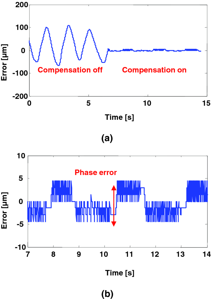
1.IntroductionMicrosurgery requires constant attention to and compensation for involuntary patient motion due to physiological processes such as breathing and cardiac pulsation, as well as for the motion due to surgeon hand tremors.1 The resulting involuntary distance changes between the surgical tool and surgical tissue surface, although usually in the order of a few hundreds of micrometers, may cause serious error due to the scale of microsurgery.2 The “tool-tissue” relative motion is especially critical in the case of surface microincision operations widely performed in ophthalmic surgery where the fragile tissue's axial involuntary motion requires high dexterity and constant attention from experienced surgeons.3 To perform a precise microincision task, several hand tremor and motion compensation systems have been developed based on complex mechanical modules including robotics and electromagnetic motion sensors,1, 4 which principally sense the hand tremor and then use microactuators for active compensation. However, these systems lack the direct sensing of the exact distance between the surgical tip and surgical target, which eventually affects the quality of the microincision. In our previous works, we have demonstrated a proof-of-concept common-path optical coherence tomography (CP-OCT)- based microsurgical intervention system capable of target surface tracking and motion compensation,5 as well as a CP-OCT guided precise fiber-optic nerve stimulator.6 CP-OCT is based on the common-path low-coherence interferometry (CP-LCI) technology, where the reference signal is derived from the partial back-reflection at the distal end surface of the probe arm.7, 8 This permits the integration of a disposable probe with arbitrary length. Moreover, CP-LCI methods can circumvent the issues of polarization and dispersion mismatching in optic fibers, and are tolerant to vibration and other environmental perturbations.9, 10, 11 In this work, based on the CP-LCI distance sensor, we studied the feasibility of extending our previous work toward a practical, handheld microsurgical tool capable of motion compensation and performing precise microincision. We postulate that, compared to standard free-hand incisions, the CP-LCI guided free-hand incision offers significant improvement in depth accuracy and reduces collateral damage to the surrounding tissues. 2.Schematic for CP-LCI Guided MicroincisionThe CP-LCI guided microincision set-up is schematically shown as Fig. 1a, a 90° cleaved single-fiber probe performs as a CP-LCI distance sensor which is integrated to the microdissector. Here, the main purpose of the CP-LCI sensor is to perform accurate axial distance ranging, therefore, the degradation of lateral resolution due to the diverging beam is not a major concern, as in the case of imaging. Nevertheless, a microlens may be added to the fiber tip to achieve better focusing. The distance between the fiber tip and the surgical tool tip was precisely measured by a digital microscope as value of S, and the fiber tip to tissue distance d can be accurately ranged by the CP-LCI sensor via an automatic edge-searching algorithm.5, 6 Therefore, the incision depth will be determined as H = S − d. To accurately reach a desired value of d, which we later label as D, a high-speed piezoelectric linear micromotor was used for the axial actuation, as presented in Fig. 1b, the internal surgical needle shaft was mounted onto the motor shaft. A closed-loop control is therefore formed between the CP-LCI sensor and the linear micromotor. Figure 1c presents a CP-LCI integrated microdissector made from a stainless steel tube, imaged under a digital microscope. The tool was packaged in a 15 mm-diameter plastic tube which acts as the tool handle, as shown in Fig. 1d. Fig. 1(a) Schematic for CP-LCI guided microincision. S, distance between fiber sensor tip and microdissector tip; d, distance from fiber sensor tip to target tissue surface; H, microincision depth. (b) Design of the free hand-holding tool, IN: inner needle for surgical tool mounting; ON: outer needle for protection and alignment; ST: surgical tip; PM: piezoelectric micromotor; MC: micromotor cord; SMF: single mode fiber. (c) A CP-LCI integrated microdissector made from a hypodermic needle. (d) A prototype of the handheld tool. 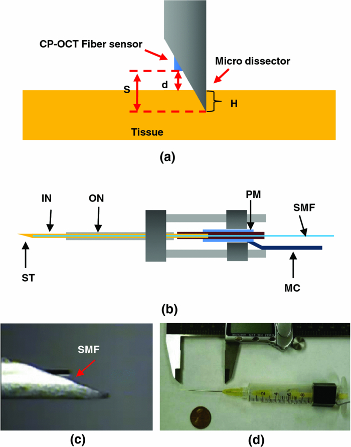 3.System ConfigurationThe overall system configuration is schematically shown in Fig. 2, which consists of three major sections: 1. The CP-LCI system; 2. the handheld tool system; 3. the motor control system. In the CP-LCI system section, a 12-bit, 2048 pixel CCD line-scan camera (e2v, EM4, USA) with a camera link interface was used as the detector of the homebuilt spectrometer. A superluminescent light emitting diode (SLED) source with the center wavelength of 845 nm and bandwidth of 105 nm worked as the light source, which gave an experimentally measured axial resolution of 3.6 μm in the air. The minimum line period was camera-limited to 14.2 μs, corresponding to a maximum line rate of 70 k A-scan/s. The spectrum data acquired by the camera is transferred to the computer through a frame grabber (National Instruments, PCI-E 1429), with multiple A-scans within one frame. As shown in the following experiment, only one A-scan of each frame is processed and used for tracking, therefore the tracking rate during the operation is eventually determined by the frame rate, which is less than the maximum line rate. In the common-path interferometer configuration, a 50/50 coupler was used and only one branch on the output worked as the common light guide for both the sample and reference signals. In the handheld tool section, a 90° cleaved single-mode fiber (5.6 /125 μm Core/Clad diameter) served as a CP-LCI sensor. A 25-gauge stainless steel needle was modified to a microdissector. The reference signal came from the Fresnel reflection at the fiber probe end. A piezoelectric linear micromotor (LEGS-L01S-11, PiezoMotor AB, Sweden) was used to drive the inner needle mounted onto the motor shaft. This linear micromotor has a 35 mm travel range, 20 mm/s maximum speed, better than 1 μm resolution, and a 10 N maximum driving force. A quad-core Dell T7500 workstation was used to host the frame grabber for the CCD camera, motor controller, and to perform both real-time signal processing and closed-loop control. The system control software is written in a hybrid architecture combining LABVIEW and self-developed dynamic-link libraries in C++. In the following tests, the CCD camera was running at 500 frames/s, corresponding to the tracking rate of 500 Hz with 2 ms interval. Figure 3 shows the control flowchart and speed control curve of the system. A closed-loop control is formed by the CP-LCI sensor and micromotor. The raw spectrum is first remapped from the λ domain to the k domain, and then processed by fast Fourier transform to get the corresponding A-scan profile (here for simplicity, only the first A-scan of each frame is processed). Then, the edge searching algorithm is applied to the A-scan signal to determine the actual CP-LCI probe-to-target distance d. Here, d needs to be divided by the refraction index n of the media, which may exist between the fiber tip and surgical target. A speed control curve is applied in the algorithm, where V(|e|) is the percentage of the motors maximum speed, e is the error between d (the actual distance), and D (the desired distance). As shown in Fig. 3a, the motor slows down with the decrease of |e| to minimize the tracking overshooting and oscillation in the control loop. 4.Motion Compensation TestFirst, we performed the surface tracking and motion compensation tests to evaluate the time response and spatial resolution. The surgical tool tip was pointed perpendicular to a target surface, which moved back and forth from the initial position. The tool tip sensed the motion and adjusted the tool tip position to keep a constant distance D = 1120 μm, and the value of e was recorded as a function of time. As shown in Fig. 4a, the benefit of the compensation is apparent when comparing the error between “Compensation off” mode and “Compensation on” mode. Figure 4b shows the zoomed-in view of the error-time curve at Compensation on mode shown in Fig. 4a. The compensation error is less than ±5 μm, which agrees well with the axial resolution of CP-LCI. 5.Precise Incision TestTo show that these tools will actually enhance the free-hand microincision accuracy, using phantoms fabricated from Intralipid, we performed surgical incisions with intended depth of 100 μm with and without the CP-LCI guidance. The Intralipid was originally 20% concentration and semi-dried to simulate the real tissue. To view and measure the incision depth relative to the phantom surface, we took 3D (three-dimensional) volumetric OCT images of the incision sites using our high speed OCT system.12 The image volume is 1000(X) ×150(Y) ×512(Z) voxels. Figures 5a, 5e show the en face projections of the incision region. The blue (left) and red (right) lines in Fig. 5a, 5e indicate the cross-sectional imaging traces of the top edge and bottom of the incisions (color online). As shown in Figs. 5d, 5h, the incision with surface tracking and compensation has a constant incision depth of about 100 μm, while the free-hand incision has irregular depth, ranging from ∼80 to ∼250 μm. Fig. 5CP-LCI guided micro-incision: (a) En face projection image of the incision region; (b) B-scan along the red trace (right line) in (a), bottom of incision; (c) B-scan along the blue trace (left line) in (a), top of incision; (d) combination of (b) and (c). The free-hand micro-incision situation is performed as (e) and (f), corresponding to (a) and (b), respectively. The green arrows on (a) and (e) indicate the incision direction. (Color online only.)  6.DiscussionAs described in Sec. 4, for the current motion compensation protocol, only the first A-scan of each frame is processed and used for tracking. Consequently, even though a speed control curve is applied, a tiny oscillation (±2 μm) still exists during the unidirectional traveling of the target, and drastic phase error (about 10 μm) happens when the target motion direction changes. A potential solution is to process all A-scans within one frame, and then apply a predictive filter to follow the motion trace of the target, and the tracking error, especially the phase error, could be potentially reduced. The GPU-based acceleration method12, 13 could be utilized to implement the real-time processing of the huge amount of raw OCT spectrum data as well as edge searching. In the real surgical environment, the desired incision depth H (and hence desired fiber tip to tissue distance D) could be determined in real-time and automatically by ultrahigh speed OCT imaging and analysis of the surgical target's microstructures, for example, using segmentation algorithm to figure out the thickness of certain retina layers.14, 15 As a very promising future direction, the handheld smart microdissector system can be used in combination with our recently developed real-time four-dimensional full-range FD-OCT system,16 where the comprehensive information of surgical tool location and target microstructure can be obtained through high speed GPU processing and feed back to control the incision depth. 7.ConclusionIn this work, a CP-LCI guided handheld microsurgical incision is demonstrated and studied. The method is capable of tracking the tissue surface and capable of compensating a typical surgeon's hand-tremor in real-time with micrometer-level precision. Using a phantom model, the quality of the incision is evaluated using 3D OCT, and the results using the surface tracking and motion compensation tool show significant improvement compared to the results using free-hand incision. Such a “smart surgical tool approach” could have broad applications in a wide range of microsurgical procedures to improve surgical accuracy and safety. ReferencesC. N. Riviere, W. T. Ang, and
P. K. Khosla,
“Toward active tremor canceling in handheld microsurgical instruments,”
IEEE Trans. Rob. Autom., 19 793
–800
(2003). https://doi.org/10.1109/TRA.2003.817506 Google Scholar
P. A. Hsu and
B. C. Cooley,
“Effect of exercise on microsurgical hand tremor,”
Microsurgery, 23 323
–327
(2003). https://doi.org/10.1002/micr.10156 Google Scholar
S. Rizzo, F. Patelli, and
D. R. Chow, Vitreo-retinal Surgery, Springer-Verlag, Berlin Heidelberg
(2009). Google Scholar
W. T. Latt, U. X. Tan, C. Y. Shee, C. N. Riviere, and
W. T. Ang,
“Compact sensing design of a handheld active tremor compensation instrument,”
IEEE Sens. J., 9 1864
–1871
(2009). https://doi.org/10.1109/JSEN.2009.2030980 Google Scholar
K. Zhang, W. Wang, J. H. Han, and
J. U. Kang,
“A surface topology and motion compensation system for microsurgery guidance and intervention based on common-path optical coherence tomography,”
IEEE Trans. Biomed. Eng., 56 2318
–2321
(2009). https://doi.org/10.1109/TBME.2009.2024077 Google Scholar
K. Zhang, E. Katz, D. H. Kim, J. U. Kang, and
I. K. Ilev,
“A common-path optical coherence tomography guided fiber probe for spatially precise optical nerve stimulation,”
Electron. Lett., 46 118
–120
(2010). https://doi.org/10.1049/el.2010.3221 Google Scholar
A. B. Vakhtin, D. J. Kane, W. R. Wood, and
K. A. Peterson,
“Common-path interferometer for frequency-domain optical coherence tomography,”
Appl. Opt., 42 6953
–6958
(2003). https://doi.org/10.1364/AO.42.006953 Google Scholar
A. Popp, M. Wendel, L. Knels, P. Knuschke, M. Mehner, T. Koch, D. Boller, P. Koch, and
E. Koch,
“Common-path Fourier domain optical coherence tomography of irradiated human skin and ventilated isolated rabbit lungs,”
Proc. SPIE, 5861 58610Q
(2005). https://doi.org/10.1117/12.632984 Google Scholar
A. R. Tumlinson, J. K. Barton, B. Povazay, H. Sattman, A. Unterhuber, R. A. Leitgeb, and
W. Drexler,
“Endoscope-tip interferometer for ultrahigh resolution frequency domain optical coherence tomography in mouse colon,”
Opt. Express, 14 1878
–1887
(2006). https://doi.org/10.1364/OE.14.001878 Google Scholar
U. Sharma and
J. U. Kang,
“Common-path optical coherence tomography with side-viewing bare fiber probe for endoscopic optical coherence tomography,”
Rev. Sci. Instrum., 78 113102
(2007). https://doi.org/10.1063/1.2804112 Google Scholar
K. M. Tan, M. Mazilu, T. H. Chow, W. M. Lee, K. Taguchi, B. K. Ng, W. Sibbett, C. S. Herrington, C. T. A. Brown, and
K. Dholakia,
“In-fiber common-path optical coherence tomography using a conical-tip fiber,”
Opt. Express, 17 2375
–2384
(2009). https://doi.org/10.1364/OE.17.002375 Google Scholar
K. Zhang and
J. U. Kang,
“Real-time 4D signal processing and visualization using graphics processing unit on a regular nonlinear-k Fourier-domain OCT system,”
Opt. Express, 18 11772
–11784
(2010). https://doi.org/10.1364/OE.18.011772 Google Scholar
K. Zhang and
J. U. Kang,
“Graphics processing unit accelerated non-uniform fast Fourier transform for ultrahigh-speed, real-time Fourier-domain OCT,”
Opt. Express, 18 23472
–23487
(2010). https://doi.org/10.1364/OE.18.023472 Google Scholar
V. Kajić, B. Považay, B. Hermann, B. Hofer, D. Marshall, P. L. Rosin, and
W. Drexler,
“Robust segmentation of intraretinal layers in the normal human fovea using a novel statistical model based on texture and shape analysis,”
Opt. Express, 18 14730
–14744
(2010). https://doi.org/10.1364/OE.18.014730 Google Scholar
D. C. DeBuc, G. M. Somfai, S. Ranganathan, E. Tátrai, M. Ferencz, and
C. A. Puliafito,
“Reliability and reproducibility of macular segmentation using a custom-built optical coherence tomography retinal image analysis software,”
J. Biomed. Opt., 14 064023
(2009). https://doi.org/10.1117/1.3268773 Google Scholar
K. Zhang and
J. U. Kang,
“Real-time intraoperative 4D full-range FD-OCT based on the dual graphics processing units architecture for microsurgery guidance,”
Biomed. Opt. Express, 2 764
–770
(2011). https://doi.org/10.1364/BOE.2.000764 Google Scholar
|