
|
|
1.IntroductionVocal fold scarring, resulting from disease, mechanical stress from overuse, or postsurgical healing, reduces the mechanical compliance of the vocal fold tissue and is a major cause of voice disorders. An estimated 2 to 6 million people in the United States alone suffer from chronic voice impairment due to vocal fold scarring.1 Unfortunately, no reliable treatment exists for restoring proper phonation to scarred vocal folds. One treatment method that has shown promise utilizes the injection of soft biomaterials aimed at restoring the proper viscoelasticity to the tissue.2–4 In scarred vocal fold tissue, the density of the tissue and the required injection pressure are likely to impair the proper localization of the injected material in the desired tissue layer, thus reducing the effectiveness of the injection treatment. To enhance the ability of surgeons to place injectables into scarred tissue with precision, we are investigating a technique that uses femtosecond laser pulses to ablate subepithelial planar voids in the vocal fold. Human vocal folds have a layered structure that consists of epithelium as the outermost layer followed by the lamina propria and the vocalis muscle. The lamina propria is often divided anatomically into the superficial, intermediate, and deep lamina sublayers.5 The superficial lamina propria (SLP) has a thin sheet of collagen fibers that are highly aligned along the length of the vocal fold in its most superficial aspect.5 Below these fibers, the SLP consists largely of amorphous ground substance (primarily proteoglycans and glycosaminoglycans) with scattered elastin and collagen fibers, fibroblasts, and other elements typical of loose connective tissue.6 As a result, the SLP is often described as having a jelly-like viscoelasticity. The SLP in humans is frequently referred to clinically as Reinke’s space. The SLP and the epithelial layer together make up the mucosa, which is the vibratory outer layer of the vocal fold responsible for phonation. Unlike adjacent respiratory mucosa, which contains ciliated and secretory cells, the vocal fold is covered by a stratified squamous nonkeratinizing epithelium, which presumably is better suited to handle the contact and vibratory stresses of phonation, coughing, and other glottal functions. During the wound healing response, scar tissue can replace the superficial mucosal layer along with deeper parts of the lamina propria. The scar tissue consists predominantly of collagen and fibronectin, both of which increase the stiffness of the mucosa and can lead to dysphonia.2 One proposed treatment method focuses on injecting soft biomaterials, such as hydrogels and microgels, to mimic the mechanical properties of healthy tissue, or to inject biologically active materials, such as hyaluronic acid, in an effort to limit collagen formation.2,7,8 Surgical experience suggests that direct injection into scarred vocal fold tissue will be difficult, particularly when the goal is to place a layer of material in a subepithelial location to recreate a pliable mucosa. We hypothesize that the creation of a planar void in the SLP will provide a functionally appropriate space for the injected material to fill. The planar void needs to cover the approximate width and length of the active area of the mucosa affected by scarring, estimated to be maximally . We hypothesize that a void will reduce the required injection pressure and improve localization of injected materials to the superficial location occupied by healthy SLP. Focused ultrafast laser pulses (mode-locked laser pulses with femtosecond or picosecond durations) are uniquely suited for creating the subsurface void. The nonlinear absorption of tightly focused ultrafast laser pulses confines ablation to the focal volume, which can be positioned inside the bulk of the tissue. Three-dimensional (3-D) confinement gives ultrafast laser ablation the ability to cut inside tissue without cutting through the surface. Furthermore, the ablation process relies upon efficient absorption and rapid buildup of a high pressure, expanding plasma/gas bubble. Since peak intensities of ultrashort laser pulses are extremely high, only small pulse energies are required to initiate ablation. During this highly efficient process, the energy of ultrashort laser pulses mainly goes into the ionization of tissue at the focal volume and for the work required to remove the ablated tissue in the form of an expanding bubble. Short duration of these processes also ensures that there is minimal heat diffusion, namely energy loss, to the surrounding tissue. Therefore, the ultrashort laser pulses reduce the energies required to initiate ablation by orders of magnitude when compared to nanosecond or longer pulse duration laser pulses and greatly minimize collateral damage to neighboring cells and tissues.9 Such a high degree of damage confinement is especially important when working with delicate tissue such as vocal folds and it may help preventing scar formation. Successful laser microsurgery of vocal fold tissue using femtosecond laser pulses has been previously demonstrated, showing the potential for subsurface ablation confined within the sublayers of the lamina propria.10 In addition to microsurgery, focused ultrafast laser pulses can be used to generate images of biological samples through multiphoton-excited fluorescence and second harmonic generation (SHG).11 Specifically, pulses in the femtosecond regime are best suited for nonlinear imaging of biological tissues because of the lower pulse energies required for signal generation. Because these techniques again rely upon the nonlinear interaction of light with tissue at high intensities, signal generation can be confined to the focal volume. This confinement results in an intrinsic depth-sectioning capability along with submicron resolution, which is sufficient to resolve the cellular and fibrous structures that define the various levels of the lamina propria. The use of low-energy femtosecond laser pulses for imaging can provide femtosecond laser microsurgery devices a means for visualizing the region of surgery with the identical field of view and resolution as the surgical laser. We have recently demonstrated fiber-based miniaturized probes for delivering femtosecond laser pulses for microsurgery, as well as nonlinear imaging.12,13 The advent of such devices opens the door for the development of new surgical applications of femtosecond laser pulses, such as the laryngeal surgical technique proposed here. For the exploratory experiments presented in this paper, we investigated the creation of thin voids within ex vivo porcine vocal fold samples using a benchtop microscope system. Our focus was on creating subsurface voids with laser parameters (i.e., spot size, scanning speed, and pulse energy) that are readily achievable in miniaturized, fiber-based optical systems and also with a single compact laser system suitable for use in a clinical environment. 2.Methods and Materials2.1.Experimental SetupWe used a home-built, benchtop, laser scanning microscope, combining microsurgery and nonlinear imaging capabilities using a single femtosecond laser system, a 500-kHz-repetition-rate erbium-doped fiber laser (Discovery, Raydiance Inc.) shown in Fig. 1. When frequency-doubled, the laser produces 750-fs pulses at 776 nm with a maximum pulse energy of 2.5 µJ. The laser is delivered into a laser scanning microscope and focused at the sample with a 0.75-NA, (Nikon Plan Apo ) for both nonlinear imaging and femtosecond laser microsurgery. We deduced the focused spot size of the laser beam by imaging 100 nm fluorescent beads and measuring the full width at half maximum (FWHM) of the two-photon point spread function (PSF). To better simulate the focusing conditions in tissue, the beads were suspended in agar gel, and the PSF was measured between imaging depths of 70 to 140 µm. The average lateral FWHM of the two-photon PSF was found to be 0.61 µm, which corresponds to a 1.47-µm diameter of the intensity distribution. The diameter of the intensity distribution is times of the FWHM of the two-photon PSF according to the work of Zipfel and colleagues.14 These values are comparable to the spot sizes achievable in our current miniaturized femtosecond laser surgery probes. For microsurgery, the laser beam was scanned by the -axis of a pair of galvanometric scanning mirrors (Cambridge Technologies, Inc.) sweeping the focal spot 235 µm at the tissue, while the sample was translated using precision stepper-motor stages (NanoMax MAX343, Thorlabs, Inc.) in the -axis for covering 235 µm of tissue. Fig. 1Schematic representation of the benchtop microsurgery microscope system for combined imaging and microsurgery. Femtosecond laser pulses are delivered from a compact fiber laser system to an energy attenuator consisting of a half-wave plate () and polarizing cube beamsplitter (PCBS). The beam is then scanned by a pair of galvanometric scanning mirrors (SM) through a scan lens (SL) and tube lens (TL), which image the mirrors to the back aperture of a 0.75-NA (OL). The laser is then used to either ablate or image the sample on a three-axis motorized stage (XYZ). Emitted light is redirected by a cold mirror (CM) through collection optics (CO) and a laser-blocking filter (F) to the photomultiplier tube (PMT). The PMT, stage, and scanning mirrors are all in communication with a personal computer through data acquisition cards, not shown. Inset: (a) Schematic of the laser scanning pattern at the sample during microsurgery. The direction of beam scanning results from translation of the sample stage (). For imaging, a similar raster pattern is employed; however, here the scanning mirrors provide beam scanning in both and directions. (b) Illustration of the degree of overlap between subsequent laser pulses during imaging and microsurgery. 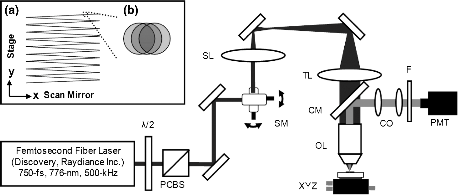 The duration of surgery is a key factor in development of a clinical technique. Our goal was to minimize the ablation duration while using low pulse energies that are deliverable through a fiber-coupled miniature system. The duration of ablation depends on the beam scanning speed, which in turn controls the degree to which sequential pulses overlap (or the distance between sequential pulses) at the focal plane. The degree of pulse-to-pulse overlap, on the other hand, determines both the ablation volume and the speed of ablation, two competing parameters that require optimization. A high degree of overlapping increases pulse-to-pulse accumulation effects, providing the desired extent of tissue ablation at low pulse energies. For a fixed repetition rate, increasing pulse overlap decreases the speed of ablation, thus increasing the time required for ablating a given region. We therefore chose to perform our experiments using four overlapping pulses in the direction by deflecting the laser beam such that 75% of the focused spot diameter overlapped the spot of the previous pulse. The length of the line scanned by the galvo-mirror on the tissue was chosen to be 235 µm, which is achievable in our miniaturized femtosecond laser systems.12,13 To achieve 75% pulse-to-pulse overlap with the 235-µm scanning length, the mirror scanning speed was 390 Hz, and the translation speed of the -axis was (resulting in one to two overlapping pulses in the -direction). For multiphoton imaging, the laser beam was scanned over a field of view using both axes of the scanning mirrors. We separated the emitted light from the laser light by a cold mirror (HT-1.00, CVI Laser), directed it into a PMT (H7422-40, Hamamatsu), and reconstructed the signal into images at a frame rate of 0.75 frames per second. This imaging speed roughly corresponds to the same 75% pulse-to-pulse overlap used during surgery. We chose to keep the laser scanning speed approximately equal for both microsurgery and imaging because most miniaturized beam scanning systems rely upon resonant actuation and exhibit optimum deflection at a fixed frequency. The use of the same scanning speed for both imaging and surgery was chosen to demonstrate that both functions could be achieved in the future by a single resonant scanning device. During imaging, we occasionally performed simultaneous two-photon fluorescence (TPF) and SHG imaging with a wavelength-tunable femtosecond laser oscillator (Mai Tai, Spectra Physics) set to 870-nm excitation wavelength and a bandpass filter () inserted before the PMT. The filter effectively blocks the majority of TPF signal generated at this wavelength while passing any frequency-doubled signal generated by SHG. This protocol enables us to determine whether the source of our signal is fluorescent or SHG in nature. We used the wavelength-tunable laser simply to access the pass-band of the filter currently used in our lab. 2.2.Ex Vivo Tissue SamplesWe acquired frozen whole porcine airway specimens from a local slaughterhouse, after which the larynx was isolated and thawed in a room-temperature saline bath. Porcine vocal folds have a layered lamina propria similar in organization and constituents to human vocal folds. Preliminary nonlinear imaging and histology of the superior (false) vocal fold showed the presence of a prominent subepithelial collagen layer in the SLP, which was not identified in the inferior fold. Because scarred human vocal fold consists of dense collagen, we chose the superior vocal fold for our experiments so as to better model the structural components and sources of the nonlinear image signal we expect to find in the first few hundred microns of scarred human vocal fold. Additionally, recent studies suggest that the superior vocal fold may play the dominant role in porcine phonation, similar to the inferior or “true” vocal fold in humans.15 After excision, the vocal fold was placed in saline and covered by a glass cover slip to flatten the upper surface. The cover slip acted to gently flatten the surface of the sample so that a uniform plane could be accessed for experimentation. In a clinical application, the glass cover slip would be akin to having the window of a microsurgery probe in contact with the sample, thus helping to maintain a constant depth of ablation. As a result of the freezing process, little cellular autofluorescence was present from which the surface of the sample could be identified during imaging. To ensure proper identification of the tissue surface, 5 µL of a solution of 1-µm fluorescent beads in saline (0.002% solids after dilution in PBS, F-8823, Invitrogen) was deposited onto the tissue surface prior to placement of the cover slip. Samples that were to be examined by follow-up histology were placed in 10 mL of 10% formalin (SF98-4, Fisher) immediately after ablation and TPF/SHG imaging and stored at 4°C for at least 48 h prior to delivery for histology preparation, paraffin embedding, sectioning, and hematoxylin and eosin (H&E) staining (TherapeUTex; Austin, Texas). 3.ResultsWe used nonlinear imaging to target the ablation within the desired tissue architecture of the vocal folds before the ablation and to verify the success of the ablation after the procedure. Figure 2 shows a representative image stack through the vocal fold mucosa of one sample before ablation. The tissue surface was readily identified by the presence of the fluorescent beads [Fig. 2(a)]. As imaging depth was increased, we detected SHG signals that appeared to correspond to highly organized and dense collagen fibers. The depth at which collagen fibers first appeared varied significantly between samples, ranging from 29 to 66 µm below the surface [Fig. 2(b)], while the depth at which the image plane was entirely within the collagen varied between 72 and 90 µm below the surface [Fig. 2(c)]. Fig. 2Representative nonlinear optical images of excised porcine vocal fold mucosa. (a) Three-dimensional (3-D) reconstruction of the image stack. Each image comprises a five-frame average, and the separation between each image is 2 µm. The punctuated bright spots on the surface are the fluorescent beads that were placed for surface identification. Total imaging depth is 120 µm, and lateral field of view is . Dotted lines in (a) represent the planes shown in (b) and (c), at depths of 46 and 72 µm below the surface, respectively. The average laser power during imaging was 0.85 mW at the surface, gradually increasing to 4.35 mW at a depth of 120 µm below the surface. In (c), the imaging plane is entirely within the collagen, and the straight, strongly aligned fibers can be clearly seen. 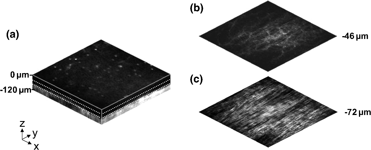 We verified whether the fibers were indeed collagen, rather than elastin, through use of the SHG differentiation protocol described earlier. The images with and without the filter at constant imaging power demonstrated equal signal intensity, indicating that the signal source was SHG and not TPF; collagen fibers are well known sources of SHG, whereas nonlinear optical signal from elastin fibers is due to the more broadband TPF.16 The identification of a large amount of collagen highly oriented along the length of the vocal fold is consistent with the structure of the upper SLP in porcine vocal fold.17 We therefore determined the collagen interface as the interface of the epithelial and SLP layers and chose it as our desired plane of ablation. We investigated subsurface void formation by irradiating a series of squares at the epithelium—SLP interface using pulse energies of 50, 100, 500, and 750 nJ. These pulse energies correspond to fluences of approximately 3, 6, 30 and , respectively. The size of the ablation was chosen so that the entire region of interest could be visualized before and after ablation in the field of view of the multiphoton microscope. In some cases, nonlinear optical imaging 1 min after ablation revealed a region or regions of signal loss. We considered these dark regions as the location of the photo-disrupted area and classified them as voids or bubbles. Because the source of the collagen imaging signal is SHG, we can rule out photobleaching as the cause of lost signal in this region. Furthermore, we observed deflection of the surrounding collagen in cases of larger voids, supporting the view that bubble expansion occurred rather than a photochemical depolymerization of collagen. Figure 3 presents a representative example of a sample ablated with 100-nJ pulses. While we did not observe any noticeable tissue modification using 50-nJ pulses, irradiation with 100-nJ pulses produced a very thin plane of induced luminescence around the photo-disrupted region and occasionally small localized voids within that region. Figure 3 shows the induced luminescence after ablation with 100-nJ laser pulses. When a notch filter was employed to filter out broadband fluorescent emission as before, this luminescence signal could not be detected. The broadband nature of the luminescence signal indicates that it is fluorescent in nature rather than due to an enhancement or generation of second harmonic signal. This luminescence border appeared long-lived and could still be observed 1 h after ablation. Though the mechanism behind the increased luminescence has yet to be determined, this phenomenon has been observed by several other groups using fluorescence imaging to visualize femtosecond laser ablation of tissue.18–20 Fig. 3Irradiation using 100 nJ pulses. (a) Second harmonic generation (SHG) images of collagen structure show the plane, 36 μm below the surface, targeted for ablation just prior to irradiation. (d) The same field of view, 1 min after irradiation with 100-nJ pulses. Cross sections through the centerlines of (a) and (d) are provided in (b) and (c), and (e) and (f), respectively. Arrows in cross-section images indicate the imaging planes of (a) and (d). In (d), note both the square region of induced luminescence corresponding to the size of the ablated region and the two circular regions resulting from localized bubble nucleation during irradiation. Two dashed circles highlight what appear to be disrupted fibers in the collagen layer, suggesting that a thin subresolution plane may have been disrupted at this energy. Imaging depth in both sets of images is 96 µm. Scale bars are 100 µm.  At low laser fluences near the damage threshold, the extent of ablation can be smaller than the spot size of the focused laser beam. When the imaging resolution is similar in size to the surgical ablation, near-threshold voids, such as those created by 100-nJ pulses, would likely be difficult to identify since they would be smaller than the imaging resolution. Accordingly, we did not observe any single large void with 100-nJ laser pulses, but instead we occasionally observed small voids in the tissue. These voids most often occurred at the beginning or end of the ablation region and likely resulted from these areas receiving increased exposure. Less frequently, small bubbles were observed in the middle of the region of ablation. These bubbles were likely a result of inhomogeneity in the tissue that gave rise to a slightly lower breakdown threshold at certain locations. Both cases can be seen in the example shown in Fig. 3(d). The presence of induced luminescence and occasional bubble nucleation indicates that the tissue was modified when using pulses as low as 100 nJ. However whether or not the scanned regions were entirely ablated at this energy or less will require a secondary means of verification, such as histology. Higher pulse energies generally resulted in the formation of larger voids within the tissue. The use of 500- and 750-nJ pulses created large voids that covered the scanned region of ablation and extended above and below the plane of ablation. We theorize that these large voids are caused by long-lasting bubbles created at the plane of ablation that then merge and expand, displacing the tissue above and below the ablation plane. The formation of bubbles that expand beyond the focal volume is consistent with femtosecond laser ablation well above the optical breakdown threshold. Increased pulse energy beyond the threshold leads to increased maximum bubble diameter. The larger amount of vaporized biomolecules produces a volume of gas that cannot be condensed and must diffuse, leading to longer bubble lifetimes.9 Figure 4 illustrates a representative example using 500-nJ pulses. In this case, the subsurface void has maximum dimensions in the ablation plane of and has a maximum height of 108 µm. In one case, shown in Fig. 5, a similar void created by scanning 750-nJ pulses was then monitored continuously for 45 min after ablation. The void was initially measured to be approximately in the targeted ablation plane and extended 48 and 54 µm above and below this plane, respectively. Over the next 45 min, the bubble was observed to collapse until it measured only 48 µm at its thickest point. The remaining void, shown in Fig. 6, covered an area of approximately , similar to the target dimensions. However, the planar void exhibited a tilt out of the plane of ablation toward the surface of the tissue. Over the 275-µm extent of the ablation, the void rose just over 60 µm and nearly broke the plane of the tissue surface. We did not observe any tilt in the induced luminescence of the 100-nJ cases, which rules out tilting of the sample stage as the source of tilt in the ablated void. This tilt is likely caused by incoming surgery pulses interacting with the long-lasting bubbles created with the previous, high-energy pulses. Fig. 4Subsurface void formation with 500-nJ pulses. (a) Second harmonic generation (SHG) images of collagen structure show the plane, 72 μm below the surface, targeted for ablation just prior to irradiation. (d) The same field of view, approximately 1 min after irradiation with 500-nJ pulses. Cross sections through the centerlines of (a) and (d) are provided in (b) and (c), and (e) and (f), respectively. Arrows in cross-section images indicate the imaging planes of (a) and (d). Note that in (e) and (f), the induced luminescence at the periphery of the ablated void is apparent. Total imaging depth in (c) and (b) was 96 µm, while in (e) and (f) total imaging depth was increased to 192 µm to fully capture the void. Scale bar is 100 µm.  Fig. 5Time-lapse images after ablation by 750-nJ pulses. The images show the plane located 18 µm below the targeted ablation plane. Time stamps in the upper left corner denote how much time has elapsed since irradiation. In the first image, a large void is observed, corresponding roughly to the size and shape of irradiation but clearly extending below the targeted ablation plane. As time progresses the void appears to recede, allowing the collagen that had been displaced to relax and return to the field of view. Corresponding plane and cross-section views of the ablation plane after the 45 min are shown in Fig. 6. Scale bar is 100 µm.  Fig. 6Subsurface void formation with 750-nJ pulses. (a) Second harmonic generation (SHG) images of collagen structure show the plane, 78 μm below the surface, targeted for ablation just prior to irradiation. (d) The plane targeted for ablation approximately 45 min after irradiation, once the void had mostly collapsed. Cross sections through the centerlines of (a) and (d) are provided in (b) and (c), and (e) and (f), respectively. Arrows in cross-section images indicate the imaging planes of (a) and (d). After irradiation with 750-nJ pulses, a large void was observed which then collapsed over 45 min, shown in Fig. 5. Note that in (e) and (f), the induced luminescence at the periphery of the ablated void is apparent. Also, note the tilting of the void in the plane in (e). During ablation, laser scanning progressed in the positive direction. The apparent rise of the ablation during the ablation process is attributed to the interaction of incoming laser pulses with the preexisting bubble from previous pulses. Total imaging depth in both sets of images is 144 µm. Scale bar is 100 µm.  Last, we ablated a series of voids using 500-nJ pulses, spaced 100 µm apart, at a fixed depth of 120 µm beneath the surface to examine by follow-up histology. The appearance of the voids identified in histology (Fig. 7) correlate well with the in situ images taken by nonlinear optical imaging. Figure 7(a) presents a cross-sectional image reconstructed from nonlinear optical images of one void in the series, taken approximately 25 min after ablation. From this image, the void appears to be localized entirely within the collagen layer, with a centerline depth of 116 µm and a length of 215 µm. Estimated uncertainty of the measurements from image size calibration is approximately . The same void was identified during follow-up histology [Fig. 7(b)], exhibiting similar epithelial morphology, and measured centerline depth and length of 99 and 175 µm, respectively. For histological analysis, the estimated uncertainty is approximately . The histological measurements agree well with the in situ measurements considering that the tissue is expected to contract during the histology preparation. In this histology image, no visible modification was identified in the cell layers above the ablated void. Another void in the series [Fig. 7(c)] occurred underneath a thinner portion of epithelium and even separated a small number of epithelial cells. Interestingly, the void beneath the thinner section of epithelium is much thicker, indicating that the reduced epithelial scattering allowed more energy to reach the focal plane, subsequently increasing void dimensions. By cutting into a small part of the epithelial layer, this void provided further evidence that the spaces identified in histology are in fact ablated voids (rather than, perhaps, an abnormally shallow blood vessel). To ensure the epithelium is not disrupted in clinical use, future voids should be created at deeper depths below the tissue surface. Fig. 7Histological follow-up of voids created with 500-nJ pulses. (a) Cross-sectional second harmonic generation (SHG) image of a void ablated approximately 120 µm beneath the tissue surface. Arrows denote the plane targeted for ablation. (b) Follow-up histology of the void shown in (a). Arrow indicates subepithelial void created by femtosecond laser ablation. (c) Histology section of a different void in the series. Arrow indicates small section of basal-layer cell nuclei that were separated from the epithelium during femtosecond laser ablation. Note the thicker void and the thinner epithelium in comparison with (c). Histology images are stained by H & E. All scale bars are 50 µm.  4.DiscussionThe imaging and void formation observed in these experiments demonstrate the potential for a femtosecond laser-assisted microsurgery/imaging technique for vocal fold restoration. By utilizing the damage confinement properties of femtosecond laser ablation, planar voids could be created near the epithelium–SLP boundary, which may aid in the localization of injected biomaterials. With the use of lower energy pulses from the same laser system for nonlinear optical imaging of the sample, the structure and orientation of collagen fibers can be clearly distinguished. In addition to determining the tissue type at a given depth, this ability may be useful in identifying scarring in the vocal fold, where scarring is expected to manifest as dense, but less organized, collagen infiltrating throughout the SLP. Additionally, the induced luminescence phenomenon that we observed always accompanied void formation and was localized in the 3-D periphery of the ablated region. In clinical applications, it may be possible to use the induced luminescence as a signal source to determine the extent of successful ablation. For this use, further histology of near-threshold ablations or a better understanding of the induced luminescence mechanism may be required to ensure that the presence of induced luminescence always indicates successful ablation. It is possible that, just below the ablation threshold, the energy is sufficient for generation of luminescence but not ablation. Ablation using larger pulse energies well above the optical breakdown threshold produced voids that expanded significantly above and below the plane of ablation. Creating large voids may be advantageous for localizing injected materials as they should increase the likelihood of correctly locating the void during injection. In the envisioned application, the biomaterial is expected to track away from and along the injection needle during injection until it encounters the void, which will then fill selectively as it is the path of least resistance. In the case of the 750-nJ-irradiated void, shown in Figs. 5 and 6, we observed that the void bubble lasted 45 min, which provides more than ample time for injection. The interaction of surgery pulses with an expanding bubble from previous pulses appears to have caused the ablated void to rise away from the plane of ablation toward the tissue surface. This tilt needs to be avoided for clinical applications, as it would prevent localization of the void in a consistent tissue layer over the 10 mm maximum anticipated ablation length. To reduce this source of tilting of the ablation plane, the pulse energy can be decreased, as shown in the 100-nJ case, or the slow-axis speed of ablation can be increased to provide more separation between lines of ablation. The second option is most likely preferable for clinical application where the clinician may wish to ensure continuous ablation and a larger void. As previously mentioned, by maintaining a constant beam scanning speed for imaging and ablation, a single resonant scanning device could be used to provide beam scanning within a clinical manifestation of this technique. Many miniaturized scanning systems, such as microelectromechanical system (MEMS) mirrors and piezoelectric fiber scanners, exhibit optimum deflection on resonance, and the use of a single scanning device can greatly reduce complexity and final packaging size. The ablation dimensions are also consistent with the field of view of our initial femtosecond-microsurgery probe prototype.12 The maximum pulse energy deliverable by our previous device was 350 nJ; however, the use of a reflective coating on the MEMS scanning mirror would easily increase the maximum energy to over 900 nJ. Further improvements can be gained by increased stretching of the pulse prior to fiber coupling to avoid damage to the fiber tip, which can greatly reduce coupling efficiency. The stretching of the pulse was the limiting condition in our previous study for achieving higher energy delivery through the fiber. A longer length of air-core fiber can then be used to ensure proper recompression of the pulse at the sample, as was demonstrated in our most recent probe prototype.13 The objective lens used in this study provided a measured spot size of 1.47 µm inside an agar phantom at the depths we investigated in our study. For comparison, point-spread function measurements using a 0.8-NA miniaturized aspheric lens with 3-mm diameter in our tabletop microscope achieve a 1.1 µm focal spot diameter,13 indicating that these spot sizes can be readily achieved in miniaturized femtosecond laser systems. With use of the scanning parameters and the 500-kHz pulse repetition rate employed in this study, a area could be ablated in just under 3 min, which is considered acceptable for clinical use. For comparison, the same scanning parameters coupled with a 1-kHz rate common to most chirped-pulse amplification (CPA) systems would require over 24 h to ablate the same region, making these systems unrealistic for clinical microsurgery or imaging with regard to this application. Pulse repetition rates of hundreds of kilohertz are well-suited for this application, as these systems can easily be used for both imaging and microsurgery above optical breakdown. Fiber laser systems such as the one used in this study are particularly well-suited for clinical applications, since they are often much more compact and robust than CPA systems. 5.ConclusionWe have demonstrated the use of a single, compact, high-repetition-rate femtosecond laser system for imaging and microsurgery of porcine vocal fold as a first step toward the development of an ultrafast laser-assisted method of treating scarred vocal folds in humans. Preliminary experiments show that large long-lasting subsurface voids can be created and that collagen fiber organization can be clearly resolved, all using laser conditions achievable in a miniaturized fiber-based probe. Future steps will include follow-up histology of near-threshold ablation conditions and investigation of the maximum depth of ablation. Our goal is to now use a scar model to determine the degree to which the voids reduce injection pressures and localize injected biomaterials. AcknowledgmentsThis work was supported by grants from the National Science Foundation (IDR: CBET-1014953 and Career Award: CBET-0846868) and a grant from the Texas Ignition Fund. The authors would like to thank Raydiance, Inc. for use of their Discovery fiber laser, as well as Dr. R. Rox Anderson and Dr. Nicholas Durr for consultation. ReferencesL. O. RamigK. Verdolini,
“Treatment efficacy: voice disorders,”
J. Speech Lang. Hear. Res., 41
(1), S101
–S116
(1998). 1092-4388 Google Scholar
S. Hirano,
“Current treatment of vocal fold scarring,”
Curr. Opin. Otolaryngol. Head Neck Surg., 13
(3), 143
–147
(2005). http://dx.doi.org/10.1097/01.moo.0000162261.49739.b7 1068-9508 Google Scholar
S. M. ZeitelsG. B. Healy,
“Laryngology and phonosurgery,”
New Engl. J. Med., 349
(9), 882
–892
(2003). NEJMBH Google Scholar
S. M. Zeitelset al.,
“Foresight in laryngology and laryngeal surgery: a 2020 vision,”
Ann. Otol. Rhinol. Laryngol., 116
(Supplement 198), 2
–16
(2007). AORHA2 0003-4894 Google Scholar
J.-M. Pradeset al.,
“Lamina propria of the human vocal fold: histomorphometric study of collagen fibers,”
Surg. Radiol. Anat., 32
(4), 377
–382
(2010). http://dx.doi.org/10.1007/s00276-009-0577-9 0930-1038 Google Scholar
T. H. Hammondet al.,
“The intermediate layer: a morphologic study of the elastin and hyaluronic acid constituents of normal human vocal folds,”
J. Voice, 11
(4), 59
–66
(1997). JOVOEA Google Scholar
M. S. Hahnet al.,
“Collagen composite hydrogels for vocal fold lamina propria restoration,”
Biomaterials, 27
(7), 1104
–1109
(2006). http://dx.doi.org/10.1016/j.biomaterials.2005.07.022 BIMADU 0142-9612 Google Scholar
X. Q. Jiaet al.,
“Hyaluronic acid-based microgels and microgel networks for vocal fold regeneration,”
Biomacromolecules, 7
(12), 3336
–3344
(2006). http://dx.doi.org/10.1021/bm0604956 BOMAF6 1525-7797 Google Scholar
A. Vogelet al.,
“Mechanisms of femtosecond laser nanosurgery of cells and tissues,”
Appl. Phys. B, 81
(8), 1015
–1047
(2005). http://dx.doi.org/10.1007/s00340-005-2036-6 APBOEM 0946-2171 Google Scholar
H. Wiswehet al.,
“Optical coherence tomography monitoring of vocal fold femtosecond laser microsurgery,”
in Therapeutic Laser Applications and Laser-Tissue Interaction III,
6632071
–6632077
(2007). http://dx.doi.org/10.1117/12.728139 Google Scholar
W. R. ZipfelR. M. WilliamsW. W. Webb,
“Nonlinear magic: multiphoton microscopy in the biosciences,”
Nat. Biotechnol., 21
(11), 1368
–1376
(2003). http://dx.doi.org/10.1038/nbt899 NABIF9 1087-0156 Google Scholar
C. L. Hoyet al.,
“Miniaturized probe for femtosecond laser microsurgery and two-photon imaging,”
Opt. Express, 16
(13), 9996
–10005
(2008). http://dx.doi.org/10.1364/OE.16.009996 OPEXFF 1094-4087 Google Scholar
C. L. Hoyet al.,
“Optical design and imaging performance testing of a 9.6-mm diameter femtosecond laser microsurgery probe,”
Opt. Express, 19
(11), 10536
–10552
(2011). http://dx.doi.org/10.1364/OE.19.010536 OPEXFF 1094-4087 Google Scholar
W. R. ZipfelR. M. WilliamsW. W. Webb,
“Nonlinear magic: multiphoton microscopy in the biosciences,”
Nat. Biotechnol., 21
(11), 1369
–1377
(2003). http://dx.doi.org/10.1038/nbt899 NABIF9 1087-0156 Google Scholar
F. AlipourS. Jaiswal,
“Phonatory characteristics of excised pig, sheep, and cow larynges,”
J. Acous. Soc. Am., 123
(6), 4572
–4581
(2008). http://dx.doi.org/10.1121/1.2908289 JASMAN 0001-4966 Google Scholar
A. Zoumiet al.,
“Imaging coronary artery microstructure using second-harmonic and two-photon fluorescence microscopy,”
Biophys. J., 87
(4), 2778
–2786
(2004). http://dx.doi.org/10.1529/biophysj.104.042887 BIOJAU 0006-3495 Google Scholar
C. Boudouxet al.,
“Preliminary evaluation of noninvasive microscopic imaging techniques for the study of vocal fold development,”
J. Voice, 23
(3), 269
–276
(2009). JOVOEA Google Scholar
K. KönigO. KraussI. Riemann,
“Intratissue surgery with 80 MHz nanojoule femtosecond laser pulses in the near infrared,”
Opt. Express, 10
(3), 171
–176
(2002). OPEXFF 1094-4087 Google Scholar
J. A. GalbraithM. Terasaki,
“Controlled damage in thick specimens by multiphoton excitation,”
Mol. Biol. Cell, 14
(5), 1808
–1817
(2003). http://dx.doi.org/10.1091/mbc.E02-03-0163 MBCEEV 1059-1524 Google Scholar
B. G. Wanget al.,
“Multiphoton microscopy for monitoring intratissue femtosecond laser surgery effects,”
Lasers Surg. Med., 39
(6), 527
–533
(2007). http://dx.doi.org/10.1002/(ISSN)1096-9101 LSMEDI 0196-8092 Google Scholar
|


