|
|
1.IntroductionOvarian cancer is the predominant gynecological cancer in the United States with an estimated 14,240 deaths in 2016.1 The total number of new cases diagnosed in 2016 was estimated at 22,280. Only 15% of these were detected at an early (localized) stage due to lack of symptoms. The American Cancer Society states a 5-year survival rate of 92% when ovarian cancer is detected in the localized stage. However, the majority of new cases are detected at a later stage, leading to an overall survival rate of less than 46%. At this time, there is not an accurate screening method for early detection, which leads to many high-risk patients. Development of medical imaging devices capable of assisting in the early detection of cancer will increase the rate of early detection. To be effective, imaging instruments should be non- or minimally invasive with high imaging resolution, have a simple, low cost design, and be robust enough to withstand the surgical sterilization processes, such as hydrogen peroxide gas plasma. Optical imaging systems are capable of providing imaging resolution that surpasses that of pelvic ultrasound systems, which are currently used for high-risk patient evaluation. Optical coherence tomography (OCT) imaging systems are capable of resolutions ranging from 2 to with imaging depths between 1 and 2 mm.2–5 Confocal microscopy is capable of providing resolutions better than with an imaging depth of a few hundred microns.6–8 Fluorescence imaging techniques are often employed for biomedical imaging to label suspect tissue regions and improve image contrast.9–11 Second harmonic generation imaging microscopy is an optical imaging modality capable of imaging live cells and tissues. This method utilizes high power laser light that interacts with the specimen and nanobiomarkers to generate second harmonic light.12–14 Coherent Raman scattering microscopy consists of two types of techniques, stimulated Raman scattering and coherent anti-stokes Raman scattering. These methods allow for imaging of lower signal levels inherent to spontaneous Raman imaging and for vibrational imaging of living cells.15,16 Each of these methods requires a scanning technique to collect a three-dimensional image stack, which may not be able to be viewed simultaneously or requires postprocessing to incorporate each image. They also require relatively high power laser illumination, which adds to safety issues and cost. Volume holographic imaging (VHI) is a technique capable of simultaneous imaging of multiple tissue surfaces through the use of a multiplexed volume holographic element that does not require mechanical scanning.17–23 The number of simultaneous depth views is determined by the number of gratings being multiplexed into the holographic element, and reports of 2 to 5 depths have been reported using the multiplexing techniques.24 As an optical system that is capable of concurrent visualization of surface and subsurface tissue structures, the development of endoscopic VHI systems can assist in reducing the number of unnecessary surgical procedures, such as prophylactic oophorectomies. A benchtop version of the VHI has been shown to be a beneficial tool for ex vivo imaging evaluation of precancerous and cancerous tissues using reflectance and fluorescence imaging modalities.25 The contribution of this paper is the design, development, and characterization of a reflectance VHI endoscope system approved for in vivo clinical use. 2.Ovary Imaging RequirementsIt is suspected that irregularities in the epithelial layer of the ovary provide indications of early stage cancer.26 For clinical applications, the ability to view the surface of the epithelial layer and a layer 50 to below the surface can provide clinicians important information of tissue abnormalities. Therefore, the system is optimized, so the image of the tissue surface and depth takes up half the aperture of the camera and determines the maximum field of view (FOV) of the system when one camera is used. For visualization of stained nuclei and microstructural features, such as blood vessels and abnormal cysts, an optical resolution of is required and is used as the resolution requirement of the system. The length and diameter of the endoscopic probe are critical design requirements. The probe should have a minimum length of 250 mm protruding from the handle segment to provide access to the ovary during laparoscopic procedures, and the probe diameter should be less than 5 mm to be compatible with standard surgical trocars. The FOV of the system should have a minimum size of 0.5 mm by 1 mm to allow for imaging of a suspect 5 mm square area in less than 1 min. A summary of the system requirements is listed in Table 1. Table 1Desired endoscope specifications for in vivo use.
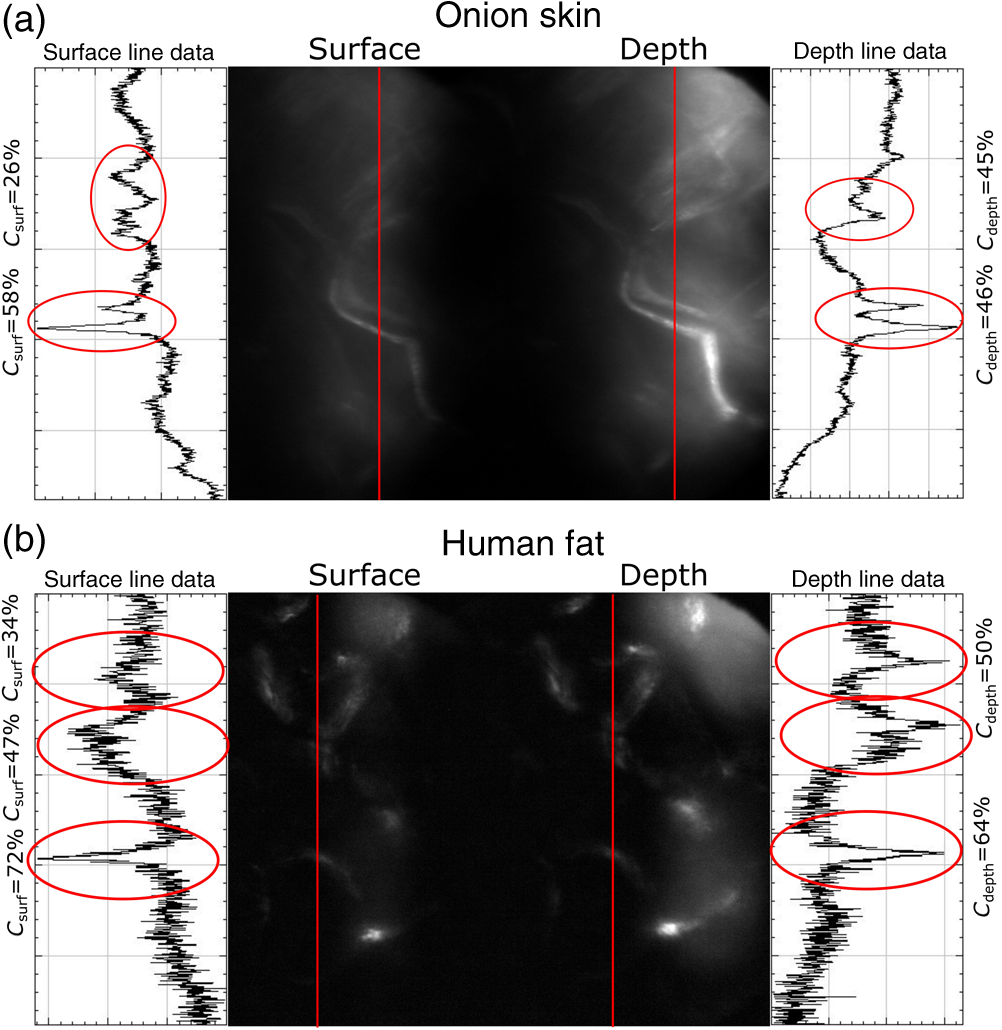
3.VHI System DesignThe VHI endoscope was designed with commercially available optics and a custom multiplexed volume holographic element formed in a PQ-PMMA material.27,28 Since the VHI system will be used in a surgical setting, component weight and size were critical design factors. The handheld portion of the system was required to fit into a sterile sleeve and allow for easy assembly of the surgically sterilized endoscopic probe while in the operating room. 3.1.Endoscope OpticsThe endoscope probe section is designed as a rigid, unit magnification, optical relay to reimage in vivo tissue to the handle optics for magnified visualization. Several rigid endoscope designs were considered for this application, and a gradient index (GRIN) probe design was chosen to reduce the number of optical elements to minimize back reflection with common path lillumination.29–33 The endoscope probe consists of three GRIN optical elements and two optical windows. GRIN optics are specified by their pitch parameter, which relates to the number of full sinusoidal periods of the light within the rod. The selected GRIN elements were obtained from GoFoton and have a pitch of 2 for the relay rod and 0.25 for the lenses.34 The two pitch relay optic was selected to accommodate the 250-mm minimum laparoscopic probe requirement since this optic has a length of 281.4 mm. The two GRIN lenses started with a 0.25-design that is designed to collimate the light from a point source. The lengths of the lenses were fabricated to accommodate the glass windows used in the system. The imaging lens has a length of 5.78 mm (0.204 pitch) to account for the 0.8-mm-thick N-BK7 window (3 mm diameter) used to provide separation between the GRIN lens and the patient. The coupling lens has a length of 5.72 mm (0.202 pitch), so the final image forms outside the 0.8-mm AR-coated window surface, leading an in-contact imaging approach with a working distance of 0. All three GRIN components have a diameter of 2.7 mm while the windows are 3 mm in diameter. These elements are shown in Fig. 1 and are labeled as follows from distal tip to proximal end: imaging lens (GoFoton ILW-2.70), relay lens (GoFoton SLR-2.70), and coupling lens (GoFoton ILW-2.70). Fig. 1Schematic of the endoscopic probe composed of GRIN lenses. Grin components have diameters of 2.7 mm, and the windows have a diameter of 3.0 mm. The theoretical optical path from an object placed in contact with the imaging lens, being relayed through the GRIN rod, and exiting to form an image outside the window on the coupling lens side is shown.  The components of the endoscope probe were assembled using EpoTek 301 epoxy with a refractive index of , which provides a good index match for the optical components.35 EpoTek 301 is a nontoxic epoxy conforming with ISO 10993 biocompatibility testing requirements and was selected due to its good optical properties and ability to withstand sterilization procedures in hydrogen peroxide gas plasma systems.36 The clarity of the epoxy was verified through a series of sterilization runs on epoxy droplets placed between glass slides and GRIN lens components. The GRIN assembly of the endoscope probe is secured in an 11-gauge stainless steel hypodermic tube (MicroGroup). The hypodermic tube assists with GRIN rigidity and increases the outer diameter of the GRIN section to 3.05 mm, matching that of the window segments for better centering while placing the window components. The full window and GRIN assembly is then epoxied into a 9-gauge hypodermic tube, giving the probe a final outer diameter of 3.8 mm. The fully assembled probe is mounted onto an aluminum clamp and the threaded retaining section, as shown in Fig. 2. Fig. 2SolidWorks rendering of the endoscope assembly indicating the endoscope probe, fabricated clamp, and threaded retainer. The threaded retainer is threaded to match the 30 mm cage mounted components. This allows for quick connection to the handle section.  The GRIN lens parameters chosen for the design are not available in the optical design program lens database, so a full comprehensive optical software model has not been realized. The finalized design of the system made use of standard GRIN equations and theory combined with paraxial modeling using Gaussian beam parameters and ABCD matrices for on-axis light.37 3.2.Handle OpticsThe handheld elements are composed of standard 30-mm-width cage mounted components from ThorLabs.38 The preliminary design of the handle started with a simplified version of the benchtop model.25 Weight was minimized by a selective choice of components, while keeping pupil matching requirements. An optical model of the simplified system configuration is shown in Fig. 3. This initial model allowed for the miniaturization of the benchtop system and determination of the geometrical optics parameters for the system. Fig. 3ZEMAX schematic of the handle layout. The surface (solid blue) and depth (dashed green) images in the inset are shown to originate from on-axis positions in the object and are then displaced by the holographic element to fill two regions on the camera as indicated by text in at the camera plane. Spacing of the lens elements are provided in the dashed brackets.  The endoscope probe relays the image of the object to the focal plane of the microscope objective. The objective is an Olympus ULWD MSPlan with and a focal length of 3.6 mm. The desired magnification was chosen such that the Nyquist criterion is met, i.e., more than 2 pixels are used per resolvable point in object space. The camera is a Thorlabs DCC3240N with a array of square pixels.38 To provide a system that will meet the Nyquist criterion while allowing for image degradation from aberrations, the smallest feature on a high resolution bar target with a width of ( per line pair) is used to set the magnification. For the system to satisfy the Nyquist criterion, the line in object space will need to take 2 pixels on the camera () and a magnification of . Since the focal length of the high NA objective lens is fixed, the camera lens is chosen through back calculation of the magnification equation, , giving a camera lens focal length of 48.92 mm. A focal length of 50 mm was selected since it is a more common lens focal length and resulted in a system magnification of 13.9. Light exiting the microscope objective enters a symmetric afocal relay of achromatic doublets (Thorlabs AC254-075-A, AC254-100-A). The relay was configured for 1:1 imaging to image the pupil of the microscope objective at the hologram plane, which allows the hologram to be the limiting aperture of the system and reduces beam overfill issues.18 The holograms used in the VHI system must provide high diffraction efficiency in a single diffraction order with high angular and wavelength selectivity. These characteristics can be achieved using volume holograms.39,40 To ensure that these characteristics are satisfied, the individual gratings in the multiplexed holograms are designed to have a volume parameter of , where is the period of the volume grating, is the reconstruction wavelength, is the thickness of the hologram, and is the index of refraction.39 The hologram was fabricated in thick phenanthraquinone-doped poly methacrylate (PQ-PMMA), with a measured index of refraction of . The grating periods for the surface and depth holograms are and and have parameters of 23817 and 22110. Since these values are well above the condition, volume holograms can be modeled using approximate coupled wave theory as described by Kogelnik.39 The resulting holograms have high diffraction efficiency, , in a single diffraction order and high angular and wavelength selectivity. The diffraction efficiency for volume phase transmission holograms sed in the VHI system is given by (with ).39 In these equations, and , where and are the reconstruction and diffracted beam angles, respectively. The hologram angular and wavelength selectivity are determined from the detuning parameter , where and are the angular and wavelength deviations, respectively, from the hologram Bragg condition that causes the diffraction efficiency to decrease to zero. The multiplexed volume hologram was fabricated using the system shown in Fig. 4. The object beams are formed by focusing a collimated beam through a microscope objective to form a point source. The microscope objective is translated a distance of between each exposure to sample light from a different tissue depth. A collimated reference beam is rotated to a different angle for exposure with each object beam to form a distinct grating within the multiplexed volume hologram. Fig. 4Recording geometry of the multiplexed hologram. The recording angle of the object beam, , is constant at 33.4 deg for both recordings. The reference beam angle, , changes between 34.92 deg and 31.88 deg for the surface and depth, respectively.  The holograms were recorded with an Argon laser (Coherent Innova 300) at a wavelength of 514 nm and designed to operate at a wavelength of 660 nm light with an inter beam angle of 90 deg between the object and reference beams.41 The angles for object and reference beams with 514.5 nm light are determined from the -vector or Bragg matching relation: , where and are the reference and object propagation vectors, respectively, and is the grating vector that has a magnitude of . The object beams for both the surface and depth channel are at an angle of 33.4 deg in air relative to the normal to the hologram surface. The reference beam angles for the surface and depth channels are 34.92 deg and 31.88 deg, respectively. Each hologram in the multiplexed element samples light from a different object depth in the tissue sample. For this system, light is sampled at the object surface and below the surface. Both the surface and depth channels are recorded with curved wavefronts that have the total curvature split with equal but opposite directions of curvature for the two imaging depths. This recording configuration allows for the separation, , to be balanced between the two channels and provides equal amounts of induced hologram aberration that results from the difference between the recording and reconstruction wavelength (e.g., 514.5 nm for recording and 660 nm for reconstruction). The measured diffraction efficiencies for the multiplexed holographic elements, tested with 633-nm laser light, are 42% and 50% for the surface and depth holograms, respectively. The angular selectivity of the holograms is , and the wavelength selectivity, . Each hologram in the multiplexed element diffracts light at two angles separated by to which are then collected by a camera lens (Thorlabs AC254-050). The lens images the diffracted light from each depth to the two rectangular areas at the camera plane. The surface and depth images each occupy half of the camera aperture (), corresponding to an FOV of after taking into account the system magnification of 13.9. A SolidWorks rendering of the handle system is shown in Fig. 5. 3.3.Light SourceThe illumination for the system is provided by a 660-nm light-emitting diode (LED) with a full width half max spectral bandwidth of 20 nm. The VHI method is not as susceptible to speckle degradation as other methods such as OCT because VHI does not rely on sensing the coherent interference effects of the detected signal but instead simultaneously projects an image across many pixels of a camera aperture.42,43 The LED is coupled into a , core fiber (Thorlabs M29L05), which carries the light from the source box to the handle setup, as shown in Fig. 6. To achieve Köhler style illumination, a 10-mm focal length asphere (Thorlabs ACL1210) and a 50-mm achromat (Thorlabs AC127-050-A) are placed after the fiber output to expand the beam to a size of 4 mm to match the microscope objective pupil. The source is placed into the main beam path using a pellicle beam splitter component with 50:50 R/T at 635 nm (Thorlabs CM1-BP150). With this setup, light exiting the microscope objective and entering the endoscope assembly has a planar wavefront in a common path configuration to simplify the design. 4.System PerformanceThe resolution of the handle optics without the hologram and endoscope probe was evaluated to be with a 1951 USAF resolution target. The resolution was measured before and after sterilization with a low-temperature hydrogen peroxide gas and was found to have the same image value. The results shown in Fig. 7(a) are used as a reference to determine system performance as the hologram and endoscope probe are added to the system. The probe assembly is aligned to the handle objective using an slip plate and -axis micrometers. The best focus location for the probe is determined by index matching the USAF resolution chart to the probe using water as an index matching fluid. Once the surface focus is achieved, the slip plate is locked down to the cage plate using set screws. Figures 7(b) and 7(c) show the group 7 region of the USAF resolution chart with the surface channel and depth channel in focus, respectively. The focus of the depth channel was determined by moving the target past the focus of the surface image. As shown in Figs. 7(b) and 7(c), the smallest resolvable bar target is group 7, element 6, corresponding to or per line pair for both the surface and depth channels. Fig. 7(a) Resolution test of handle components prior to addition of volume hologram and endoscope probe relay. The smallest target available on the chart is group 9, element 3 with a size of (). (b) Surface channel focus, (c) depth channel () focus [both (b) and (c) show or better resolution with the hologram and endoscope probe added]. 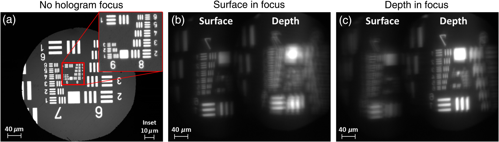 The resolution limit was quantified by evaluating the contrast of features in the 1951 USAF resolution chart. Targets with a contrast are considered to be resolvable. The values calculated for the resolution chart shown in Fig. 8 are taken from an average of vertical slices through each element of the horizontal line targets. Fig. 8Contrast calculations for the group 7 elements in the USAF resolution chart. The lowest contrast content seen in the chart is at 14%. 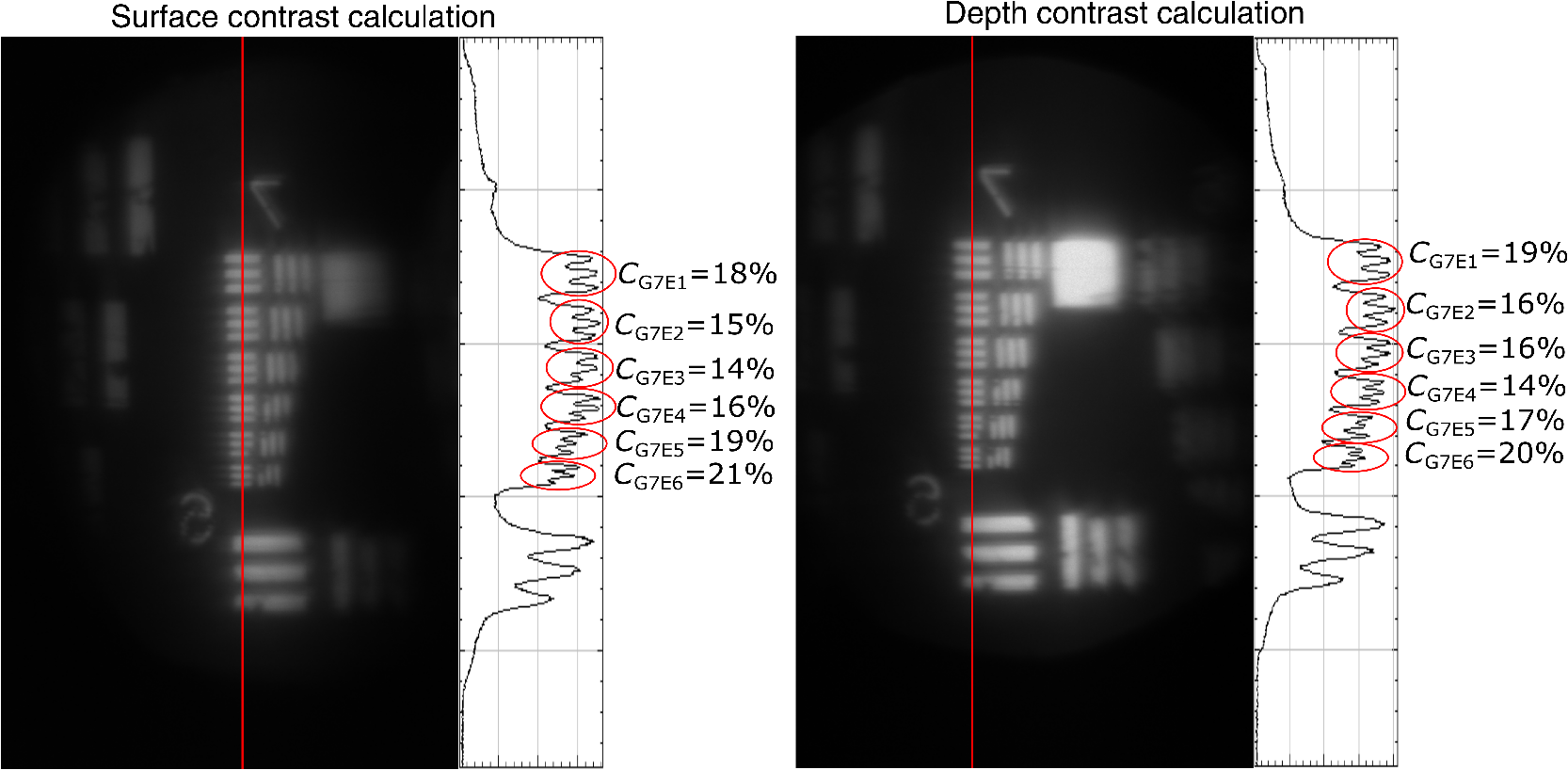 During evaluation of the images, it was noted that the FOV is not a flat plane. The left side of each channel provides a different focus than the right side of each channel. This effect is due to the chromatic focus of the GRIN probe and the wavelength mapping of the holographic element. The FOV width along the -axis (-FOV) gives both spatial and information. The total distance across the FOV in the direction is with a source spectral bandwidth of . The total positive chromatic dispersion that was measured across the FOV in the direction is equivalent to a focal shift of . This shift appears to be a detriment in the case of a perfect planar target; however, when evaluating thick samples, the focal shift does not significantly affect image evaluation. An assessment of tissue image quality is performed using relatively high contrast targets such as onion skin and biopsied human fat. Both samples allow for demonstration of imaging capabilities when scattering effects decrease the reflected light and decrease the contrast values. The images shown in Fig. 9 provide initial imaging capabilities of the endoscopic VHI system using onion skin and human fat samples. The system is designed to have a depth separation of ; for the samples provided, this depth separation is not large enough to see through an entire cell. The cell size of the onion skin is in the range of in length, in width, and in depth.44,45 Fig. 9Ex vivo imaging of organic samples such as (a) onion skin and (b) human fat using the endoscopic VHI.  The human adipose (fat) samples shown have a range of diameters from 50 to .46 The lack of major changes between the surface and depth channels can be attributed to the depth separation being less than the cell thickness. The cell wall contrast values were calculated using a method similar to that of the resolution chart shown in Fig. 8. The results of the contrast measurements for the onion skin and human fat cells, in Fig. 10, show that the background to cell wall signal has contrast values ranging from, 26% to 72%. Although high contrast tissues were able to be visualized using the endoscopic VHI system, low contrast tissue, such as ovary and fallopian tube specimens, provided fewer surface and depth details due to higher scattering and further reduced image contrast. 5.ConclusionsA handheld endoscopic VHI system that is capable of simultaneous multidepth imaging was designed and fabricated. The total probe diameter is 3.8 mm and is capable of being used in a standard surgical trocar and withstands clinical sterilization for in vivo clinical procedures. The spatial resolution was measured at features () using a USAF resolution chart and was designed for imaging the tissue surface and below the surface. The FOV of each imaging channel is , which can be increased if necessary by changing the magnification or utilizing a larger camera aperture. This system operates in reflectance mode without contrast enhancing agents and is capable of imaging high contrast bar targets and organic features such as onion skin and human adipose tissue. Further improvement to the design, such as improved background rejection through wavelength coded methods, wavelength separation across the object field, and modification for operation in fluorescence mode to reduce background signal, are currently being investigated. AcknowledgmentsThis work was supported by a grant from the National Institutes of Health (NIH) (No. R01Ca134424). The group would like to thank Dr. Ken Hatch for his expertise. Isela Howlett received support from the National Science Foundation Bridge to the Doctorate Fellowship, the UA-NASA Space Grant, and the Alfred P. Sloan Foundation (Sloan Foundation, Minority PhD program). The authors would like to acknowledge the help of Lam Optics in Tucson, Arizona, for their assistance with polishing the 0.8-mm-thick window pieces. Last, many thanks to Juan Russo and Tyler Tate for providing additional assistance in the areas of epoxy curing and Gaussian modeling. ReferencesAmerican Cancer Society, “Cancer facts and figures 2016,”
(2016) https://www.cancer.org/research/cancer-facts-statistics/all-cancer-facts-figures/cancer-facts-figures-2016.html March ). 2016). Google Scholar
L. P. Hariri et al.,
“Laparoscopic optical coherence tomography imaging of human ovarian cancer,”
Gynecol. Oncol., 114
(2), 188
–194
(2009). http://dx.doi.org/10.1016/j.ygyno.2009.05.014 GYNOA3 Google Scholar
R. A. Wall and J. K. Barton,
“Fluorescence-based surface magnifying chromoendoscopy and optical coherence tomography endoscope,”
J. Biomed. Opt., 17
(8), 086003
(2012). http://dx.doi.org/10.1117/1.JBO.17.8.086003 JBOPFO 1083-3668 Google Scholar
A. Latrive and A. C. Boccara,
“In vivo and in situ cellular imaging full-field optical coherence tomography with a rigid endoscopic probe,”
Biomed. Opt. Express, 2
(10), 2897
–2904
(2011). http://dx.doi.org/10.1364/BOE.2.002897 BOEICL 2156-7085 Google Scholar
R. Cernat et al.,
“Ex vivo optical coherence tomography imaging of larynx tissues using a forward-viewing resonant fiber-optic scanning endoscope,”
Proc. SPIE, 8213 82133M
(2012). http://dx.doi.org/10.1117/12.911209 PSISDG 0277-786X Google Scholar
A. F. Gmitro, A. R. Rouse and A. Kano,
“In vivo fluorescence confocal microendoscopy,”
in Proc. IEEE Int. Symp. Biomedical Imaging,
277
–280
(2002). http://dx.doi.org/10.1109/ISBI.2002.1029247 Google Scholar
A. A. Tanbakuchi et al.,
“Clinical confocal microlaparoscope for real-time in vivo optical biopsies,”
J. Biomed. Opt., 14
(4), 044030
(2014). http://dx.doi.org/10.1117/1.3207139 JBOPFO 1083-3668 Google Scholar
J. Knittel et al.,
“Endoscope-compatible confocal microscope using a gradient index-lens system,”
Opt. Commun., 188 267
–273
(2001). http://dx.doi.org/10.1016/S0030-4018(00)01164-0 OPCOB8 0030-4018 Google Scholar
R. Liang,
“Chapter 5: fluorescence imaging,”
Optical Design for Biomedical Imaging, 165
–232 2010). Google Scholar
Y. Luo et al.,
“Spectrally resolved multidepth fluorescence imaging,”
J. Biomed. Opt., 16
(9), 096015
(2011). http://dx.doi.org/10.1117/1.3626211 JBOPFO 1083-3668 Google Scholar
C. D. Saunter et al.,
“Micro-endoscope for in vivo widefield high spatial resolution fluorescent imaging,”
Biomed. Opt. express, 3
(6), 1274
–1278
(2012). https://doi.org/10.1364/BOE.3.001274 Google Scholar
R. Grange et al.,
“Imaging with second-harmonic radiation probes in living tissue,”
Biomed. Opt. Express, 2
(9), 2532
–2539
(2011). http://dx.doi.org/10.1364/BOE.2.002532 BOEICL 2156-7085 Google Scholar
J. Liu et al.,
“Single-cell screening and quantification of transcripts in cancer tissues by second-harmonic generation microscopy,”
J. Biomed. Opt., 20
(9), 096016
(2015). http://dx.doi.org/10.1117/1.JBO.20.9.096016 JBOPFO 1083-3668 Google Scholar
P. Campagnola,
“Second harmonic generation imaging microscopy: applications to diseases diagnostics,”
Anal. Chem., 83
(9), 3224
–3231
(2011). http://dx.doi.org/10.1021/ac1032325 ANCHAM 0003-2700 Google Scholar
W. J. Tipping et al.,
“Stimulated Raman scattering microscopy: an emerging tool for drug discovery,”
Chem. Soc. Rev., 45
(8), 2075
–2089
(2016). http://dx.doi.org/10.1039/C5CS00693G CSRVBR 0306-0012 Google Scholar
O. Masihzadeh et al.,
“Coherent anti-stokes Raman scattering (CARS) microscopy: a novel technique for imaging the retina,”
Invest. Ophthalmol. Visual Sci., 54
(5), 3094
–3101
(2013). http://dx.doi.org/10.1167/iovs.13-11642 IOVSDA 0146-0404 Google Scholar
Y. Luo et al.,
“Simulations and experiments of aperiodic and multiplexed gratings in volume holographic imaging systems,”
Opt. Express, 18
(18), 19273
–19285
(2010). http://dx.doi.org/10.1364/OE.18.019273 OPEXFF 1094-4087 Google Scholar
P. J. Gelsinger-Austin et al.,
“Optical design for a spatial-spectral volume holographic imaging system,”
Opt. Eng., 49
(4), 043001
(2010). http://dx.doi.org/10.1117/1.3378025 Google Scholar
W. Liu, D. Psaltis and G. Barbastathis,
“Real-time spectral imaging in three spatial dimensions,”
Opt. Lett., 27
(10), 854
–856
(2002). http://dx.doi.org/10.1364/OL.27.000854 OPLEDP 0146-9592 Google Scholar
W. Liu, G. Barbastathis and D. Psaltis,
“Volume holographic hyperspectral imaging,”
Appl. Opt., 43
(18), 3581
–3599
(2004). http://dx.doi.org/10.1364/AO.43.003581 APOPAI 0003-6935 Google Scholar
Y. Luo et al.,
“Phase-contrast volume holographic imaging system,”
Opt. Lett., 36
(7), 1290
–1292
(2011). http://dx.doi.org/10.1364/OL.36.001290 OPLEDP 0146-9592 Google Scholar
A. Sinha and G. Barbastathis,
“N-ocular volume holographic imaging,”
Appl. Opt., 43
(31), 5784
–5795
(2004). http://dx.doi.org/10.1364/AO.43.005784 APOPAI 0003-6935 Google Scholar
J. M. Castro et al.,
“Confocal rainbow volume holographic imaging,”
Opt. Photonics News, 22
(12), 52
(2011). http://dx.doi.org/10.1364/OPN.22.12.000052 OPPHEL 1047-6938 Google Scholar
Y. Luo et al.,
“Multiplexing volume holographic gratings for a spectral-spatial imaging system,”
Proc. SPIE, 6912 69120A
(2008). http://dx.doi.org/10.1117/12.763926 Google Scholar
G. V. Orsinger et al.,
“Simultaneous multiplane imaging of human ovarian cancer by volume holographic imaging,”
J. Biomed. Opt., 19
(3), 036020
(2014). http://dx.doi.org/10.1117/1.JBO.19.3.036020 JBOPFO 1083-3668 Google Scholar
F. Tresserra et al.,
“Histological features of the contralateral ovary in patients with unilateral ovarian cancer: a case control study,”
Gynecol. Oncol., 71
(3), 437
–441
(1998). http://dx.doi.org/10.1006/gyno.1998.5185 GYNOA3 Google Scholar
Y. Luo et al.,
“Silicon oxide nano-particles doped PQ-PMMA for volume holographic imaging filters,”
Opt. Lett., 35 1269
–1271
(2010). http://dx.doi.org/10.1364/OL.35.001269 OPLEDP 0146-9592 Google Scholar
Y. Luo et al.,
“Optimization of multiplexed holographic gratings in PQ-PMMA for spectral-spatial imaging filters,”
Opt. Lett., 33
(6), 566
–568
(2008). http://dx.doi.org/10.1364/OL.33.000566 OPLEDP 0146-9592 Google Scholar
J. K. Kim et al.,
“Fabrication and operation of GRIN probes for in vivo fluorescence cellular imaging of internal organs in small animals,”
Nat. Protoc., 7
(8), 1456
–1469
(2012). http://dx.doi.org/10.1038/nprot.2012.078 1754-2189 Google Scholar
J. K. Kim and S.-H. Yun,
“GRIN microendoscopes for high resolution in-vivo fluorescence imaging in small animals,”
84211P
(2012). http://dx.doi.org/10.1117/12.970382 Google Scholar
S. Schenkl et al.,
“Applications of rigid and flexible GRIN-endoscopes,”
Proc. SPIE, 6433 64330N
(2007). http://dx.doi.org/10.1117/12.702413 PSISDG 0277-786X Google Scholar
T. Xie et al.,
“GRIN lens rod based probe for endoscopic spectral domain optical coherence tomography with fast dynamic focus tracking,”
Opt. Express, 14
(8), 3238
–3246
(2006). http://dx.doi.org/10.1364/OE.14.003238 OPEXFF 1094-4087 Google Scholar
M. J. Levene et al.,
“In vivo multiphoton microscopy of deep brain tissue,”
J. Neurophysiol., 91
(4), 1908
–1912
(2004). http://dx.doi.org/10.1152/jn.01007.2003 JONEA4 0022-3077 Google Scholar
GoFoton, “SELFOC® Lenses,”
(2013) https://welcome.gofoton.com/passive-optics/selfoc-lenses/ September ). 2013). Google Scholar
Epo-Tek, “Epo-Tek 301 Product Detail,”
(2013) http://www.epotek.com/site/component/products/productdetail.html?cid[0]=231 March ). 2013). Google Scholar
MDDI, “Compatibility of Medical Devices and Materials with Low-Temperature Hydrogen Peroxide Gas Plasma MDDI Medical Device and Diagnostic Industry News Products and Suppliers,”
(2014) http://www.mddionline.com/article/compatibility-medical-devices-and-materials-low-temperature-hydrogen-peroxide-gas-plasma September ). 2014). Google Scholar
R. A. McLaughlin, D. Lorenser, D. D. Sampson,
“Needle probes in optical coherence tomography,”
Handbook of Coherent-Domain Optical Methods, 1066
–1102 2nd ed.Springer, New York
(2013). Google Scholar
H. Kogelnik,
“Coupled wave theory for thick hologram gratings,”
Bell Syst. Tech. J., 48 2909
–2947
(1969). http://dx.doi.org/10.1002/bltj.1969.48.issue-9 BSTJAN 0005-8580 Google Scholar
J. M. Castro et al.,
“Spatial–spectral volume holographic systems: resolution dependence on effective thickness,”
Appl. Opt., 50
(7), 1038
–1046
(2011). http://dx.doi.org/10.1364/AO.50.001038 Google Scholar
J. M. Schmitt, S. H. Xiang and K. M. Yung,
“Speckle in optical coherence tomography,”
J. Biomed. Opt., 4
(1), 95
–105
(1999). http://dx.doi.org/10.1117/1.429925 JBOPFO 1083-3668 Google Scholar
J. M. Schmitt,
“Array detection for speckle reduction in optical coherence microscopy,”
Phys. Med. Biol., 42 1427
–1439
(1997). http://dx.doi.org/10.1088/0031-9155/42/7/015 PHMBA7 0031-9155 Google Scholar
W. Wang and C. Li,
“Measurement of the light absorption and scattering properties of onion skin and flesh at 633 nm,”
Postharvest Biol. Technol., 86 494
–501
(2013). http://dx.doi.org/10.1016/j.postharvbio.2013.07.032 PBTEED Google Scholar
H. Gausman, W. Allen and D. Escobar,
“Refractive index of plant cell walls,”
Appl. Opt., 13
(1), 109
–111
(1974). http://dx.doi.org/10.1364/AO.13.000109 APOPAI 0003-6935 Google Scholar
B. W. Pogue and M. S. Patterson,
“Review of tissue simulating phantoms for optical spectroscopy, imaging and dosimetry,”
J. Biomed. Opt., 11
(4), 041102
(2014). http://dx.doi.org/10.1117/1.2335429 JBOPFO 1083-3668 Google Scholar
BiographyIsela D. Howlett is a graduate research associate at the University of Arizona in Tucson, Arizona, USA. Her academic background includes a BS degree in optical sciences and engineering from the University of Arizona and an MS degree in electrical engineering from Colorado State University. She will be receiving her PhD in optical sciences in August 2017. Wanglei Han is a PhD candidate in optical sciences at the University of Arizona, USA. His research interests include design, fabrication, and optimization of volume holographic imaging systems (VHIS) for biomedical applications. Michael Gordon earned his BS in electrical engineering from the University of California, San Diego, and his MS in optical sciences from the University of Arizona. From 2011 to 2014 he worked as a graduate research assistant for Dr. Raymond Kostuk, researching holographic optical systems with applications in solar energy and medical imaging. He presently works as an R&D Optical Engineer at Alcon in Lake Forest, CA developing ophthalmic surgical products including endoscopes, stereo microscopes, and illumination systems. Photini F. S. Rice holds an associate in applied science in medical technology and has American Society for Clinical Pathology certification. She worked for 13 years as a medical technologist and technical consultant in a clinical laboratory, including achieving Clinical Laboratory Improvement Amendments certification for the laboratory. Currently, she is a senior research specialist at the University of Arizona with 7 years of experience in cardiovascular research and the past 10 years in cancer imaging. Jennifer K. Barton is a professor of biomedical engineering and interim director of the BIO5 Institute at the University of Arizona. Her research focuses on the development of miniature multimodality optical endoscopes for early detection of cancer, including instrumentation design, preclinical experiments, and translation to human pilot clinical studies. Raymond K. Kostuk has a joint professor position with UA’s ECE Department and the College of Optical Sciences. He received a PhD in electrical engineering from Stanford University, in 1986. After completing his PhD, he spent a year at the IBM Research Center. His primary area of expertise is in holographic concepts, materials, and applications. He is a fellow of the Optical Society of America and SPIE. |