
|
|
|
Holographic technique has evolved rapidly in recent years, mainly because of increasing demands in recording three-dimensional (3-D) structures of an object.1,2 Because conventional holography requires a coherent light source to create holograms, and fluorescence is incoherent, application of holography in 3-D imaging of fluorescent objects has been limited. Fresnel incoherent correlation holography (FINCH) has recently been introduced to record 3-D information from incoherent sources.3–8 By employing a spatial light modulator (SLM) that splits an incident object beam into two beams, the FINCH system produces self-interference for each object point and incoherently superimposes them to create a Fresnel hologram. The method has been used to design a fluorescence holographic microscope, FINCHSCOPE,5 which records high-resolution 3-D fluorescence images of biological specimens without the need for scanning. The FINCHSCOPE employs three-step phase-shifting interferometry (PSI) to eliminate the twin image and the bias term that result from each single hologram.9 Consequently, three holograms with different phase-shifting factors are required, the phase modulation on the screen of the SLM must refresh upon each acquisition, and the recording speed is limited. In this study, we developed a two-step PSI-based FINCHSCOPE that requires only two holograms for reconstruction of a microscopic fluorescent object. An electron-multiplying charged-coupled-device (EMCCD) camera, working in frame-transfer mode, was utilized to record the holograms. The two exposures and the frame transfers were controlled by two specific sets of parallel-register clock sequences to match the refresh rate of the SLM (for full digital variable resistor [DVR] settings, 0.03 to 4.19 V, that lead to modulation at 1064-nm wavelength, the rise time is 16 ms and the fall time is 21 ms; for the DVR settings that lead to modulation at 633 nm, 1.48 to 2.87 V, the rise time is 23 ms and the fall time is 54 ms), enabling rapid acquisition () of 3-D microscopic images. Figure 1 is a schematic of our experimental setup, which is similar to the FINCHSCOPE developed by Rosen and Brooker.5 The fluorescent sample is excited by a mercury arc lamp with an excitation filter that selects wavelengths centered at 475 nm for excitation. The objective collects fluorescence centered at 508 nm (Olympus, Tokyo, , 0.30 NA), and it passes through a dichroic mirror and an emission filter. It is then reflected at 12 deg from a phase-only SLM (PLUTO NIR2, pixels) and projected onto an EMCCD (Andor , 14 bit, , ). Fig. 1Schematic of the experimental setup: (a) Phase map loaded on the spatial light modulator (SLM) where half of randomly selected pixels display a constant phase and the remaining pixels display a quadratic phase; (b) fluorescent sample fabricated by curing fluorescent beads in a PDMS membrane. 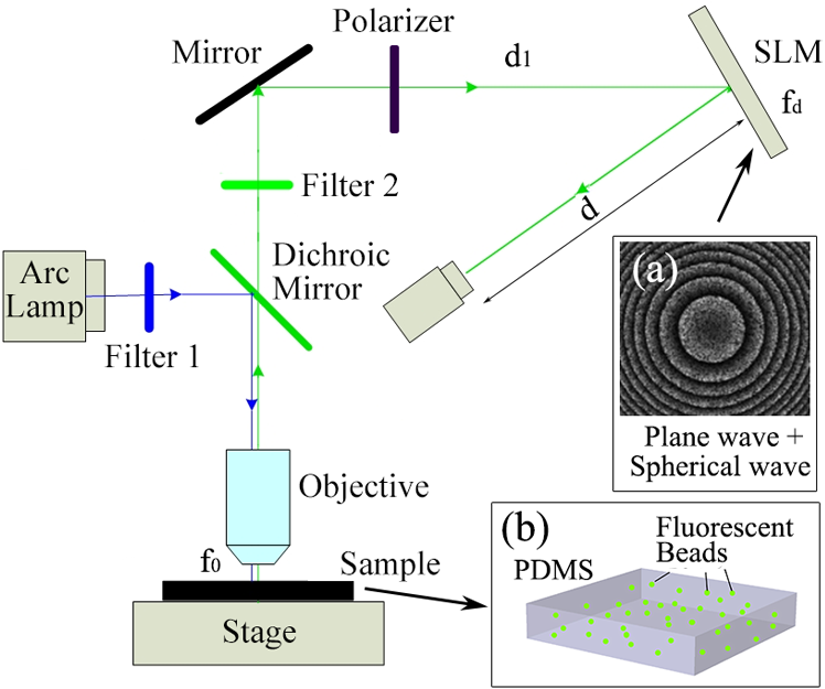 To study the effectiveness of the two-step phase-shifting approach, we fabricated a fluorescent sample, as shown in Fig. 1(b), we added fluorescent polymer microspheres (Duke Scientific Corp., California, 35 to 8, 48-μm diameter, excitation maxima 468 nm, emission maxima 508 nm) to a liquid mixture of a poly-dimethylsiloxane (PDMS) base and a curing agent (ratio 10:1). Once the PDMS mixture was cured, the fluorescent beads were randomly distributed at various depths of the PDMS membrane. The key element of the PSI-based FINCHSCOPE is the SLM. Several strategies for modulating an SLM to produce the FINCH interference have been reported, including the plane wave plus spherical wave method,3 the dual-spherical wave method,7 and the polarization method.8 Our two-step PSI technique is applicable to the FINCHSCOPE with any of these SLM modulation strategies. Here, we use the plane wave plus spherical wave method as an example to describe how we reconstructed a 3-D fluorescent object with only two holograms. As described by Rosen and Brooker,3 mathematically the desired reflection function of the SLM can be expressed as where is a quadratic operator such that )], representing a Fresnel lens with a focal length of relative to a wavelength ; the constant phase term, 1/2, denotes a plane wave modulation; and is the phase-shifting factor. The phase map of the SLM modulation function is shown in Fig. 1(a).To theoretically explain the working process of the two-step phase-shifting FINCHSCOPE, we assume a 3-D fluorescent object located at the working distance, , of the objective lens, as shown in Fig. 1. The hologram recorded by the CCD camera, according to Rosen and Brooker,3 can be written as where is a constant and can be neglected in the reconstruction process, is the sum of the intensities of the two SLM-split beams at the CCD plane, represents the lateral location in the reconstruction coordinates, and is the reconstruction distance related to the object’s depth information. Equation (2) can be broken down into three parts, a bias term and two correlation terms, which carry the virtual and real images of the 3-D object. Here, we achieve the two-step technique by approximately estimating the bias term in the hologram using a two-dimensional (2-D) low-pass filter in the frequency domain.10,11 The low-pass filtering method can be performed with the following three steps:12
In our study, we utilized a Hanning filter to retrieve the low-frequency bias in a hologram. The Hanning filter function is represented as10 where and are non-negative integers and denote the window size of the filter. In our case, the window was set to fit the size of the CCD image plane, pixels. Upon retrieval by the Hanning filter, the bias term can be subtracted from the recorded holograms, and thus we haveFor simplification, we use and to represent the two integral parts in Eq. (4). Then, Eq. (4) can be rewritten as For the proposed two-step PSI-based FINCHSCOPE, two holograms with different phase-shifting factors, and , are required. can be arbitrarily selected, while must be a shifting from , that is . After applying the Hanning filter on both holograms, and , and subtracting the bias components from them, we can then create a Fresnel hologram using the two holograms according to the following equation: where is a neglectable constant, and thus we haveConsequently, a 3-D image of the object can be reconstructed by where the asterisk denotes a 2-D convolution.In our experiment, the two holograms were captured with phase-shifting factors of 0 and , respectively. Two corresponding bias-free holograms were calculated using the described Hanning filter with a window of pixels such that the noise-like bias background was suppressed, and the correlation component was well retained in the holograms (results are not shown here). With the proposed two-step PSI, we reconstructed the image of a 3-D fluorescent sample. The reconstructions are shown in Fig. 2. The first image, Fig. 2(a), is a regular fluorescence image showing the map of the fluorescent beads in 2-D. The other three images were reconstructed with different Fresnel diffraction distances; they display focused views of various fluorescent beads at different depths. In each image, a red arrow points to a specific bead in focus. These results demonstrated the 3-D information acquisition capability of the two-step PSI-based FINCHSCOPE. Fig. 2Two-step phase-shifting reconstruction results: (a) regular fluorescence image under microscope; (b)–(d) reconstructed images with different diffraction distances, . Red arrows indicate locations of different fluorescent beads in focus.  Compared to the original FINCHSCOPE, the two-step phase-shifting method has a faster imaging rate because only two holograms are required. Figure 3(a) is a schematic of the clock sequence that was utilized to synchronize the phase refreshment on the SLM and the CCD exposure. It is possible that our method could double the imaging speed of the FINCHSCOPE. Fig. 3(a) Optimized synchronization of clocks of SLM and CCD; (b) schematic of frame-straddling technique. 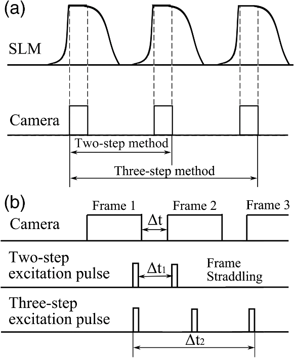 The SLMs with a super-fast refresh rate (500 Hz or above, e.g., boulder nonlinear systems XY Series SLM) are commercially available. Thus, the 3-D imaging speed of the FINCHSCOPE would be limited not by the SLM’s refresh rate but by the camera’s readout time between successive frames. In the case of two-step PSI, it is possible to employ the frame-straddling technique to achieve very short separation time (e.g., submicroseconds) between two consecutive exposures with a frame transfer camera. The working principle of frame-straddling13 is illustrated in Fig. 3(b). The gap between two camera frames is denoted by , and the interval of two excitation pulses by . The double-pulse illuminations occurred at the end of the first frame and the beginning of the second frame, respectively. When an excitation flash lamp and a frame transfer camera are precisely synchronized, the frame-straddling technique enables ; that is, the time separation of recording two holograms could be reduced to hundreds of nanoseconds. Obviously, this technique is not applicable to three successive captures and thus not to three-step PSI. The total time required to record three successive holograms, , is at least equal to a full frame duration plus two interframe gaps, which are typically in milliseconds. As a consequence, two-step PSI could be more than 1000 times faster than three-step PSI. In conclusion, we have developed a two-step phase-shifting FINCHSCOPE that requires only two holograms to reconstruct a 3-D fluorescent sample. The two-step phase-shifting strategy could be applied to other FINCH imaging systems at both the microscales and the macroscales. The strategy could be used in observation of dynamic 3-D processes with incoherent light sources, such as fluorescence. It should also be noted that the two-step PSI method involves digital-signal processing operations, low-pass filtering, and low-frequency subtraction. Although the Hanning filter has been shown to be ideal for two-step PSI, low-pass filters always result in slightly degraded 3-D reconstruction. The two-step phase-shifting method greatly increases imaging speed, but slightly decreases image quality compared with the three-step phase-shifting method. AcknowledgmentsThis work was supported by National Institutes of Health (P20RR021949); National Science Foundation (MRI CBET-0923311); Guangdong Provincial Department of Science and Technology, China (2011B050400011); and the grant established by the State Key Laboratory of Precision Measuring Technology and Instruments (Tianjin University). ReferencesD. Gabor,
“A new microscopic principle,”
Nature, 161 777
(1948). http://dx.doi.org/10.1038/161777a0 NATUAS 0028-0836 Google Scholar
J. Garcia-Sucerquiaet al.,
“Digital in-line holographic microscopy,”
Appl. Opt., 45
(5), 836
–850
(2006). http://dx.doi.org/10.1364/AO.45.000836 APOPAI 0003-6935 Google Scholar
J. RosenG. Brooker,
“Digital spatially incoherent Fresnel holography,”
Opt. Lett., 32
(8), 912
–914
(2007). http://dx.doi.org/10.1364/OL.32.000912 OPLEDP 0146-9592 Google Scholar
J. RosenG. Brooker,
“Fluorescence incoherent color holography,”
Opt. Express, 15
(5), 2244
–2250
(2007). http://dx.doi.org/10.1364/OE.15.002244 OPEXFF 1094-4087 Google Scholar
J. RosenG. Brooker,
“Non-scanning motionless fluorescence three-dimensional holographic microscopy,”
Nat. Photonics, 2 190
–195
(2008). http://dx.doi.org/10.1038/nphoton.2007.300 1749-4885 Google Scholar
J. RosenB. KatzG. Brooker,
“Fresnel incoherent correlation hologram—a review Invited Paper,”
Chin. Opt. Lett., 7 1134
–1141
(2009). http://dx.doi.org/10.3788/COL COLHBT 1671-7694 Google Scholar
B. Katzet al.,
“Enhanced resolution and throughput of Fresnel incoherent correlation holography (FINCH) using dual diffractive lenses on a spatial light modulator (SLM),”
Opt. Express, 20
(8), 9109
–9121
(2012). http://dx.doi.org/10.1364/OE.20.009109 OPEXFF 1094-4087 Google Scholar
G. Brookeret al.,
“Optimal resolution in Fresnel incoherent correlation holographic fluorescence microscopy,”
Opt. Express, 19
(6), 5047
–5062
(2011). http://dx.doi.org/10.1364/OE.19.005047 OPEXFF 1094-4087 Google Scholar
I. YamaguchiT. Zhang,
“Phase-shifting digital holography,”
Opt. Lett., 22
(16), 1268
–1270
(1997). http://dx.doi.org/10.1364/OL.22.001268 OPLEDP 0146-9592 Google Scholar
X. F. Menget al.,
“Wavefront reconstruction by two-step generalized phase-shifting interferometry,”
Opt. Commun., 281
(23), 5701
–5705
(2008). http://dx.doi.org/10.1016/j.optcom.2008.08.010 OPCOB8 0030-4018 Google Scholar
X. F. Menget al.,
“Two-step phase-shifting interferometry and its application in image encryption,”
Opt. Lett., 31
(10), 1414
–1416
(2006). http://dx.doi.org/10.1364/OL.31.001414 OPLEDP 0146-9592 Google Scholar
Digital Image Processing, 2nd ed.Prentice Hall, Upper Saddle River, New Jersey
(2002). Google Scholar
R. J. Adrian, Particle Image Velocimetry, Cambridge Aerospace series, Cambridge University Press, New York
(2011). Google Scholar
|


